
UHF200C - Microphone Auna - Free user manual and instructions
Find the device manual for free UHF200C Auna in PDF.
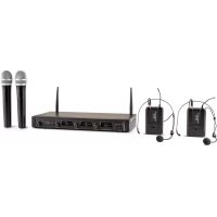
| Product type | UHF wireless microphone system |
| Brand | Auna |
| Model | UHF200C |
| Frequency range | 823 MHz – 832 MHz (UHF) |
| Maximum range | Approx. 50 m (indoor) |
| Modulation type | FM |
| Wave type | PLL |
| Signal-to-noise ratio (receiver) | 90 dB |
| Sensitivity (receiver) | -90 dBm |
| Total harmonic distortion | < 1% |
| Audio frequency range (receiver) | 40 Hz – 17 kHz |
| Audio frequency range (handheld microphone) | 40 Hz – 17 kHz |
| Audio frequency range (bodypack transmitter) | 40 Hz – 16 kHz |
| Microphone type (handheld) | Dynamic, unidirectional |
| Microphone type (bodypack) | Condenser |
| Receiver power supply | 5 V (power adapter) |
| Handheld microphone power supply | 3 V / 3.7 V (Lithium 14500 batteries) |
| Bodypack transmitter power supply | 3 V (batteries) |
| Receiver power consumption | < 300 mA |
| Bodypack transmitter power consumption | < 135 mA |
| Connections | XLR output, 1/4" output, DC 5V input |
| Special features | LCD screen, IR syncing, dual noise reduction, illuminated volume control |
| Intended use | Wireless transmission of speech and singing |
| Maintenance | Clean the exterior with a dry, lint-free cloth. Do not use abrasive products. |
| Safety | Do not use by persons (including children) with reduced capabilities without supervision. Keep out of reach of children. |
Frequently Asked Questions - UHF200C Auna
User questions about UHF200C Auna
0 question about this device. Answer the ones you know or ask your own.
Ask a new question about this device
Download the instructions for your Microphone in PDF format for free! Find your manual UHF200C - Auna and take your electronic device back in hand. On this page are published all the documents necessary for the use of your device. UHF200C by Auna.
USER MANUAL UHF200C Auna
INHALTSVERZEICHNIS
Technische Daten 4
Audioanschluss
natural_image
Two technical illustrations: (a) a medical device with cable and connector, (b) a close-up of a person's ear with a microphone (no text or symbols)natural_image
Two technical illustrations: (a) a medical device with probe and cable, (b) a person wearing a headset (no text or symbols)Member of Berlin Brands Group
Handwerkerstr. 11
15366 Dahlwitz-Hoppegarten
Deutschland
natural_image
Symbol of a trash bin crossed with a diagonal line, representing no waste or discharge (no text or labels)Berlin Brands Group UK Ltd
PO Box 1145
Oxford, OX1 9UW
United Kingdom
Congratulations on purchasing this device. Please read the following instructions carefully and follow them to prevent possible damages. We assume no liability for damage caused by disregard of the instructions and improper use. Scan the QR code to get access to the latest user manual and more product information.

CONTENT
Technical Data 18
Intended Use 19
Device Overview and Function Keys 20
Commissioning and Operation 21
System Connections 23
Receiver Settings 25
Troubleshooting 26
Disposal Considerations 28
Declaration of Conformity 28
TECHNICAL DATA
| Item number 10034468, 100 | 34469, 10034470 |
| Receiver | |
| Oscillation model PLL | |
| Modulation model FM | |
| Frequency deviation ± 75 K | |
| SNR 90 dB | |
| Sensitivity -90 dBm | |
| Frequency response 40 Hz - | 17 kHz |
| Channel interval 300 kHz | |
| T.H.D. < 1% | |
| Output impedance 600 Ohm | |
| Power supply 5 V | |
| Power consumption < 300 mA | |
| Microphone | |
| Power output 10 dBm | |
| Vibration model PLL | |
| Frequency stability ± 0.002% | |
| Max. Modulation degree 75 K | |
| Frequency response 40 Hz - | 17 kHz |
| Type | Dynamic |
| Power supply 3 V / 3.7 V (only apply 14500 Lithium batteries) | |
| Pocket radio transmitter | |
| Power output 10 dBm | |
| Vibration model PLL | |
| Frequency stability ± 0.002% | |
| Frequency response 40 Hz - | 16 kHz |
| Type | Condenser |
| Power supply 3 V | |
| Power consumption < 135 mA | |
INTENDED USE
This device is for the transmission of speech and singing. It is solely designed and may only be used for this purpose. It may only be used in the manner described in this manual.
This appliance is not intended for use by persons (including children) with reduced physical, sensory or mental capabilities, or lack of experience and knowledge, unless they have been given supervision or instruction concerning use of the appliance by a person responsible for their safety.
The microphone system includes microphones with an integrated transmitter, which serve wireless transmission to the receiving unit. The systems operate within the UHF range (823 MHz - 832 MHz). The transmission range is 50 m and depends on the local conditions. The appliance are designed for indoor use only.
DEVICE OVERVIEW AND FUNCTION KEYS
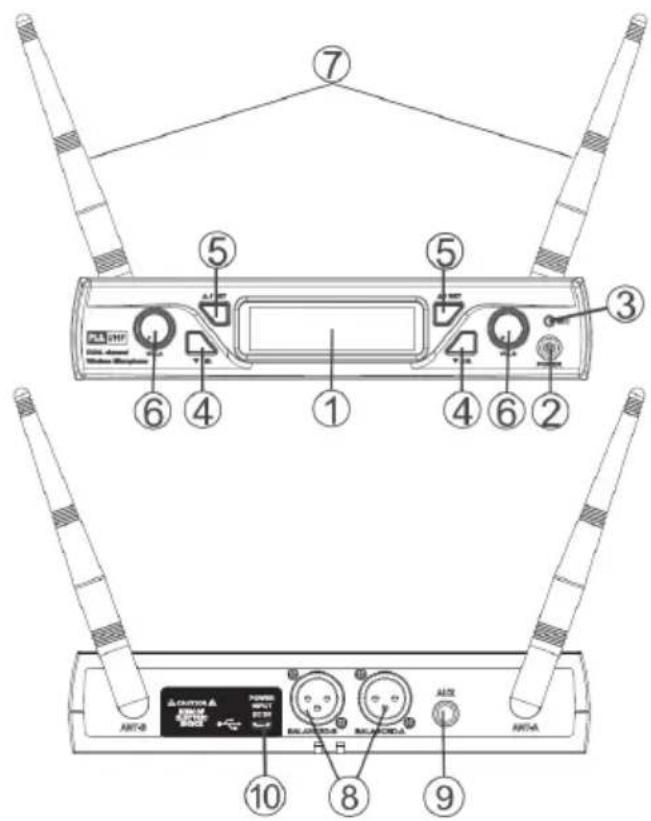
| 1 Screen: Displays information from the receiver and transmitter. | |
| 2 On/Off: Switch receiver on/off | |
| 3 IR Generator: Infrared Signal Generator | |
| 4 Down: Set a channel. Press and hold to activate the IR function. | |
| 5 Up: Set channel | |
| 6 Volume control: Turn to adjust the volume of the receiver output. | |
| 7 Antenna: Signal amplification for the receiver. | |
| 8 | XLR output connector: Connect one end of an XLR audio cable to this connector and plug the other end of the cable into the input of your mixer. |
| 9 | 14 Audio output connector: Connect an audio cable to this connector and the input connector of your amplifier/mixer. |
| 10 | Power connector: Plug one end of the supplied power adapter into this connector and plug the power plug into the wall outlet. |
COMMISSIONING AND OPERATION
Device characteristics
- Multiple channels can be selected for PLL synthesized music playback.
- The UHF frequency range is between 823 MHz - 832 MHz. Frequency interruption will be avoided.
- All available information is displayed on the screen.
- The double noise interruption leads to more efficiency and stability.
- The dynamic and unidirectional cartridge provides clear sound reproduction.
- The unit has been designed to have low consumption at high efficiency.
- The device has self-contained input and output connections, which allow the connection of sound equipment.
- The device has a DC 5V input.
- The device has IR functions to allow operation with a remote control.
• The volume control is illuminated.
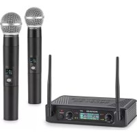
Three different microphone types are available:
- The Tuning Artist UHF is a microphone specially designed for singers, which is held in the hand for wireless performance.
- The Presentation UHF is a microphone specially designed for public speakers, which is invisible, can be attached to clothing, worn and does not need to be held in the hand.
- The Headset-UHF is a headphone mounted microphone specially designed for physically active users who want their hands free.
Microphone functions
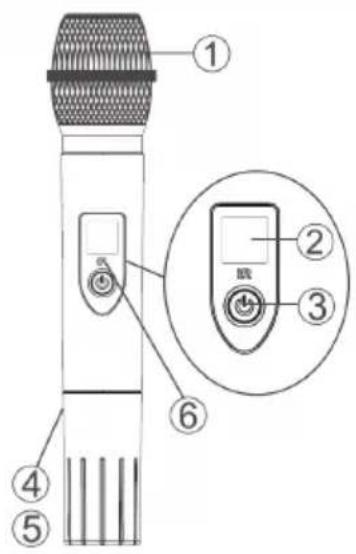
| 1 Grille: Protects the microphone cartridge and reduces wind noise. |
| 2 Information screen: Displays information from the transmitter. |
| 3 On/Off: Turns the transmitter on/off. |
| 4 Batteries: 2 x AA (1.5V) alkaline batteries. |
| 5 Battery cover: Turn clockwise to close and counterclockwise to open. |
| 6 IR: Remote control receiver. |
Pocket radio transmitter functions
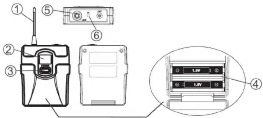
| 1 Antenna: Transmits the RF signal of the transmitter. |
| 2 Information screen: Displays information from the transmitter. |
| 3 On/Off: Turns the transmitter on/off. |
| 4 Battery Cover: Rotate clockwise to close and counterclockwise to open. |
| 5 Input Connector: Connector for clip microphones and headsets. |
| 6 IR: Remote control receiver. |
SYSTEM CONNECTIONS
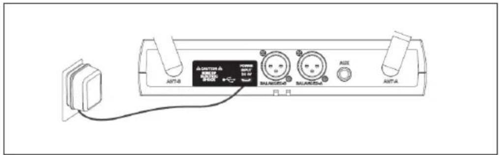
Receiver
Plug the power adapter connector into the DC connector on the back of the receiver. Plug the mains adapter into a 220 V \~ 50 Hz socket.
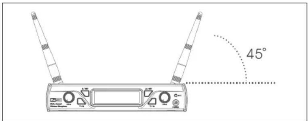
Antenna
Make sure that the antenna angle, seen from the vertical line (see illustration), is 45 degrees.
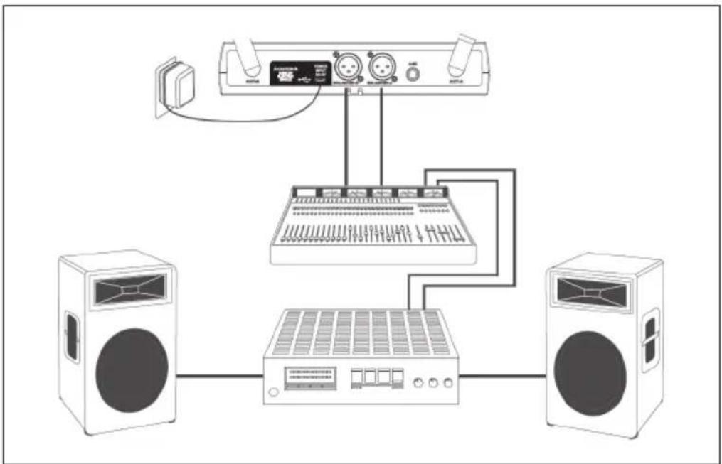
Connect the audio cable to the audio output of the receiver and the input of your amplifier.
flowchart
graph TD
    A["Speaker"] --> B["Audio Device"]
    C["Speaker"] --> D["Audio Device"]
    B --> E["Audio Equipment"]
    D --> E
    E --> F["Speaker"]
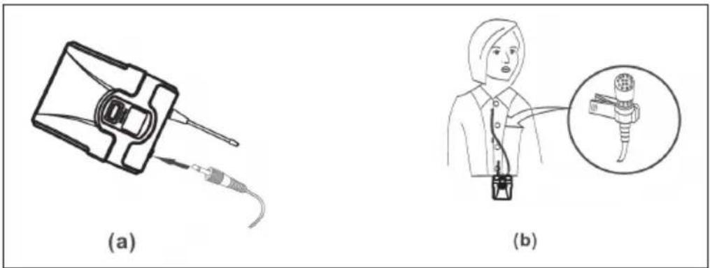
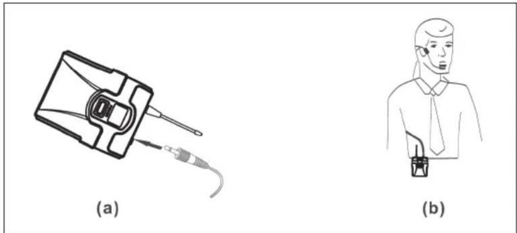
Connecting the lavalier microphone
Connect the connector of the supplied lavalier microphone to the connector of the transmitter (see illustration). Adjust the transmitter to the frequency of the corresponding microphone.
natural_image
Two technical illustrations: (a) a medical device with cable and connector, (b) a close-up of a person's ear with a magnified inset showing the ear structure.Connecting the headset
Connect the connector of the supplied headset to the connector of the transmitter (see figure). Set the transmitter to the frequency of the corresponding microphone.
natural_image
Two technical illustrations: (a) a medical device with probe and cable, (b) a person wearing a headset (no text or symbols)RECEIVER SETTINGS
- Turn on the receiver.
- Channel setting: Press and hold the UP button (5) to enter the channel setting mode. The screen will blink. Then press the UP (5) or DOWN (4) button to select the desired channel.
- Infrared function: Press the DOWN button for a few seconds to activate the IR function. Then move the IR sensor of the transmitter close to the receiver and wait for about 3 seconds (the connection will be successfully established if an RF signal is present).
TROUBLESHOOTING
| Problem Possible cause | Suggested solution | |
| No sound. The screen is | off. Turn on the | transmitter. Make sure that the batteries are inserted correctly, observing the polarity (+/-). The batteries may be empty. Replace them with new batteries. |
| The receiver is off. Make | sure that the AC adapter is properly plugged into a wall outlet. Make sure that the outlet is working and has the correct voltage. | |
| The receiver is turned on and the RF signal indicator is lit. | Increase the volume. Check the connection cables between the receiver and external accessories. | |
| The receiver is on and no RF signal is displayed. | Check that the transmitter and receiver display the same frequency. If not, move the transmitter closer to the receiver. | |
| The output sound is different from the sound setting of the wired device. | The receiver signal indicator A/B lights up. | Adjust the gain level and/or volume of the receiver. |
| Noise is increasing. The | low battery RF signal indicator lights up. | Replace the transmitter batteries. |
| Loud noises or other audible radio signals can be heard. | The A/B signal indicator lights. | Identify potential sources of interference and turn them off or use the microphone system on a different frequency. |
| Transmitter signal loss. | The receiver signal may cancel if the transmitter is too far away from the receiver. The receiver signal indicator A/B will then turn off. | Re-align the receiver and perform a test run. However, if the connection breaks at any point, mark that point as a "dead spot" and avoid it during your performance. |
DISPOSAL CONSIDERATIONS

natural_image
Symbol of a trash bin crossed with a diagonal line, representing no waste or discharge (no text or labels)If there is a legal regulation for the disposal of electrical and electronic devices in your country, this symbol on the product or on the packaging indicates that this product must not be disposed of with household waste. Instead, it must be taken to a collection point for the recycling of electrical and electronic equipment. By disposing of it in accordance with the rules, you are protecting the environment and the health of your fellow human beings from negative consequences. For information about the recycling and disposal of this product, please contact your local authority or your household waste disposal service.
This product contains batteries. If there is a legal regulation for the disposal of batteries in your country, the batteries must not be disposed of with household waste. Find out about local regulations for disposing of batteries. By disposing of them in accordance with the rules, you are protecting the environment and the health of your fellow human beings from negative consequences.
DECLARATION OF CONFORMITY

Manufacturer:
Chal-Tec GmbH, Wallstrasse 16, 10179 Berlin, Germany.
Importer for Great Britain:
Berlin Brands Group UK Ltd
PO Box 1145
Oxford, OX1 9UW
United Kingdom
The complete declaration of conformity of the manufacturer can be found at the following link: https://use.berlin/10034470
Estimado cliente,
ÍNDICE
Datos técnicos 30
Uso previsto 31
natural_image
Two technical illustrations: (a) a medical device with cable and connector, (b) a close-up of a person's ear with a microphone (no text or symbols)natural_image
Two technical illustrations: (a) a medical device with probe and cable, (b) a person wearing a headset (no text or symbols)natural_image
Symbol of a trash bin crossed out by a diagonal line, with no text or labels present.Berlin Brands Group UK Ltd
PO Box 1145
Oxford, OX1 9UW
United Kingdom
SOMMAIRE
Fiche technique 42
Prise audio
natural_image
Two technical illustrations: (a) a medical device with cable and connector, (b) a close-up of a person's medical device with a magnified inset showing internal structure.natural_image
Two technical illustrations: (a) a medical device with probe and cable, (b) a person wearing a headset (no text or symbols)PARAMÈTRES DU RÉCEPTEUR
natural_image
Symbol of a trash bin crossed with a diagonal line, representing no waste or discharge (no text or labels)DÉCLARATION DE CONFORMITÉ

Fabricant :
Chal-Tec GmbH, Wallstraße 16, 10179 Berlin, Allemagne.
Berlin Brands Group UK Ltd
PO Box 1145
Oxford, OX1 9UW
United Kingdom
INDICE
Dati tecnici 54
natural_image
Two technical illustrations: (a) a medical device with cable and connector, (b) a close-up of a person's ear with a microphone (no text or symbols)natural_image
Two technical illustrations: (a) a medical device with probe and cable, (b) a person wearing a headset (no text or symbols)natural_image
Symbol of a trash bin crossed out by a diagonal line, with no text or labels present.CBerlin Brands Group UK Ltd
PO Box 1145
Oxford, OX1 9UW
United Kingdom
natural_image
Abstract white logo design on dark background, resembling stylized letter 'S' or wave form (no text or symbols)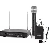

- INHALTSVERZEICHNIS
- Audioanschluss
- Member of Berlin Brands Group
- Dahlwitz-Hoppegarten
- CONTENT
- INTENDED USE
- DEVICE OVERVIEW AND FUNCTION KEYS
- COMMISSIONING AND OPERATION
- Device characteristics
- Microphone functions
- Pocket radio transmitter functions
- SYSTEM CONNECTIONS
- Receiver
- Antenna
- Connecting the lavalier microphone
- Connecting the headset
- RECEIVER SETTINGS
- TROUBLESHOOTING
- DISPOSAL CONSIDERATIONS
- DECLARATION OF CONFORMITY
- Manufacturer:
- Importer for Great Britain:
- Estimado cliente,
- ÍNDICE
- SOMMAIRE
- Prise audio
- PARAMÈTRES DU RÉCEPTEUR
- DÉCLARATION DE CONFORMITÉ
- Fabricant :
- INDICE
Brand : Auna
Model : UHF200C
Category : Microphone