
UHF550 Quartett - Microphone Auna - Free user manual and instructions
Find the device manual for free UHF550 Quartett Auna in PDF.
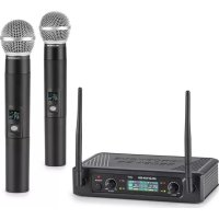
| Product type | UHF wireless microphone system |
| Brand | Auna |
| Model | UHF550 Quartett |
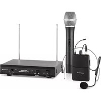
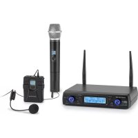
| Number of microphones | 4 (2 handheld microphones, 2 pocket transmitters with lavalier and headset microphones) |
| Receiver power supply | AC adapter 120/230 V AC to 13-15 V DC, 1000 mA |
| Microphone power supply | 2 AA batteries per transmitter |
| Operating frequency | UHF 823-832 MHz (specific frequency on sticker) |
| Maximum range | Approximately 50 meters (depends on local conditions) |
| Receiver connectors | Balanced XLR and 6.35 mm jack outputs |
| Display | LCD screen on receiver and transmitters |
| Antenna | Fixed antenna on receiver, adjustable to 45° |
| Indicators | Power, audio level (AF), RF reception, battery level |
| Settings | Volume, channel selection (up/down buttons) |
| Intended use | Wireless voice transmission (singing, speech) for events, shows, conferences |
| Operating environment | Indoor only |
| Included accessories | AC adapter, audio cables, lavalier microphones, headsets, guitar cable (depending on version) |
| Maintenance | Clean with a dry cloth, avoid moisture and shocks |
| Safety | Do not open, use only with the supplied adapter, observe battery polarity |
| Recycling | Do not dispose of with household waste, take to WEEE collection point |
Frequently Asked Questions - UHF550 Quartett Auna
User questions about UHF550 Quartett Auna
0 question about this device. Answer the ones you know or ask your own.
Ask a new question about this device
Download the instructions for your Microphone in PDF format for free! Find your manual UHF550 Quartett - Auna and take your electronic device back in hand. On this page are published all the documents necessary for the use of your device. UHF550 Quartett by Auna.
USER MANUAL UHF550 Quartett Auna
Member of Berlin Brands Group
Handwerkerstr. 11
15366 Dahlwitz-Hoppegarten
Deutschland
Berlin Brands Group UK Ltd
PO Box 1145
Oxford, OX1 9UW
United Kingdom
https://use.berlin/10010798
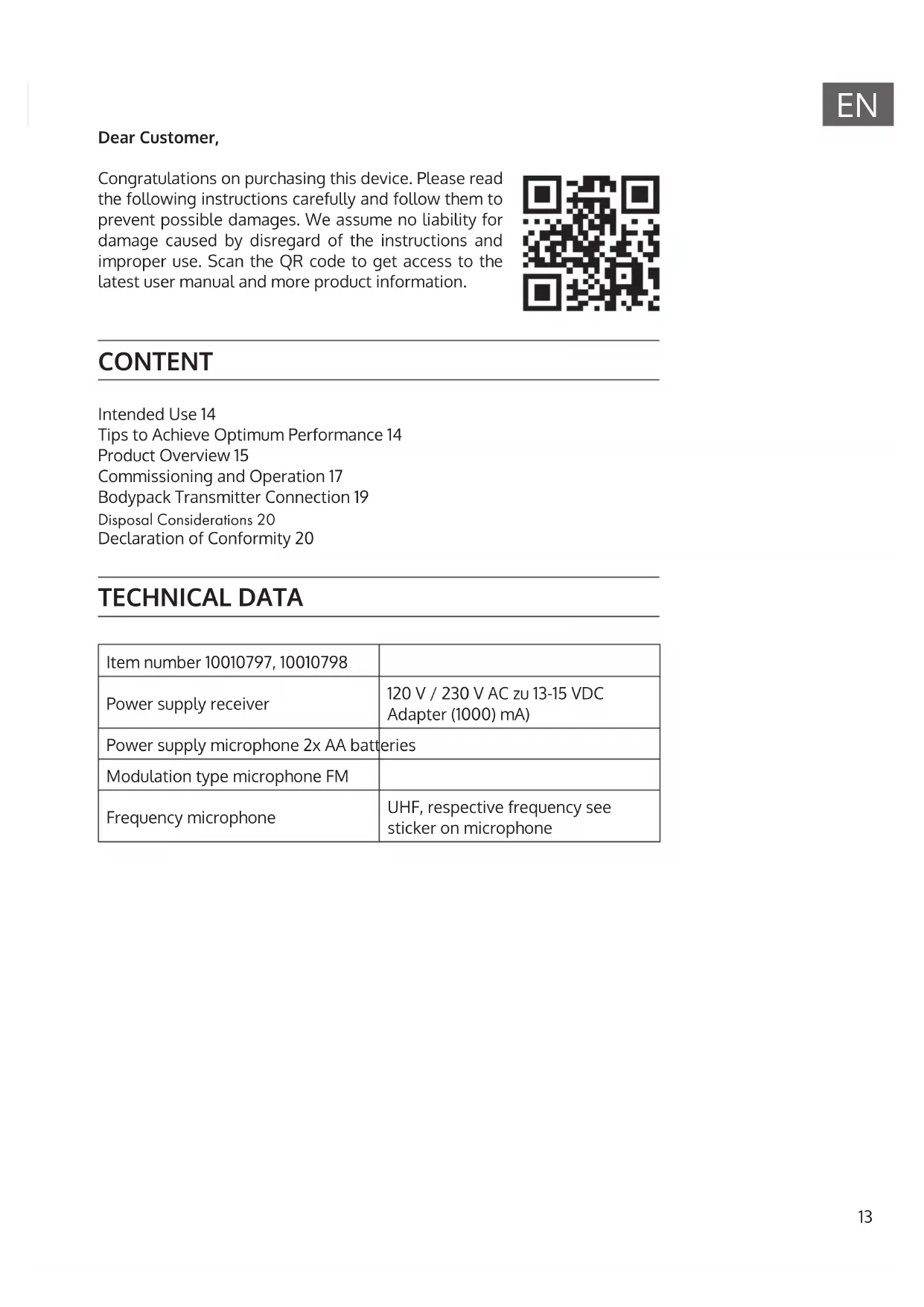
Dear Customer,
Congratulations on purchasing this device. Please read the following instructions carefully and follow them to prevent possible damages. We assume no liability for damage caused by disregard of the instructions and improper use. Scan the QR code to get access to the latest user manual and more product information.

CONTENT
Intended Use 14
Tips to Achieve Optimum Performance 14
Product Overview 15
Commissioning and Operation 17
Bodypack Transmitter Connection 19
Disposal Considerations 20
Declaration of Conformity 20
TECHNICAL DATA
| Item number 10010797, 10010798 | |
| Power supply receiver | 120 V / 230 V AC zu 13-15 VDC Adapter (1000) mA) |
| Power supply microphone 2x AA batteries | |
| Modulation type microphone FM | |
| Frequency microphone | UHF, respective frequency see sticker on microphone |
INTENDED USE
This device is for the transmission of speech and singing. It is solely designed and may only be used for this purpose. It may only be used in the manner described in this manual.
This appliance is not intended for use by persons (including children) with reduced physical, sensory or mental capabilities, or lack of experience and knowledge, unless they have been given supervision or instruction concerning use of the appliance by a person responsible for their safety.
The microphone system includes microphones with an integrated transmitter, which serve wireless transmission to the receiving unit. The systems operate within the UHF range (823 MHz - 832 MHz). The transmission range is 50m and depends on the local conditions. The appliance are designed for indoor use only.
TIPS TO ACHIEVE OPTIMUM PERFORMANCE
- Make sure that you can always see one of the receiving antennas from the transmitting position.
- Keep the distance from the transmitter to the receiver as short as possible.
- Adjust the receiving antennas at a 45^ angle from vertical.
- Make sure that the receiving antenna is not near metal surfaces.
- Look for the battery indicator and replace the batteries when the red light comes on.
- When using the receiver on a rack or equipment system, make sure that the antennas do not touch or cross each other.
- Make a test tour before a demonstration or presentation. If you notice any dead spots, change the location of the receiver. If the dead spots remain, mark and avoid them.
PRODUCT OVERVIEW
| 8 | |
| 1 Power Button: Power ON/OFF the receiver. | |
| 2 Power Indicator: Indicates the power ON/OFF. | |
| 3 LCD Information Display: Show the receiver frequency channel ect. | |
| 4 Down Function Button: Sets channel data. | |
| 5 Up Function Button: Sets channel data. | |
| 6 "AF"Audio Level Indicator: Indicates the wireless system audio signal level. | |
| 7 "RF" signal Indicator: glows when the Receiver receives RF signal from Transmitter. | |
| 8 Antenna | |
| 9 XLR Balanced Output Jack: Connect the audio cable from this jack to the input port of amplifier, mixer. | |
| 10 Volume Knob: Adjust the volume output of the receiver. | |
| 11 1/4" Audio Output Jack: Connect the audio cable from this jack to the input port of amplifier, mixer. | |
| 12 Power Jack: Connect the AC/DC adapter to the receiver. |
Handheld Microphone
| 1 Grille: Protects the cartridge and help reducing the breath sounds and wind noise. |
| 2 LCD information display: Show the receiver fre- quency, channel, etc. |
| 3 Down function button: Sets channel data. |
| 4 UP function button: Sets channel data. |
| 5 Power and Audio Mute Switch. |
| 6 Battery cover: Open it to install the battery. |
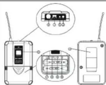
Headset Microphone
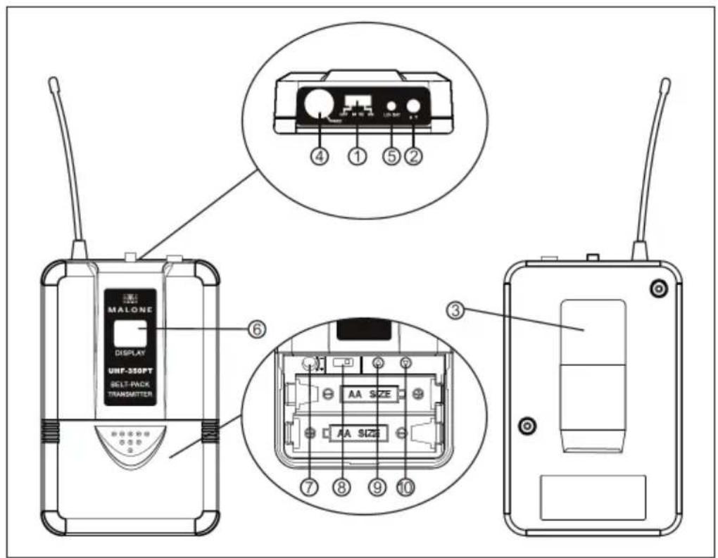
| 1 Power and Audio Mute Switch. |
| 2 Antenna: Transmits the RF signal of transmitter. |
| 3 Belt clip: Attach the transmit-ter to the belt. |
| 4 Audio input jack: it is suitable for lavalier system / headset system. |
| 5 Low battery indicator: Red light glows when it is lack of power and should renew battery. |
| 6 LCD information display: Show the receiver frequency, channel, etc. |
| 7 Gain adjusting volume: Adjust the transmitter audio input gain. |
| 8 State setting switch: Set the using state of lavalier system (L) / headset system (H). |
| 9 UP function button: Sets channel data. |
| 10 Down function button: Sets channel data. |
COMMISSIONING AND OPERATION
Insert the Microphone Batteries

Inserting the batteries into the hand microphone: Slide the battery compartment cover, insert the supplied batteries into the battery compartment, observing the polarity. Close the battery cover.
Inserting the batteries into the hand microphone: Slide the battery compartment cover, insert the supplied batteries into the battery compartment, observing the polarity, and close the battery cover
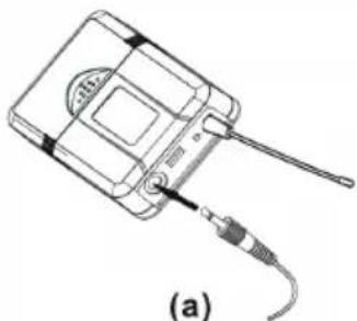
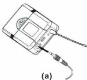
System Connections
| 1 Connect the AC adaptor with the DC power connector on the back of the receiver. Plug the AC adaptor into an AC 120/220 V ~ 50 Hz outlet. |
| 2 Keep the position of antenna at a 45° angle from vertical. |
| 3 Connect the audio cable from the audio output of the receiver to the audio input of an amplifier, a mixer or com- patible devices. |
BODYPACK TRANSMITTER CONNECTION
Lavalier Microphone Connection
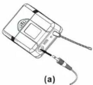
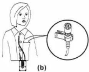
Connect the connector of supplied lavalier microphone to the connecting jack of trans- mitter (see picture). Set the transmitter work state in wireless lavalier system.
Headsat Microphone Connection
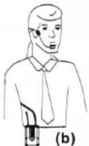
Connect the connector of supplied headset microphone to the connecting jack of trans- mitter (see picture). Set the transmitter work state in wireless headset system.
Guitar Cabla Connection
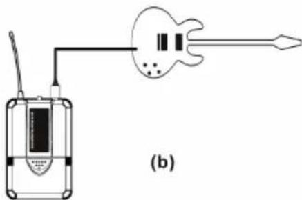
Connect the connector of supplied guitar cable to the connecting jack of transmitter and the other connector to guitar (see picture). Set the transmitter work state in wireless guitar system (G).

If there is a legal regulation for the disposal of electrical and electronic devices in your country, this symbol on the product or on the packaging indicates that this product must not be disposed of with household waste. Instead, it must be taken to a collection point for the recycling of electrical and electronic equipment. By disposing of it in accordance with the rules, you are protecting the environment and the health of your fellow human beings from negative consequences. For information about the recycling and disposal of this product, please contact your local authority or your household waste disposal service.
This product contains batteries. If there is a legal regulation for the disposal of batteries in your country, the batteries must not be disposed of with household waste. Find out about local regulations for disposing of batteries. By disposing of them in accordance with the rules, you are protecting the environment and the health of your fellow human beings from negative consequences.
DECLARATION OF CONFORMITY
CE UK CA
Manufacturer:
Chal-Tec GmbH, Wallstrasse 16, 10179 Berlin, Germany.
Importer for Great Britain:
Berlin Brands Group UK Ltd
PO Box 1145
Oxford, OX1 9UW
United Kingdom
The complete declaration of conformity of the manufacturer can be found at the following link: https://use.berlin/10010798
Estimado cliente:
Berlin Brands Group UK Ltd
PO Box 1145
Oxford, OX1 9UW
United Kingdom
https://use.berlin/10010798
Cher client,
Berlin Brands Group UK Ltd
PO Box 1145
Oxford, OX1 9UW
United Kingdom
CBerlin Brands Group UK Ltd
PO Box 1145
Oxford, OX1 9UW
United Kingdom

- Member of Berlin Brands Group
- Handwerkerstr. 11
- Dahlwitz-Hoppegarten
- Deutschland
- Dear Customer,
- CONTENT
- TECHNICAL DATA
- INTENDED USE
- TIPS TO ACHIEVE OPTIMUM PERFORMANCE
- PRODUCT OVERVIEW
- Handheld Microphone
- Headset Microphone
- COMMISSIONING AND OPERATION
- System Connections
- BODYPACK TRANSMITTER CONNECTION
- Lavalier Microphone Connection
- Headsat Microphone Connection
- Guitar Cabla Connection
- DECLARATION OF CONFORMITY
- Estimado cliente:
- Cher client,
Brand : Auna
Model : UHF550 Quartett
Category : Microphone