TFN11149 - Fan Emerio - Free user manual and instructions
Find the device manual for free TFN11149 Emerio in PDF.



| Product type | Tower fan |
| Brand | Emerio |
| Model | TFN11149 |
| Supply voltage | 220-240 V ~ 50/60 Hz |
| Power consumption | 25 W |
| Maximum air flow | 3.2 m³/min |
| Sound power level | 61 dB(A) |
| Maximum air speed | 1.7 m/s |
| Number of speeds | 3 (S1, S2, S3) |
| Oscillation | Yes |
| Remote control | Yes (AAA batteries not included) |
| Remote control battery type | 2 x AAA |
| Standby power consumption | 0.32 W |
| Service value (SV) | 0.9 (m³/min)/W |
| Use by children | From 8 years with supervision |
| Cleaning | Damp cloth, brush or vacuum cleaner for the grilles |
| Recycling | Compliant with directive 2012/19/EU |
| Included accessories | Remote control, base, screws, manual |
Frequently Asked Questions - TFN11149 Emerio
User questions about TFN11149 Emerio
0 question about this device. Answer the ones you know or ask your own.
Ask a new question about this device
Download the instructions for your Fan in PDF format for free! Find your manual TFN11149 - Emerio and take your electronic device back in hand. On this page are published all the documents necessary for the use of your device. TFN11149 by Emerio.
USER MANUAL TFN11149 Emerio
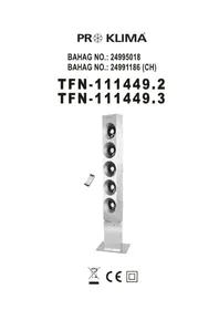
natural_image
Exterior view of a modern vertical speaker tower with five circular fans, mounted on a base (no text or symbols visible)
CE

Inhalt – Obsah – Indhold – Contenido – Contenu – Content – Sadržaj – Tartalom – Innihald – Contenuto – Innehåll – Innhold – Vsebina
Instruction manual – English ...... - 33 -
Upute za rad – Croatian ...... - 39 -
natural_image
Technical line drawing of a mechanical assembly with mounting plate and base (no text or symbols)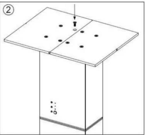
natural_image
Diagram of a simple electrical or mechanical setup with a rectangular base and a vertical panel, showing no text, numbers, or symbols.BATTERIE IN DIE FERNBEDIENUNG EINLEGEN
natural_image
Technical line drawing of a device casing with internal compartments and ports (no text or symbols)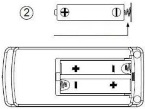
BEDIENUNGSANLEITUNG
flowchart
graph LR
    subgraph S1
        A["●"] --> B["S3"]
        C["○"] --> D["S2"]
        E["○"] --> F["S1"]
    end
    subgraph S2
        G["●"] --> H["S2"]
        I["○"] --> J["S1"]
    end
    subgraph S3
        K["●"] --> L["S2"]
        M["○"] --> N["S1"]
    end
natural_image
Technical line drawing of a mechanical assembly with mounting base and component, no text or symbols present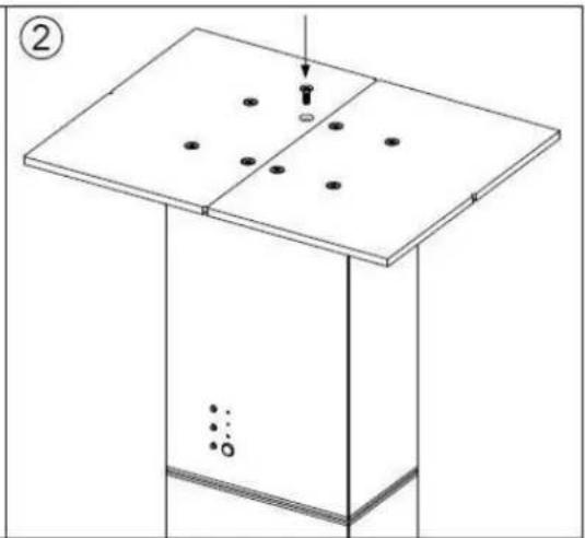
natural_image
Isometric diagram of a rectangular structure with scattered dots on top and a vertical line, no text or symbols presentINSTALACE BATERIÍ V DÁLKOVÉM OVLÁDÁNÍ
natural_image
Technical line drawing of a remote control casing with internal compartments and mounting holes (no text or symbols)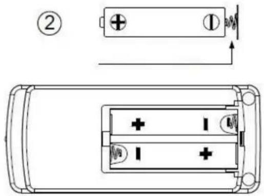
NÁVOD K POUŽITÍ
flowchart
graph LR
    subgraph S1
        A["●"] --> B["S3"]
        C["○"] --> D["S2"]
        E["○"] --> F["S1"]
    end
    subgraph S2
        G["●"] --> H["S2"]
        I["○"] --> J["S1"]
    end
    subgraph S3
        K["●"] --> L["S2"]
        M["○"] --> N["S1"]
    end
natural_image
Technical line drawing of a mechanical assembly with mounting base and component, no text or symbols present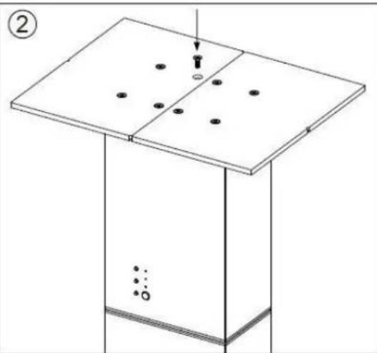
natural_image
Isometric diagram of a mechanical setup with a rectangular base and a vertical plate, showing dots and a downward arrow (no text or symbols)ISÆ TNING AF BATTERIER I FJERNBETJENING
natural_image
Technical line drawing of a remote control casing with internal compartments and mounting holes (no text or symbols)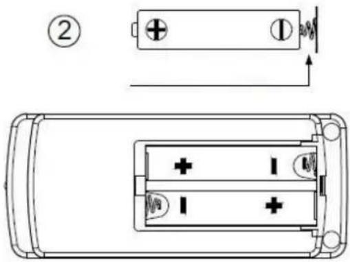
BETJENINGSVEJLEDNING
flowchart
graph LR
    subgraph S1
        A["●"] --> B["S3"]
        C["○"] --> D["S2"]
        E["○"] --> F["S1"]
    end
    subgraph S2
        G["●"] --> H["S2"]
        I["○"] --> J["S1"]
    end
    subgraph S3
        K["●"] --> L["S2"]
        M["○"] --> N["S1"]
    end
natural_image
Technical line drawing of a mechanical assembly with mounting base and component, no visible text or symbols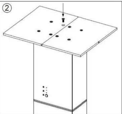
natural_image
Isometric line drawing of a mechanical setup with a flat plate and a vertical rod, showing no text or symbols.INSTALACIÓ N DE LAS PILAS DEL MANDO A DISTANCIA
natural_image
Technical line drawing of a rectangular electronic device casing with internal compartments and ports (no text or symbols)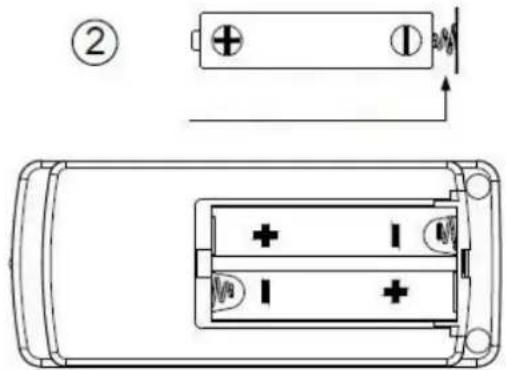
natural_image
Technical line drawing of a mechanical assembly with mounting base and component, no text or symbols present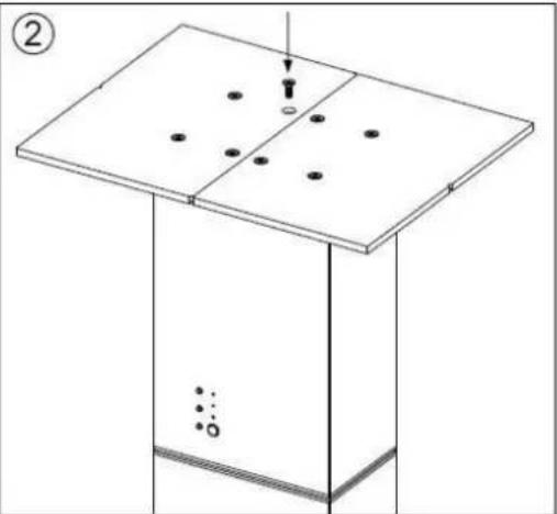
natural_image
Isometric diagram of a rectangular structure with scattered dots and a downward arrow, no text or symbols presentINSTALLATION DES PILES DE LA TÉLÉCOMMANDE
natural_image
Technical line drawing of a remote control casing with internal compartments and mounting holes (no text or symbols)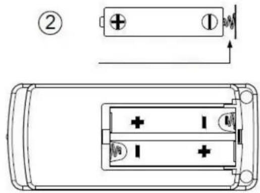
INSTRUCTIONS DE FONCTIONNEMENT
Please read these Operating Instructions through carefully before connecting your appliance to the mains, in order to avoid damage due to incorrect use. Please pay particular attention to the safety information. If you pass the appliance on to a third party, these Operating Instructions must also be handed over.
WARNING – When using electrical appliance, basic safety precautions should always be followed to reduce the risk of fire, electrical shock and personal injury.
SAFETY INFORMATION
-
This appliance can be used by children aged from 8 years and above and persons with reduced physical, sensory or mental capabilities or lack of experience and knowledge if they have been given supervision or instruction concerning use of the appliance in a safe way and understand the hazards involved.
-
Children shall not play with the appliance.
-
Cleaning and user maintenance shall not be made by children without supervision.
-
Incorrect operation and improper handling can lead to faults on the appliance and injuries to the user.
-
In the event of improper use or incorrect handling, no liability can be accepted for any damage that may occur.
-
Do not immerse the unit or mains plug in water or other liquids. There is danger to life due to electric shock! However, if this occurs, remove the mains plug immediately and then have the unit checked by an expert before using it again.
-
Do not operate the appliance if the mains cable or the mains plug show signs of damage, if the appliance has
fallen on the floor or has been otherwise damaged. In such cases take the appliance to a specialist for checking and repair if necessary.
- Never remove the mains plug from the socket by pulling on the mains cable, or with wet hands.
- Ensure that the mains cable does not hang over sharp edges or allow it to become trapped.
- Keep the appliance away from damp, and protect from splashes.
- Keep the appliance away from hot objects (e.g. hotplates) and open flames.
- Keep the appliance and its cord out of reach of children less than 8 years.
- Use the appliance on a flat, dry and heat resistance surface.
- Never leave the appliance in unattended during use.
- Do not store or operate the appliance in the open air.
- Never put fingers or any other objects through the grilles (fan guards) when the fan is running.
- Never operate the appliance without the grilles (fan guards) in place, as serious personal injury may result.
- The appliance must be assembled completely before use.
- Watch out for long hair! It can be caught in the fan owing to the air turbulence.
- Do not point the air flow to the people for a long time.
PARTS DESCRIPTION
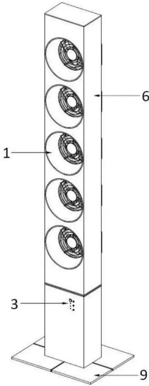
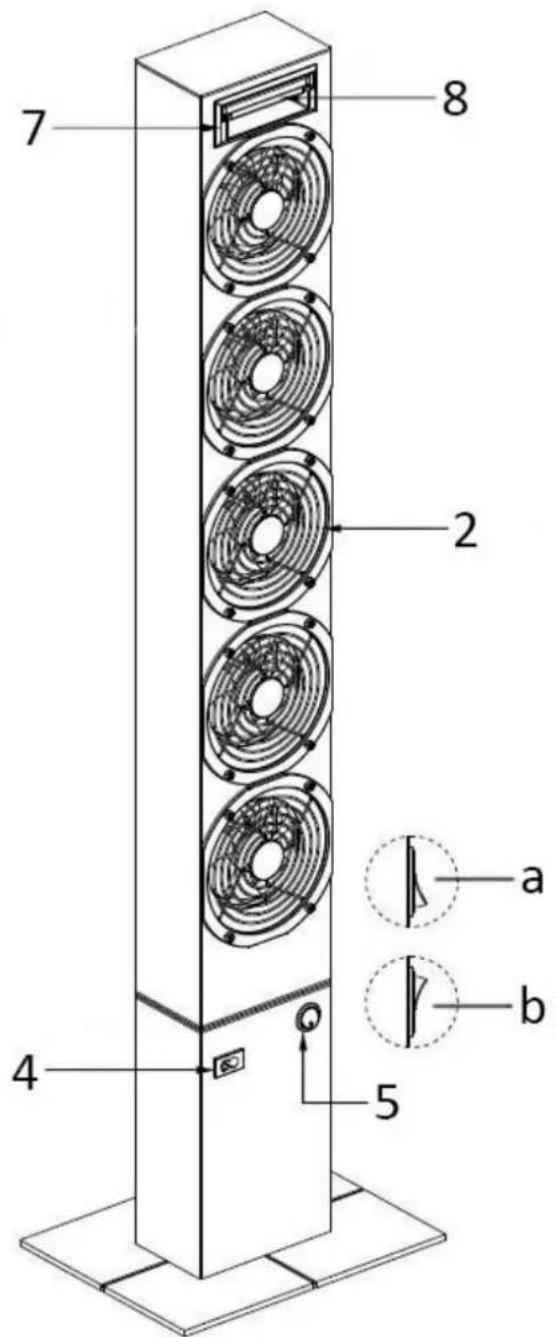
- Wind outlet
- Wind inlet
- Control panel
- Power cord socket
-
Power switch
-
Oscillation part
- Handle
- Remote control
- Base
Note:
The power switch has two states: a = OFF, b = ON. When the power switch is turned on, the indicator light on the switch will illuminate.
REMOTE CONTROL AND CONTROL PANEL ILLUSTRATION
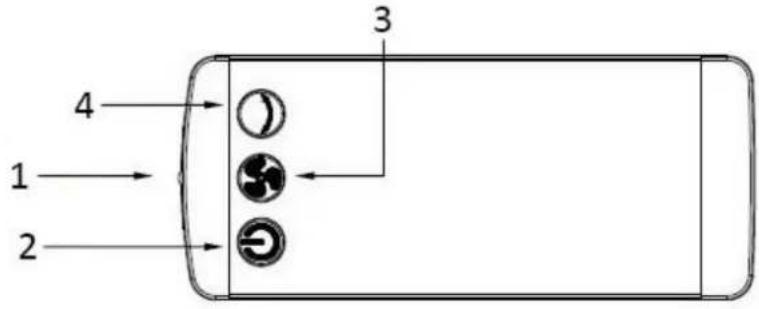
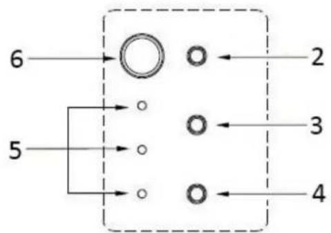
flowchart
graph TD
    A["6"] --> B(( ))
    C["5"] --> D[" "]
    E["2"] --> F[" "]
    G["3"] --> H[" "]
    I["4"] --> J[" "]
- Control sensor
- ON/OFF button
-
Speed selection button
-
Oscillation button
- Speed indicator light
- Signal receiver
BASE ASSEMBLY
① Put the appliance upside down. Place half of the base onto the bottom. Align the four holes and fix the half of base with four screws.
② Place the other half of base besides the fixed half. Align the holes and use the other four screws to fix this half of base.

natural_image
Technical line drawing of a mechanical assembly with mounting bracket and base plate (no text or symbols)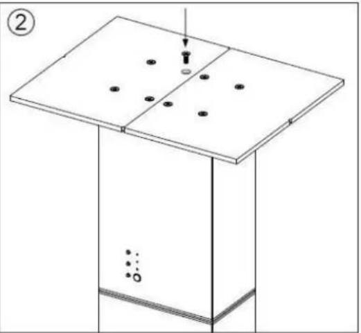
natural_image
Isometric diagram of a rectangular container with a lid and six circular holes, no text or symbols presentREMOTE CONTROL BATTERY INSTALLATION
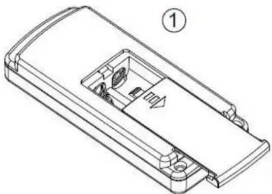
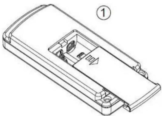
① Press and pull off the back cover on the remote control.
② Put two AAA batteries into the battery compartment. Pay attention to the polarities.
Note! If it is not in use for a long time, please take the batteries out of the remote control.
natural_image
Technical line drawing of a device casing with internal compartments and mounting holes (no text or symbols)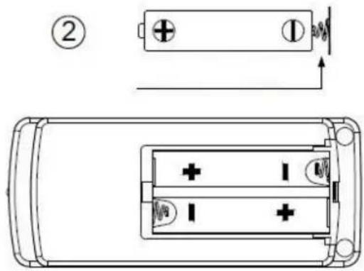
OPERATION INSTRUCTIONS
- Make sure the recharge switch is at "OFF" position before connecting the appliance to a power supply.
-
Insert the power cord into the socket on the back of the appliance, and then plug the power cord into an appropriate power outlet.
-
Press the power switch to the "ON" position. Turn on the appliance by pressing the ON/OFF button.
-
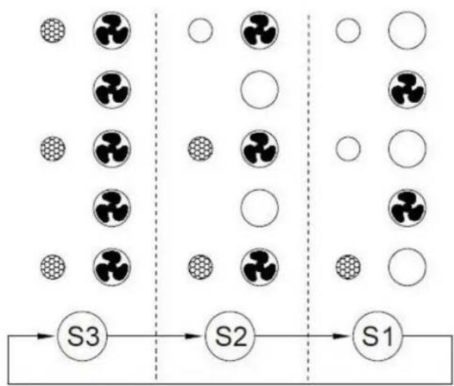
Use the speed selection button to choose the wind type. The default after turning on the appliance is all five little fans running and all three indicator lights illuminating (S3). Press the speed selection button one time, there will be three little fans running and two indicator lights illuminating (S2). Another press to the speed selection button will make only two little fans running and one indicator light illuminating (S1). At this time, if you press the button again, the wind type will turn back to the default setting. (See the illustration below.)
flowchart
graph LR
    subgraph S1
        A["●"] --> B["S3"]
        C["○"] --> D["S2"]
        E["○"] --> F["S1"]
    end
    subgraph S2
        G["●"] --> H["S2"]
        I["○"] --> J["S1"]
    end
    subgraph S3
        K["●"] --> L["S2"]
        M["○"] --> N["S1"]
    end
-
Oscillation: Press the oscillation button to make the upper body of the appliance oscillate or not. The direction of air flow can be adjusted by this way.
-
Turn off the appliance by ON/OFF button when you do not want to use it.
Note:
The buttons on control panel and remote control have the same functions regarding setting the appliance.
CLEANING
- Before servicing the appliance and after each occasion of use, switch off the appliance and unplug the power cord from power outlet if the power cord is connected.
- Never immerse the appliance in water (danger of short-circuit). To clean the appliance, only wipe it down with a damp cloth and then dry it carefully. Always take out the mains plug first.
- Take care that excessive dust does not build up in the air-intake and air-outlet grille, and clean it occasionally using a dry brush or vacuum cleaner.
TECHNICAL DATA
Operating voltage: 220-240V \~ 50/60Hz
Power consumption: 25W
| Eco design requirements | |
| Product information requirements | |
| Maximum fan flow rate (F) | 3,2 m^3/min |
| Fan power input (P) | 3,8 W |
| Service value (SV) | 0,9 ( m^3/min )/W |
| Measurement standard for service value | EN 50564:2011IEC 60879:1986 +cor1:1992EN 60704-2-7:1998 |
| Standby power consumption (PSB) | 0,32 W |
| Fan sound power level (LWA) | 61 dB(A) |
| Maximum air velocity (c) | 1,7 meters/sec |
| Contact details for obtaining more information | BAHAG AGGutenbergstr. 2168167 MannheimGermany |

Recycling – European Directive 2012/19/EU
This marking indicates that this product should not be disposed with other household wastes. To prevent possible harm to the environment or human health from uncontrolled waste disposal, recycle it responsibly to promote the sustainable reuse of material resources. To return your used device, please use the return and collection systems or contact the retailer where the product was
purchased. They can take this product for environmental safe recycling.
UPUTE ZA UPOTREBU
natural_image
Technical line drawing of a mechanical assembly with mounting base and component, no visible text or symbols
natural_image
Diagram of a mechanical setup with a rectangular base and a vertical rod inserted into a plate, showing no text or symbols.ULAGANJE BATERIJA U DALJINSKI UPRAVLJAČ
① Pritisnite i povucite stražnji poklopac na daljinskom upravljaču.
② U pretinac za baterije stavite dvije baterije tipa AAA. Obratite pozornost na polaritet.
Napomena! Izvadite baterije ako daljinski upravljač ne koristite duže vrijeme.
natural_image
Technical line drawing of a remote control casing with internal compartments and mounting holes (no text or symbols)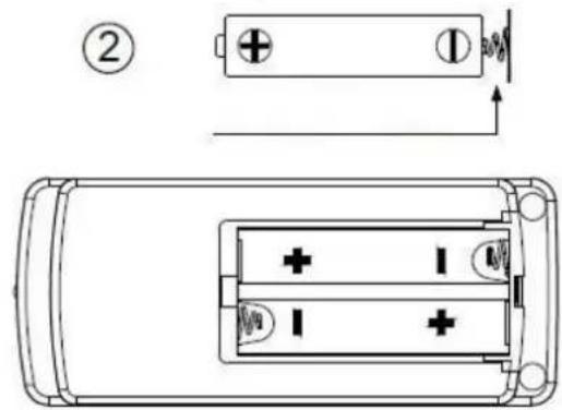
UPUTE ZA RUKOVANJE
flowchart
graph LR
    subgraph S1
        A["●"] --> B["S3"]
        C["○"] --> D["S2"]
        E["○"] --> F["S1"]
    end
    subgraph S2
        G["●"] --> H["S2"]
        I["○"] --> J["S1"]
    end
    subgraph S3
        K["●"] --> L["S2"]
        M["○"] --> N["S1"]
    end
natural_image
Technical line drawing of a mechanical assembly with mounting base and component, no visible text or symbols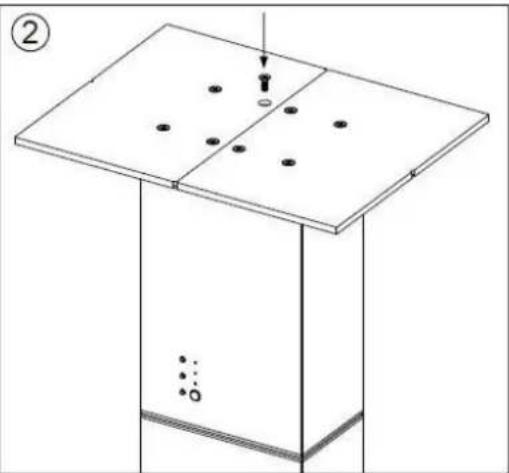
natural_image
Isometric diagram of a table with a tray and a vertical rod, showing no text or symbolsnatural_image
Technical line drawing of a remote control casing with internal compartments and mounting holes (no text or symbols)
KEZELÉSI UTASÍTÁS
natural_image
Technical line drawing of a mechanical assembly with a base plate and mounting bracket (no text or symbols)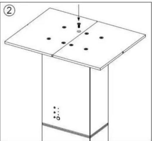
natural_image
Isometric diagram of a rectangular container with a central plate and four circular holes, no text or symbols presentRAFHLÖ D UM KOMID FYRIR I FJARSTÍRINGU
natural_image
Technical line drawing of a remote control casing with internal compartments and mounting holes (no text or symbols)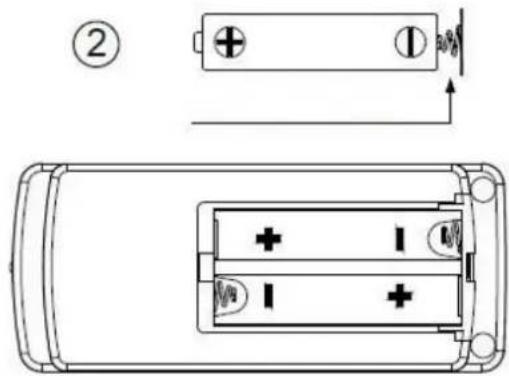
NOTKUNARLEID BEININGAR
natural_image
Technical line drawing of a mechanical assembly with mounting base and component, no text or symbols present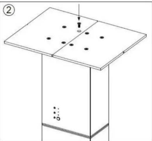
natural_image
Diagram of a simple electrical or mechanical setup with a panel and base, showing no text, numbers, or symbols.natural_image
Technical line drawing of a remote control casing with internal compartments and mounting holes (no text or symbols)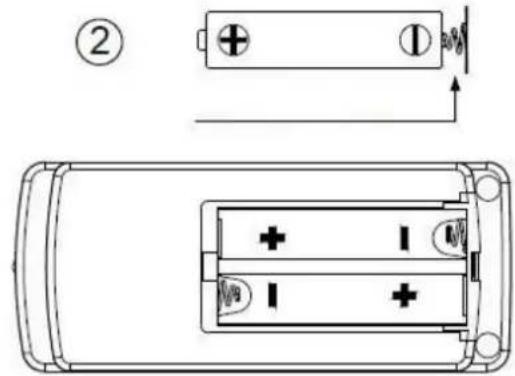
ISTRUZIONI PER L'USO
natural_image
Technical line drawing of a mechanical device with mounting base and internal components (no text or symbols)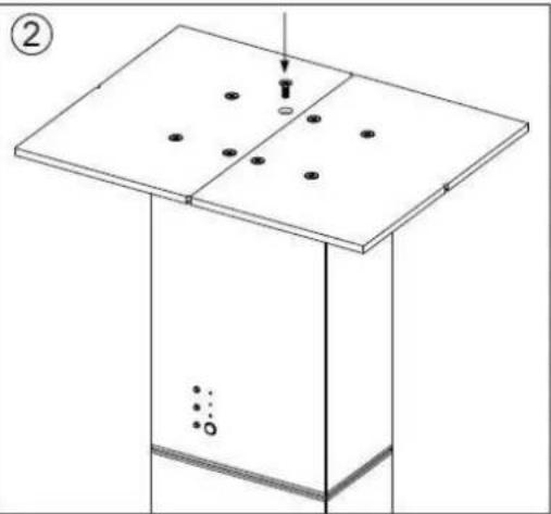
natural_image
Isometric diagram of a rectangular container with a lid and internal holes, no text or symbols presentMONTERA BATTERIER I FJÄRRKONTROLLEN
natural_image
Technical line drawing of a remote control casing with internal compartments and mounting holes (no text or symbols)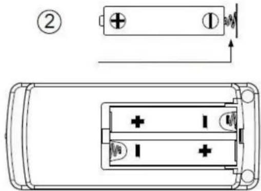
ANVÄNDNINGSINSTRUKTIONER
flowchart
graph LR
    subgraph S1
        A["●"] --> B["S3"]
        C["○"] --> D["S2"]
        E["○"] --> F["S1"]
    end
    subgraph S2
        G["●"] --> H["S2"]
        I["○"] --> J["S1"]
    end
    subgraph S3
        K["●"] --> L["S2"]
        M["○"] --> N["S1"]
    end
natural_image
Technical line drawing of a mechanical assembly with mounting bracket and base plate (no text or symbols)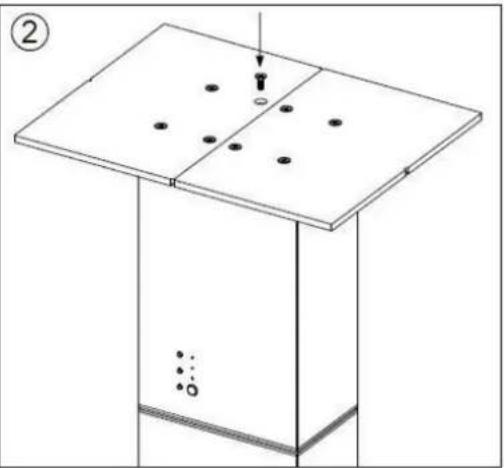
natural_image
Isometric diagram of a rectangular structure with a central plate and four circular holes, no text or symbols present.SETTE INN BATTERIER I FJERNKONTROLLEN
natural_image
Technical line drawing of a remote control casing with internal compartments and mounting points (no text or symbols)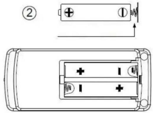
BRUKSANVISNING
flowchart
graph LR
    subgraph S1
        A["●"] --> B["S3"]
        C["○"] --> D["S2"]
        E["○"] --> F["S1"]
    end
    subgraph S2
        G["●"] --> H["S2"]
        I["○"] --> J["S1"]
    end
    subgraph S3
        K["●"] --> L["S2"]
        M["○"] --> N["S1"]
    end
natural_image
Technical line drawing of a mechanical assembly with mounting bracket and base plate (no text or symbols)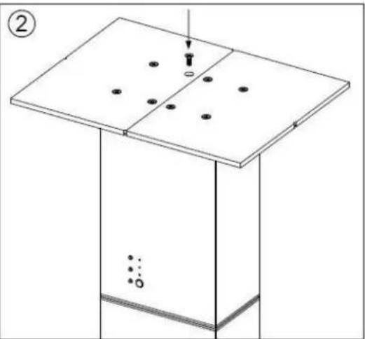
natural_image
Isometric diagram of a rectangular structure with a central plate and scattered dots, no text or symbols presentNAMESTITEV BATERIJE DALJINSKEGA UPRAVLJALNIKA
natural_image
Technical line drawing of a remote control casing with internal compartments and mounting points (no text or symbols)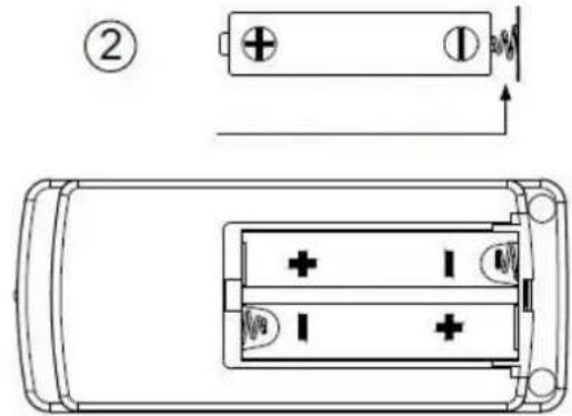
NAVODILA ZA UPRAVLJANJE

- BATTERIE IN DIE FERNBEDIENUNG EINLEGEN
- BEDIENUNGSANLEITUNG
- INSTALACE BATERIÍ V DÁLKOVÉM OVLÁDÁNÍ
- NÁVOD K POUŽITÍ
- ISÆ TNING AF BATTERIER I FJERNBETJENING
- BETJENINGSVEJLEDNING
- INSTALACIÓ N DE LAS PILAS DEL MANDO A DISTANCIA
- INSTALLATION DES PILES DE LA TÉLÉCOMMANDE
- INSTRUCTIONS DE FONCTIONNEMENT
- SAFETY INFORMATION
- Note:
- REMOTE CONTROL AND CONTROL PANEL ILLUSTRATION
- BASE ASSEMBLY
- REMOTE CONTROL BATTERY INSTALLATION
- OPERATION INSTRUCTIONS
- CLEANING
- TECHNICAL DATA
- UPUTE ZA UPOTREBU
- ULAGANJE BATERIJA U DALJINSKI UPRAVLJAČ
- UPUTE ZA RUKOVANJE
- KEZELÉSI UTASÍTÁS
- RAFHLÖ D UM KOMID FYRIR I FJARSTÍRINGU
- NOTKUNARLEID BEININGAR
- ISTRUZIONI PER L'USO
- MONTERA BATTERIER I FJÄRRKONTROLLEN
- ANVÄNDNINGSINSTRUKTIONER
- SETTE INN BATTERIER I FJERNKONTROLLEN
- BRUKSANVISNING
- NAMESTITEV BATERIJE DALJINSKEGA UPRAVLJALNIKA
- NAVODILA ZA UPRAVLJANJE
Brand : Emerio
Model : TFN11149
Category : Fan