SOC222 - Soundbar SAMSUNG - Free user manual and instructions
Find the device manual for free SOC222 SAMSUNG in PDF.
Download the instructions for your Soundbar in PDF format for free! Find your manual SOC222 - SAMSUNG and take your electronic device back in hand. On this page are published all the documents necessary for the use of your device. SOC222 by SAMSUNG.
USER MANUAL SOC222 SAMSUNG
Important Safety Instructions E E
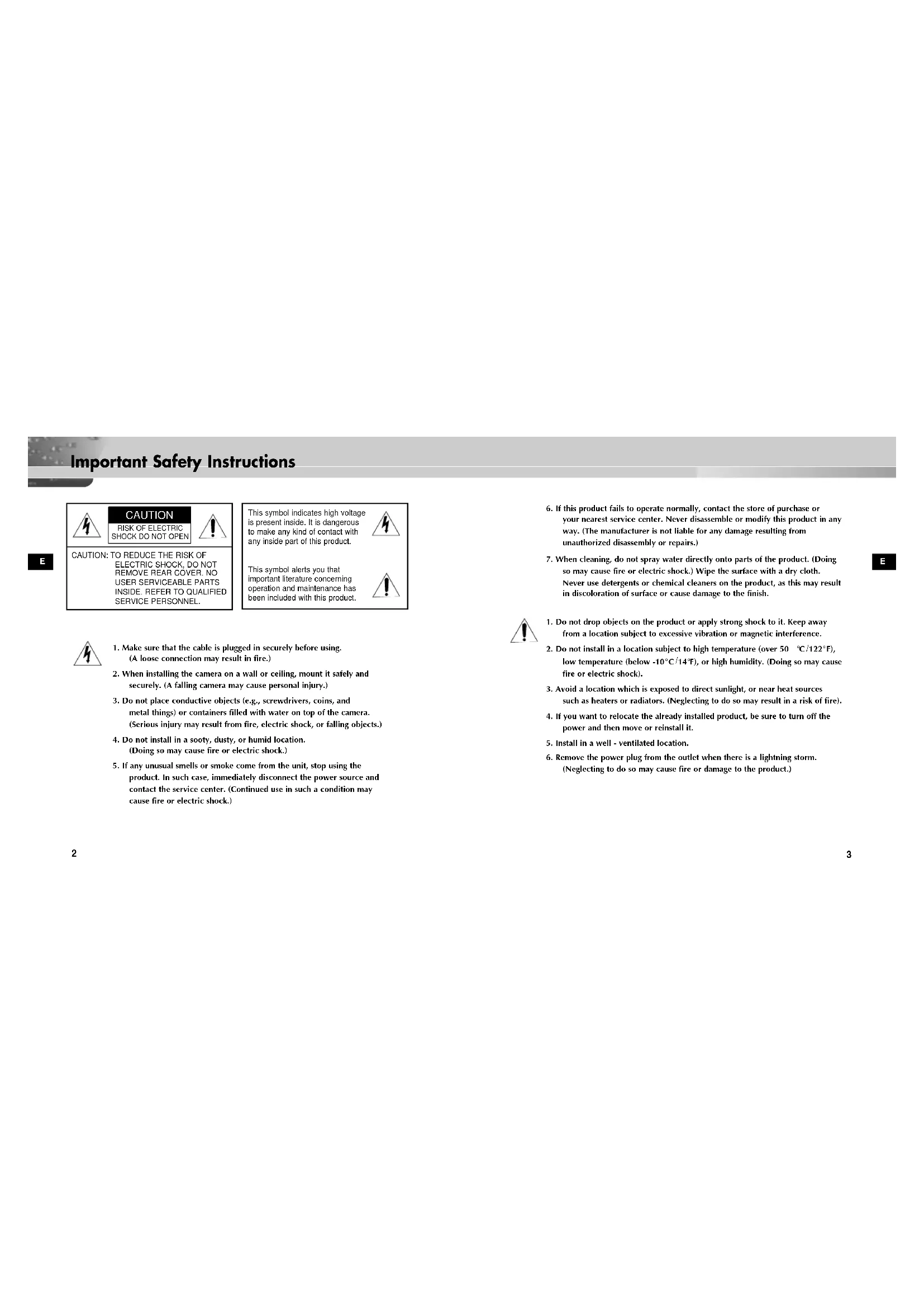
6. If this product fails to operate normally, contact the store of purchase or
your nearest service center. Never disassemble or modify this product in any way. (The manufacturer is not liable for any damage resulting from unauthorized disassembly or repairs.)
7. When cleaning, do not spray water directly onto parts of the product. (Doing
so may cause fire or electric shock.) Wipe the surface with a dry cloth. Never use detergents or chemical cleaners on the product, as this may result in discoloration of surface or cause damage to the finish.
1. Do not drop objects on the product or apply strong shock to it. Keep away
from a location subject to excessive vibration or magnetic interference.
2. Do not install in a location subject to high temperature (over 50
F), or high humidity. (Doing so may cause fire or electric shock).
3. Avoid a location which is exposed to direct sunlight, or near heat sources
such as heaters or radiators. (Neglecting to do so may result in a risk of fire).
4. If you want to relocate the already installed product, be sure to turn off the
power and then move or reinstall it.
5. Install in a well - ventilated location.
6. Remove the power plug from the outlet when there is a lightning storm.
(Neglecting to do so may cause fire or damage to the product.) CAUTION: TO REDUCE THE RISK OFELECTRIC SHOCK, DO NOTREMOVE REAR COVER. NOUSER SERVICEABLE PARTSINSIDE. REFER TO QUALIFIEDSERVICE PERSONNEL.
1. Make sure that the cable is plugged in securely before using.
(A loose connection may result in fire.)
2. When installing the camera on a wall or ceiling, mount it safely and
securely. (A falling camera may cause personal injury.)
3. Do not place conductive objects (e.g., screwdrivers, coins, and
metal things) or containers filled with water on top of the camera. (Serious injury may result from fire, electric shock, or falling objects.)
4. Do not install in a sooty, dusty, or humid location.
(Doing so may cause fire or electric shock.)
5. If any unusual smells or smoke come from the unit, stop using the
product. In such case, immediately disconnect the power source and contact the service center. (Continued use in such a condition may cause fire or electric shock.) This symbol indicates high voltageis present inside. It is dangerousto make any kind of contact withany inside part of this product.This symbol alerts you thatimportant literature concerningoperation and maintenance hasbeen included with this product. CAUTION RISK OF ELECTRIC SHOCK DO NOT OPEN AB68-00431A SOC-222(P)-GB 2003.11.26 9:47 AM Page 24
Table of Contents E E
Chapter 1 About SOC-222(P) 5
Chapter 2 Before Installation 6
Installing SOC-222(P) 8 Appendix SOC-222(P) Pin Configuration 13 SOC-222(P) Specification 14 About SOC-222(P) The SOC-222(P) is a camera for SMO-210T(P) only. It contains a mike inside and will be installed easily by a general user. Meanwhile, the SOC-222(P) is shaped like a infrared ray sensor to reduce the hatred for the conventional camera and it is featured to have the AUTO WHITE BALANCE function and a mike. AB68-00431A SOC-222(P)-GB 2003.11.26 9:47 AM Page 4E
Checking Contents Be sure to check the package contains all the items in it, camera, bracket, accessory box, and cable when unpacked.
Before Installation ✔ Check if the place is hard enough to endure 5 times the total weight (1kg or so) of Camera before installation. ✔ Don’t let the cable get stuck in a wrong place nor let the insulating cover peeled (to avoid breakdown or fire). ✔ Don’t let people or valuables under the installation place so that they don’t get hurt from a falling material. ✔ Put the SOC-222(P) in a cool place free from a direct ray regardless of that you use or just keep it. ✔ The SOC-222(P) shall be used in the place where the following conditions are maintained all the time. - Temperature : -10°C ~ +50°C (14°F~122°F) - Humidity : Below 90% Precautions AB68-00431A SOC-222(P)-GB 2003.11.26 9:47 AM Page 69
1. Choose a place hard enough to endure 5 times the total product weight(5Kg or so).
2. Example of Camera Installation
! On the wall @ On the ceiling
3. Contact the base camera with the installation point(wall or
ceiling), mark the hole position with a pencil, drill a hole (5mm ID and 35mm deep) for fixing the base camera, and insert the supplied plastic anchor(HUD 5) into the hole to the end. WALL WALL CEILING
Installing SOC-222(P) ✔ In case electromagnetic waves affect SOC-222(P), please wind the core ferrite at a proper point. (The core ferrite is contained in SOC-222P only.)
8. Move the holder rear to control the direction.
9. Turn the screw inside the assembly bracket
camera with a cross-headed driver to tighten. 10.Turn the side screw machine (BH M2.6) in the camera main body counterclockwise to loosen. Then, lift it a little and push it in the arrow direction to separate the assembly case front and case rear.
11. Assemble the camera to the RJ-45 jack in the rear part of the camera main
bracket camera and case rear in the square groove as shown in the figure so that the case rear can be hooked by the assembly bracket camera hook. (Be sure to lift the case rear a little bit before inserting.) CASE-FRONT BH M2.6 CASE-REAR
4. Make a groove at the bottom of the base camera
with a knife so that the RJ-45 connector cable goes out of the camera along the wall. (Choose one out of 6 points at least 0.5mm thick.)
5. Put the RJ-45 connector cable to be connected
to the camera through the center hole of the base camera. Insert the RJ-45 connector cable into the groove to enable the camera to go out along the wall.
6. Fix the assembly bracket camera in a hole on the wall or ceiling for installation.
Align the camera installation hole with the hole with a plastic anchor inserted into and tap an assembly screw(TH M4 x 30) at 2 points.
7. Turn the screw inside the assembly bracket
assembly bracket camera counterclockwise with a cross-headed driver to loosen a little. CAMERA- BRACKET HOLE
14. Assemble the case front detached from
the camera main body downward as shown in the figure. Turn the side screw machine(BH M2.6) clockwise for tightening. CASE-FRONT BH M2.6 CASE-REAR 12-1. Turn the case rear clockwise by 90˚ and put the camera as shown in No. 12 to install the camera vertically.
13. Tighten it by tapping screws (BH M3).
(No. 12 : Apriete b . No. 12-1 : Apriete a .)