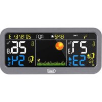
ME 3P20 RC - Weather Station Trevi - Free user manual and instructions
Find the device manual for free ME 3P20 RC Trevi in PDF.



| Product type | Weather station |
| Brand | Trevi |
| Model | ME 3P20 RC |
| Station power supply | 2 AAA 1.5V batteries (not included) or 5V 1A mains adapter included |
| External sensor power supply | 2 AAA 1.5V batteries (not included) |
| Max number of external sensors | 3 (1 provided, 2 optional) |
| Indoor temperature range | -10°C to +50°C |
| Indoor humidity range | 20% to 95% |
| Outdoor temperature range | -40°C to +60°C |
| Sensor transmission | RF 433 MHz, range 30 m, power 10 mW |
| Radio-controlled reception | DCF-77, 77.5 kHz, radius 1500 km |
| Main functions | Radio-controlled clock, alarm, weather forecast (5 icons), MIN/MAX memory, atmospheric pressure, indoor/outdoor temperature/humidity display, backlight |
| Display resolution | 0.1°C for temperature, 1% for humidity |
| Maintenance and cleaning | Clean the exterior with a soft, dry cloth. Do not use abrasive products or solvents. Protect from moisture and magnetic fields. |
| Safety | Do not immerse in water. Keep away from devices generating magnetic fields (phones, televisions). Use only the supplied adapter. |
| Spare parts and repairability | Additional external sensor available as an option. For any repairs, contact a Trevi authorized service center. |
| Warranty | 24 months from the date of manufacture, covers manufacturing defects (excluding wear parts). |
Frequently Asked Questions - ME 3P20 RC Trevi
User questions about ME 3P20 RC Trevi
0 question about this device. Answer the ones you know or ask your own.
Ask a new question about this device
Download the instructions for your Weather Station in PDF format for free! Find your manual ME 3P20 RC - Trevi and take your electronic device back in hand. On this page are published all the documents necessary for the use of your device. ME 3P20 RC by Trevi.
USER MANUAL ME 3P20 RC Trevi
B1. Tasto SET/AL SET
B2. Tasto UP/CH
B3. Tasto MEM
B4. Tasto BARO
B5. Tasto DOWN/RCC
B6. Tasto C/F / BL
B7. Tasto RST
Trasmissione: 30m, RF 433MHz, 10mW
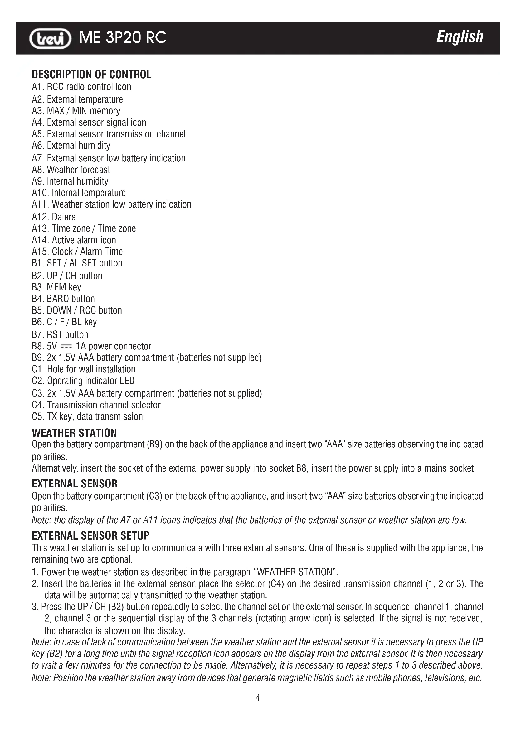
A1. RCC radio control icon
A2. External temperature
A3. MAX / MIN memory
A4. External sensor signal icon
A5. External sensor transmission channel
A6. External humidity
A7. External sensor low battery indication
A8. Weather forecast
A9. Internal humidity
A10. Internal temperature
A11. Weather station low battery indication
A12. Daters
A13. Time zone / Time zone
A14. Active alarm icon
A15. Clock / Alarm Time
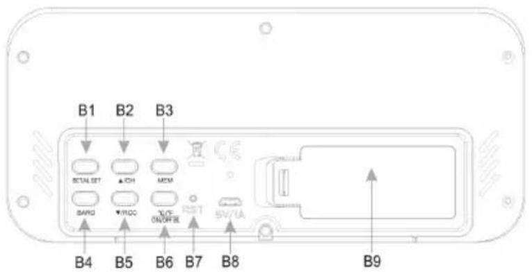
B1. SET / AL SET button
B2. UP / CH button
B3. MEM key
B4. BARO button
B5. DOWN / RCC button
B6. C / F / BL key
B7. RST button
B8. 5V --- 1A power connector
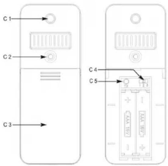
C1. Hole for wall installation
C2. Operating indicator LED
C4. Transmission channel selector
C5. TX key, data transmission
B9. 2x 1.5V AAA battery compartment (batteries not supplied)
C3. 2x 1.5V AAA battery compartment (batteries not supplied)
WEATHER STATION
Open the battery compartment (B9) on the back of the appliance and insert two “AAA” size batteries observing the indicated polarities.
Alternatively, insert the socket of the external power supply into socket B8, insert the power supply into a mains socket.
EXTERNAL SENSOR
Open the battery compartment (C3) on the back of the appliance, and insert two “AAA” size batteries observing the indicated polarities.
Note: the display of the A7 or A11 icons indicates that the batteries of the external sensor or weather station are low.
EXTERNAL SENSOR SETUP
This weather station is set up to communicate with three external sensors. One of these is supplied with the appliance, the remaining two are optional.
- Power the weather station as described in the paragraph "WEATHER STATION".
- Insert the batteries in the external sensor, place the selector (C4) on the desired transmission channel (1, 2 or 3). The data will be automatically transmitted to the weather station.
- Press the UP / CH (B2) button repeatedly to select the channel set on the external sensor. In sequence, channel 1, channel 2, channel 3 or the sequential display of the 3 channels (rotating arrow icon) is selected. If the signal is not received, the character is shown on the display.
Note: in case of lack of communication between the weather station and the external sensor it is necessary to press the UP key (B2) for a long time until the signal reception icon appears on the display from the external sensor. It is then necessary to wait a few minutes for the connection to be made. Alternatively, it is necessary to repeat steps 1 to 3 described above.
Note: Position the weather station away from devices that generate magnetic fields such as mobile phones, televisions, etc.
TIME DISPLAY BY RADIO CONTROL
This device is equipped with a receiver capable of receiving the time signal of the Physikalisch Technische Bundesanstalt Braunschweig (central Germany) receivable within a radius of 1500Km.
- Press and hold the DOWN / RCC button (B5) of the weather station, the symbol (A1) of the radio control will flash and within 24 hours the time signal of the radio control will be displayed.
This weather station is also equipped with DST function, automatic correction of daylight saving time via radio control.
Note1: when the flashing radio control symbol appears on the display, no manual adjustment is possible.
Note2: when the symbol remains on, it means that the signal has been correctly received.
Note3: the time is transmitted from central Germany, so if we are in a country with a different time than Germany it is necessary to set the time zone manually.
Note4: position the weather station away from devices that generate magnetic fields such as mobile phones, televisions, etc.
Not all areas of Europe may be able to receive the radio control signal. In this case it is necessary to set the time manually.
CLOCK MANUAL ADJUSTMENT
- Press and hold the SET button (B1) to enter manual clock adjustment.
- Set the UTC correction of the time zone of your region using the UP (B2) or DOWN (B5) keys. It is possible to select between -1, 0, +1 (this setting is used to correctly receive the time from radio control, for Italy select 0).
- Press the SET button (B1), the display will start to flash in 12/24 hours on the display.
- Set the time display in 12/24 hours using the UP (B2) or DOWN (B5) keys.
- Press the SET button (B1), the hours will start to flash on the display.
- Set the hours using the UP (B2) or DOWN (B5) keys.
- Press the SET button (B1), the minutes will start to flash on the display.
- Set the minutes using the UP (B2) or DOWN (B5) keys.
- Press the SET button (B1), the year will begin to flash on the display.
- Set the year using the UP (B2) or DOWN (B5) keys.
- Press the SET button (B1), the month will begin to flash on the display.
- Set the month using the UP (B2) or DOWN (B5) keys.
- Press the SET button (B1), the day will begin to flash on the display.
- Set the day using the UP (B2) or DOWN (B5) keys.
- Press the SET key (B1), the language in which you want to display the current day will start to flash on the display.
- Set the language using the UP (B2) or DOWN (B5) keys.
- Press the SET button (B1) to end manual clock adjustment.
ALARM ADJUSTMENT
- Press the SET button (B1) once to display the Alarm (A15). Press it again to return to displaying the current time.
- While the alarm is displayed, keep the SET key (B1) pressed, the alarm time on the display starts to flash.
- Press the UP (B2) or DOWN (B5) keys to adjust the time.
- Press the SET button (B1), the minutes of the alarm will start to flash on the display.
- Press the UP (B2) or DOWN (B5) keys to set the minutes.
- Press the SET button (B1) to end the alarm adjustment.
- To activate the alarm, press the SET button (B1); while the alarm is displayed, press the UP (B2) or DOWN (B5) keys. A bell icon (A14) will appear to indicate that the alarm is active.
- To turn off the alarm ringtone, press any key. If not deactivated, the ringer automatically turns off after 2 minutes.
WEATHER FORECAST
The digital barometer automatically detects changes in atmospheric pressure and consequently displays the weather forecast symbol (A8). This forecast concerns the following 12/24 hours.
For example: if the barometer detects a high pressure, the sun symbol will appear on the display, but outside it may rain, because the forecast is for the next 12/24 hours.
Weather forecasts can take 5 different views:

Sunny StormyRainyCloudyPartly claudy
N.B. Weather forecast symbols may not reflect current weather conditions. They refer only to future conditions.
Forecasts may not be 100% safe due to various factors.
The manufacturer is not responsible for any damage or situations caused by an incorrect forecast.
TEMPERATURE AND INTERNAL / EXTERNAL HUMIDITY - MIN / MAX VALUES - BAROMETRIC PRESSURE
In the IN box (on the right) the temperature and internal humidity are indicated, in the OUT box (on the left) the temperature and humidity indicated by the external sensor is indicated.
Press the C / F (B6) button to select the temperature unit in °C or °F.
Minimum / maximum values of the day: press the MEM key (B3), the display shows the maximum temperature / humidity value recorded during the day; press the MEM key (B3) again, the minimum temperature / humidity value is shown.
While displaying the minimum / maximum values, pressing the MEM key (B3) for a long time deletes the recorded data and starts a new calculation of the average daily values.
Atmospheric pressure value: press the BARO key (B4), in the A15 and A13 box the current pressure value hPa will be displayed. Press the BARO button (B4) again to return to the date display.
By long pressing the BARO key (B4) it is possible to adjust the atmospheric pressure value to obtain a better indication of the weather forecast.
ADJUSTMENT OF THE BACKLIGHT
With battery power the backlight of the display is activated every time a key is pressed and then it turns off automatically after 8 seconds.
With power supply from external power supply, the backlight is always active; press the BL key (B6) for a long time until you hear a beep to activate the automatic backlight turn-off after 8 seconds. Press it again a long time to reactivate the backlight always on.
RESTORATION OF THE WEATHER STATION
In the event of abnormal operation, press the RST key (B7) to restore correct operation (the settings made will be lost).
TECHNICAL DATA
Weather station: ....from -10 °C to + 50 °C
Internal humidity: .... from 20% to 95%
External sensor: from -40 °C to +60 °C
Channels: max. 3 external sensors
Radio control signal reception: 77.5 KHz
Transmission: 30m, RF 433MHz, 10mW
Unit feed rate: 0.1 °C for temperature - 1% for humidity
Main unit power supply: 2xAAA batteries (not supplied)
230V \~ 50Hz / 5V = 1A power supply included
External sensor power supply: 2xAAA batteries (not supplied)
DESCRIPTION DES COMMANDES
EXTERNAL SENSOR SETUP
Precautions for correct disposal of the product
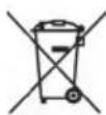
The symbol shown on the equipment indicates that waste must be disposed of in “separate collection” and so the product must not be disposed of together with urban waste.
The user must take the product to special “separate waste collection centres” provided by local government, or deliver it to the retailer against the purchase of a new product.
Separate collection of waste and subsequent treatment, recycling and disposal operations promotes the production of equipment with recycled materials and limits negative effects on the environment and on health caused by improper handling of waste.
Illegal disposal of the product leads to the enforcement of administrative penalties.

- This unit is guaranteed for a period of 24 months from the date of production printed on the product itself or on label on product.
- The warranty is valid only if the unit has not been tampered with. The warranty is valid only at authorized TREVI assistance centres, that will repair manufacturing defects, excluded replacement of labels and removable parts.
- TREVI is not liable for damage to people or things caused by the use of this unit or by the interruption in the use of this unit.
GARANTIE
SIMPLIFIED EU DECLARATION OF CONFORMITY
Hereby TREVI Spa declares that the radio equipment type ME 3P20 RC is in compliance with directive 2014 / 53 / EU.
The full text of the EU declaration of conformity is available at the following internet address https://www.trevi.it/dms/zidi/TREVI/DOCME3P20RC.pdf


- WEATHER STATION
- EXTERNAL SENSOR
- EXTERNAL SENSOR SETUP
- TIME DISPLAY BY RADIO CONTROL
- CLOCK MANUAL ADJUSTMENT
- ALARM ADJUSTMENT
- WEATHER FORECAST
- TEMPERATURE AND INTERNAL / EXTERNAL HUMIDITY - MIN / MAX VALUES - BAROMETRIC PRESSURE
- ADJUSTMENT OF THE BACKLIGHT
- RESTORATION OF THE WEATHER STATION
- TECHNICAL DATA
- DESCRIPTION DES COMMANDES
- Precautions for correct disposal of the product
- GARANTIE
- SIMPLIFIED EU DECLARATION OF CONFORMITY
Brand : Trevi
Model : ME 3P20 RC
Category : Weather Station