
Graphite 380T - Desktop Computer CORSAIR - Free user manual and instructions
Find the device manual for free Graphite 380T CORSAIR in PDF.
| Product Type | Mini-ITX Portable PC Case |
| Brand and Model | CORSAIR Graphite 380T |
| Motherboard Form Factor | Mini-ITX |
| Dimensions (L x W x H) | 393 x 292 x 356 mm |
| Weight | 5.4 kg |
| Maximum Graphics Card Length | 290 mm |
| Maximum CPU Cooler Height | 150 mm |
| Maximum Power Supply Length | 160 mm (ATX) |
| Included Fans | 1 x 120 mm (front) |
| Fan Mounts (max) | Front: 2 x 120 mm / 1 x 140 mm / 1 x 200 mm; Rear: 1 x 120 mm; Side: 2 x 120 mm |
| Front Panel Connectors | 2 x USB 3.0, microphone jack, headphone jack |
| Drive Bays | 1 tool-free 2.5" SSD cage, 1 tool-free 3.5" HDD cage (SSD compatible), 2 trays |
| Carrying Handle | Integrated |
| Side Panel | Windowed with locking mechanism |
| Dust Filters | Bottom filter for power supply |
| Fan Controller | Integrated, 3 speeds, accessible from front panel |
| Component Installation | Tool-free for drives, quick-lock side panels |
| Maintenance and Cleaning | Remove side panels, clean dust filters and front grille |
| Safety | Observe polarity of LED connectors; use provided screws |
| Spare Parts and Repairability | Contact support via corsair.force.com for RMA |
Frequently Asked Questions - Graphite 380T CORSAIR
User questions about Graphite 380T CORSAIR
0 question about this device. Answer the ones you know or ask your own.
Ask a new question about this device
Download the instructions for your Desktop Computer in PDF format for free! Find your manual Graphite 380T - CORSAIR and take your electronic device back in hand. On this page are published all the documents necessary for the use of your device. Graphite 380T by CORSAIR.
USER MANUAL Graphite 380T CORSAIR
© 2014 Corsair Components, Inc.
All rights reserved. Corsair, the sails logo, and Graphite Series are registered trademarks of Corsair in the United States and/or other countries. All other trademarks are the property of their respective owners. Product may vary slightly from those pictured.
PN: 49-001248 rev AA


natural_image
Line drawing of a modern kitchen appliance with control panel and door (no text or symbols)INSTALLATION GUIDE ■ GUIDE D'INSTALLATION INSTALLATIONSANLEITUNG ■ GUIDA ALL'INSTALLAZIONE Guía de Instalación ■ РУКОВОДСТВО ПО УСТАНОВКЕ ■ 安装指南
English: 1-10
Français: 11-20
Italiano: 21-30
Deutsch: 31-40
Español: 41-50
Россию: 51-60
中文: 61-70

GRAPHITE SERIES 380T
Table of Contents
| Congratulations: | 1 |
| Case specifications: | 2 |
| Accessory kit contents: | 3 |
| Case features: | 4 |
| Remove the side panels: | 5 |
| Installing the motherboard: | 5 |
| Installing the PSU: | 6 |
| Installing PCI-E/PCI card(s): | 6 |
| Installing a 2.5" SSD: | 7 |
| Installing a 3.5" HDD: | 7 |
| Powering the Case Fans: | 8 |
| Installing the Front I/O Connectors: | 8 |
| Frequently asked questions: | 9 |
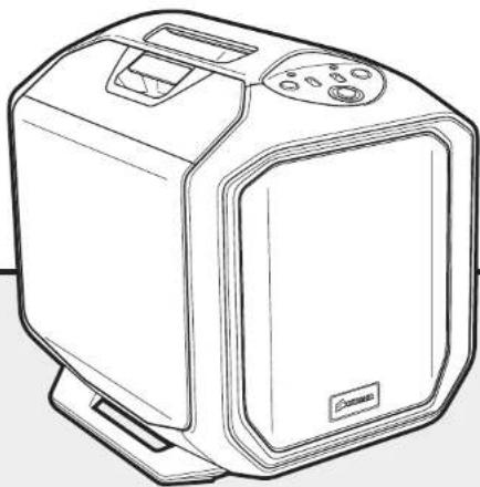
Congratulations!
Thank you for purchasing the Graphite Series 380T Mini-ITX Portable PC Case.
The Graphite Series 380T packs a powerful punch in a portable Mini-ITX PC case. A built-in carrying handle makes transport a breeze. It's easy to build the road-ready computer of your dreams within a spacious, easy to access interior with room for an extra-long graphics card. You can keep things cool with mounts for up to five fans and a convenient front panel three-speed fan controller.
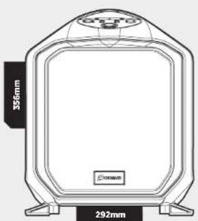
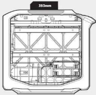
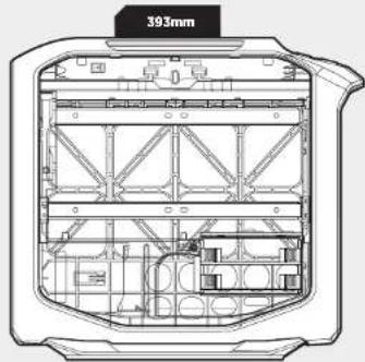
Case Specifications
| Length: | 393mm |
| Width: | 292mm |
| Height: | 356mm |
| Weight: | 5.4kg |
| Maximum GPU Length Top Slots: | 290mm |
| Maximum GPU Length All Slots: | 290mm |
| Maximum CPU cooler height: | 150mm |
| Maximum PSU length: | 160mm |

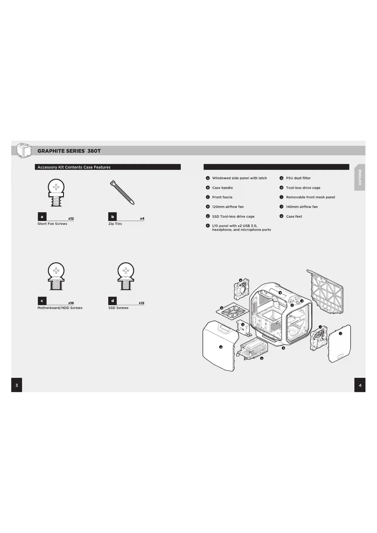
GRAPHITE SERIES 380T
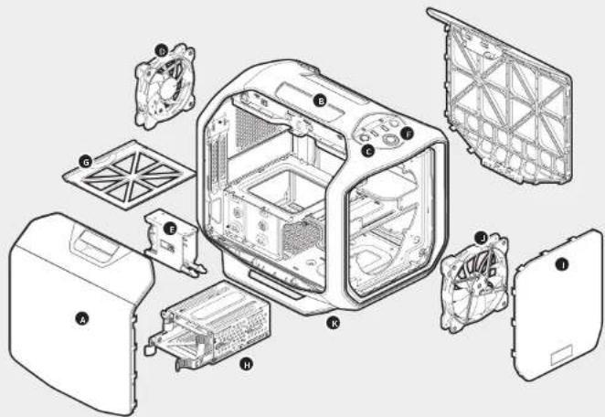
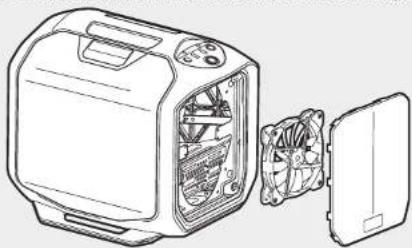
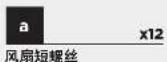
Accessory Kit Contents Case Features


A Windowed side panel with latch
B Case handle
Front fascia
120mm airflow fan
F SSD Tool-less drive cage
F I/O panel with x2 USB 3.0, headphone, and microphone ports
PSU dust filter
Tool-less drive cage
Removable front mesh panel
140mm airflow fan
Case feet

GRAPHITE SERIES 380T
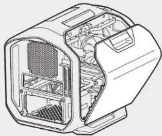
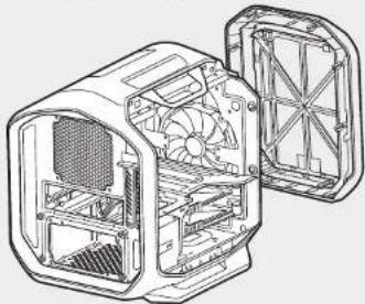
1. Remove the Side Panel
Simply pull upward on the side panel latches to release.
Note: Corsair recommends removing both side panels and setting them aside when building your system to avoid accidental damage. Both side panels are interchangeable and should be removed to reduce clutter.
natural_image
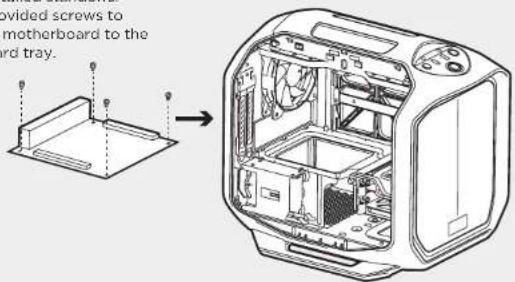
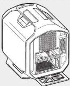
Technical line drawing of a computer case with internal components (no text or symbols)2. Installing the Motherboard
First, install your motherboard's I/O shield (see your motherboard's manual for guidance).
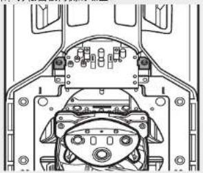
Align your motherboard with the pre-installed standoffs. Use the provided screws to secure the motherboard to the motherboard tray.
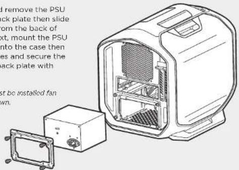
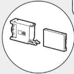
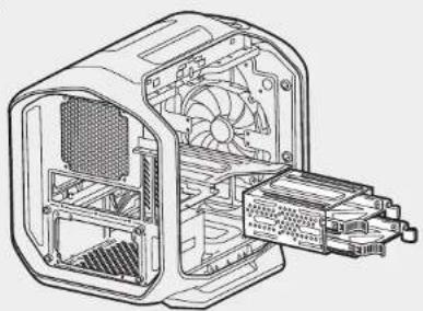
3. Installing the PSU
Unscrew and remove the PSU mounting back plate then slide in the PSU from the back of the case. Next, mount the PSU back plate onto the case then align the holes and secure the PSU to the back plate with screws.
Note: PSU must be installed fan side facing down.
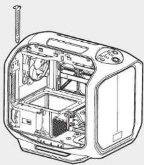
4. Installing PCI-E/PCI Card(s)
Remove thumbscrews and corresponding slot cover(s).
Install the add-on card and secure with thumbscrews.
natural_image
Technical line drawing of a microwave oven with internal components and ventilation duct (no text or labels)
GRAPHITE SERIES 380T
5. Installing a 2.5" SSD
Pull down the tab and place the SSD into the tool-free cage until you feel it secure. To remove the SSD, pull the tab down to release.
Note: To remove the SSD from the cage, simply pull the tab down to release.
natural_image
Simple line drawing of a mechanical component and a rectangular block inside a circle (no text or symbols)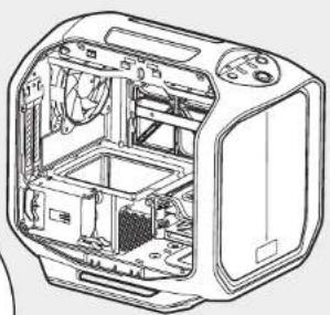
natural_image
Cross-sectional diagram of a toaster oven showing internal components and casing (no text or labels)6. Installing a 3.5" HDD
Remove the tool-free 3.5" HDD tray from the drive cage, then insert the HDD into the HDD tray. Next, align the HDD holes with tray pins to secure and insert the drive tray back into the cage.
Note: This drive cage is also SSD compatible, so you can install a 2.5" SSD into the SSD tray.
natural_image
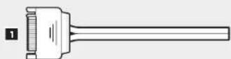
Technical line drawing of an internal computer case with fan and drive components (no text or symbols)7. Powering the Case Fans
- Connect the SATA power connector to the PSU SATA power cable.
- Connect the 3 or 4-Pin fan connector to the case fan header.
- Push the fan speed selector button on your case to toggle fan speed.
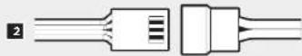

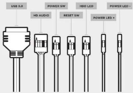
8. Installing the Front I/O Connectors
See your motherboard's manual for front panel header locations and pin-outs.

GRAPHITE SERIES 380T
Frequently Asked Questions
1. How do I remove the I/O Panel?
A. To remove the front fascia, push in the tabs from inside the fascia, then push towards the front of the case.
natural_image
Technical line drawing of a mechanical device showing internal fan structure (no text or symbols)B. unscrewing the 2 screws at each side of panel.
natural_image
Technical line drawing of a mechanical assembly with no visible text or symbols- Does the polarity matter with the I/O panel's power and reset header? No, only the LED headers.
-
Who should I contact if I received my case damaged or one of the fans is no longer working? Please go to corsair.force.com and request an RMA so that we can replace the damaged part(s).
-
Where can I mount a fan?
| Fan Mount Locations | |
| Front 2 x 120mm, 1 x 140mm, 1 x 200mm | |
| Top x | |
| Rear 1 x 120mm | |
| Bottom x | |
| Side 2 x 120mm | |
| Mid x | |
5. How do I remove the front panel?
To remove the front panel, push the top corners of the plastic cover.
natural_image
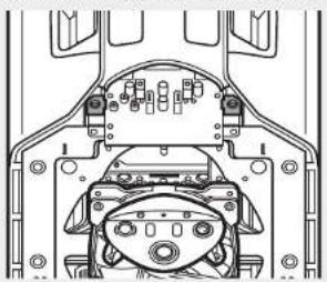
Line drawing of a computer tower with internal fan and cooling unit (no text or symbols)6. How do I remove the bottom PSU filter(s)?
To remove the bottom dust filter, first locate the pull out tab underneath the PSU, then pull the bottom dust filter out.
natural_image
Technical line drawing of a mechanical device with internal compartments and mounting base (no text or symbols)To learn more about this case visit the product page at corsair.com

GRAPHITE SERIES 380T
Table des matières

GRAPHITE SERIES 380T

GRAPHITE SERIES 380T
natural_image
Technical line drawing of a computer case with internal components (no text or symbols)natural_image
Technical line drawing of an open microwave oven with internal components and mounting base (no text or symbols)natural_image
Technical line drawing of a microwave oven with internal components and ventilation duct (no text or labels)
GRAPHITE SERIES 380T
natural_image
Simple line drawing of a box and a rectangular block inside a circle (no text or symbols)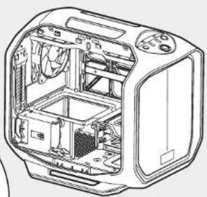
natural_image
Technical line drawing of a toaster oven showing internal components and casing (no text or labels)natural_image
Technical line drawing of an internal computer case with fan and heatsink (no text or symbols)natural_image
Technical line drawing of an internal combustion engine housing with fan and cooling fins (no text or symbols)natural_image
Technical line drawing of a mechanical assembly with no visible text or symbolsnatural_image
Line drawing of a computer oven with internal fan and cooling unit (no text or symbols)natural_image
Line drawing of a device casing with internal compartments and mounting base (no text or symbols)

GRAPHITE SERIES 380T

GRAPHITE SERIES 380T
natural_image
Technical line drawing of a computer case with internal components (no text or symbols)natural_image
Technical line drawing of a microwave oven with internal components and ventilation duct (no text or labels)
GRAPHITE SERIES 380T
natural_image
Simple line drawing of a box and a rectangular block inside a circle (no text or symbols)
natural_image
Technical line drawing of a toaster oven showing internal components and casing (no text or labels)natural_image
Technical line drawing of an internal computer case with fan and heatsink (no text or symbols)natural_image
Technical line drawing of a device interior showing internal fan structure (no text or symbols)natural_image
Technical line drawing of a mechanical assembly with no visible text or symbolsnatural_image
Line drawing of a computer oven with internal fan and cooling unit (no text or symbols)natural_image
Line drawing of a mechanical device with internal compartments and mounting base (no text or symbols)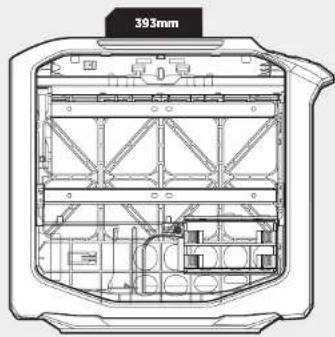

GRAPHITE SERIES 380T

GRAPHITE SERIES 380T
natural_image
Technical line drawing of a computer case with internal components (no text or symbols)2. Installation des Mainboards
natural_image
Technical line drawing of a microwave oven with internal components and a screwdriver (no text or labels)
GRAPHITE SERIES 380T
5. Installation des 2,5-Zoll SSD
natural_image
Simple line drawing of a box and a rectangular block inside a circle (no text or symbols)
natural_image
Technical line drawing of a toaster oven showing internal components and casing (no text or labels)natural_image
Technical line drawing of an internal computer case with fan and heatsink (no text or symbols)natural_image
Technical line drawing of a mechanical device showing internal fan structure (no text or symbols)natural_image
Technical line drawing of a vehicle chassis frame with no visible text or symbolsnatural_image
Line drawing of a computer tower with internal fan and cooling unit (no text or symbols)natural_image
Technical line drawing of a device casing with internal compartments and mounting base (no text or symbols)

GRAPHITE SERIES 380T

GRAPHITE SERIES 380T
natural_image
Technical line drawing of a computer case with internal components (no text or symbols)natural_image
Technical line drawing of a microwave oven with internal components and ventilation duct (no text or labels)
GRAPHITE SERIES 380T
natural_image
Simple line drawing of a box and a panel inside a circle (no text or symbols)
natural_image
Technical line drawing of a toaster oven showing internal components and casing (no text or labels)natural_image
Technical line drawing of an internal computer case with fan and drive components (no text or symbols)natural_image
Technical line drawing of a computer case with fan and ventilation slots (no text or symbols)natural_image
Technical line drawing of a mechanical assembly with no visible text or symbolsnatural_image
Line drawing of a computer oven with internal fan and cooling unit (no text or symbols)natural_image
Technical line drawing of a mechanical device housing (no text or symbols)

GRAPHITE SERIES 380T

GRAPHITE SERIES 380T
natural_image
Technical line drawing of a computer case with internal components (no text or symbols)natural_image
Technical line drawing of a microwave oven with internal components and ventilation duct (no text or labels)
GRAPHITE SERIES 380T
natural_image
Simple line drawing of a box and a flatboard inside a circle (no text or symbols)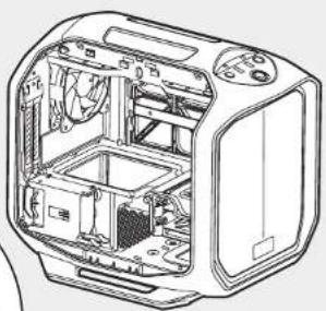
natural_image
Technical line drawing of a toaster oven showing internal components and casing (no text or labels)natural_image
Technical line drawing of an internal computer case with fan and heatsink (no text or symbols)natural_image
Technical line drawing of an internal combustion engine housing with fan and cooling fins (no text or symbols)natural_image
Technical line drawing of a mechanical assembly with no visible text or symbolsnatural_image
Line drawing of a computer tower with internal fan and cooling unit (no text or symbols)natural_image
Line drawing of a device casing with internal compartments and mounting base (no text or symbols)

GRAPHITE SERIES 380T
配件目录 机箱特点


GRAPHITE SERIES 380T
1.拆卸侧面板
只需向上拉侧面板弹簧锁即可释放侧面板。
natural_image
Technical line drawing of a computer case with internal components (no text or symbols)2. 安装主板
natural_image
Technical line drawing of an open microwave oven with internal components and mounting base (no text or symbols)3. 安装PSU
natural_image
Line drawing of a microwave oven internal structure showing internal components and casing (no text or labels)
GRAPHITE SERIES 380T
5. 安装 2.5 英寸 SSD
natural_image
Simple line drawing of a box and a flatboard inside a circle (no text or symbols)
natural_image
Technical line drawing of a toaster oven showing internal components and casing (no text or labels)6. 安装 3.5 英寸 SSD
natural_image
Technical line drawing of an internal computer case with fan and drive components (no text or symbols)7. 连接机箱风扇电源
natural_image
Technical line drawing of an internal combustion engine housing with fan blades and cooling fins (no text or symbols)B. 接下来,拧松面板两侧的螺丝。
natural_image
Technical line drawing of a vehicle chassis frame with no visible text or symbols- 极性是否影响 I/O 面板电源和重置接头?
不,仅影响LED接头。
natural_image
Line drawing of a computer case with internal fan and cooling unit (no text or symbols)- 如何拆下底部滤尘器?
natural_image
Technical line drawing of a device casing with internal compartments and mounting base (no text or symbols)
- GRAPHITE SERIES 380T
- Congratulations!
- Thank you for purchasing the Graphite Series 380T Mini-ITX Portable PC Case.
- Accessory Kit Contents Case Features
- Remove the Side Panel
- Installing the Motherboard
- Installing the PSU
- Installing PCI-E/PCI Card(s)
- Installing a 2.5" SSD
- Installing a 3.5" HDD
- Powering the Case Fans
- Installing the Front I/O Connectors
- Frequently Asked Questions
- How do I remove the I/O Panel?
- How do I remove the front panel?
- How do I remove the bottom PSU filter(s)?
- Installation des Mainboards
- Installation des 2,5-Zoll SSD
- 配件目录 机箱特点
- 1.拆卸侧面板
- 安装主板
- 安装PSU
- 安装 2.5 英寸 SSD
- 安装 3.5 英寸 SSD
- 连接机箱风扇电源
Brand : CORSAIR
Model : Graphite 380T
Category : Desktop Computer