
LAN1 - Network cable tester Amprobe - Free user manual and instructions
Find the device manual for free LAN1 Amprobe in PDF.
| Product Type | Network Cable Tester LAN-1 |
| Brand | Amprobe |
| Model | LAN1 |
| Dimensions | 130 x 64 x 38 mm (5.1 x 2.2 x 1.5 inches) |
| Weight | 0.6 kg (1.2 lb) |
| Power Supply | 9 V battery (type 006P, IEC 6F22 or NEDA 1604); battery life approx. 20 hours (alkaline) |
| Main Functions | Continuity test, opens, shorts, and miswired wires; automatic and manual analysis; loop test and remote test; error buzzer; display hold |
| Supported Cable Types | 10/100 base-T, 10 base-2, RJ45, AT&T 258A, EIA/TIA 568A/568B, Token Ring |
| Connectors | RJ45 (input and output), BNC (via supplied cables) |
| Display | Green LED indicators (source) and red (test); low battery indicator |
| Maximum Line Length | 300 meters |
| Safety | Do not use on live circuits; do not expose to moisture; do not use in explosive atmosphere; do not ground yourself |
| Maintenance and Cleaning | Clean with a soft cloth dampened with a mild solution of water and detergent; do not use chlorinated solvents or aromatic hydrocarbons |
| Spare Parts and Repairability | Battery replacement by user; other repairs at authorized center; 1-year warranty |
| Package Contents | LAN-1 tester, remote test module, 9V battery, RJ45-BNC female cable, RJ45-BNC male cable, RJ45-RJ45 cable, BNC female-female connector, user manual |
| General Information | Compliant with CE directives; do not connect to public networks |
Frequently Asked Questions - LAN1 Amprobe
The automatic test continuously scans lines 1 to 8 and ground.
The manual test allows stepping through lines with the TEST button.
- Open: the red LED remains off.
- Short: two red LEDs light up simultaneously (e.g., pins 2 and 3).
- Miswired: red LEDs light on the wrong pins (e.g., pin 2 lit instead of pin 6).
The buzzer sounds in case of an error.
User questions about LAN1 Amprobe
0 question about this device. Answer the ones you know or ask your own.
Ask a new question about this device
Download the instructions for your Network cable tester in PDF format for free! Find your manual LAN1 - Amprobe and take your electronic device back in hand. On this page are published all the documents necessary for the use of your device. LAN1 by Amprobe.
USER MANUAL LAN1 Amprobe
© 2008 Amprobe Test Tools.
All rights reserved.
Limited Warranty and Limitation of Liability
Your Amprobe product will be free from defects in material and workmanship for 1 year from the date of purchase. This warranty does not cover fuses, disposable batteries or damage from accident, neglect, misuse, alteration, contamination, or abnormal conditions of operation or handling. Resellers are not authorized to extend any other warranty on Amprobe's behalf. To obtain service during the warranty period, return the product with proof of purchase to an authorized Amprobe Test Tools Service Center or to an Amprobe dealer or distributor. See Repair Section for details. THIS WARRANTY IS YOUR ONLY REMEDY. ALL OTHER WARRANTYES - WHETHER EXPRESS, IMPLIED OR STAUTORY - INCLUDING IMPLIED WARRANTY OF FITNESS FOR A PARTICULAR PURPOSE OR MERCHANTABILITY, ARE HEREBY DISCLAIMED. MANUFACTURER SHALL NOT BE LIABLE FOR ANY SPECIAL, INDIRECT, INCIDENTAL OR CONSEQUENTIAL DAMAGES OR LOSSES, ARISING FROM ANY CAUSE OR THEORY. Since some states or countries do not allow the exclusion or limitation of an implied warranty or of incidental or consequential damages, this limitation of liability may not apply to you.
Repair
All test tools returned for warranty or non-warranty repair or for calibration should be accompanied by the following: your name, company's name, address, telephone number, and proof of purchase. Additionally, please include a brief description of the problem or the service requested and include the test leads with the meter. Non-warranty repair or replacement charges should be remitted in the form of a check, a money order, credit card with expiration date, or a purchase order made payable to Amprobe® Test Tools.
In-Warranty Repairs and Replacement – All Countries
Please read the warranty statement and check your battery before requesting repair. During the warranty period any defective test tool can be returned to your Amprobe® Test Tools distributor for an exchange for the same or like product. Please check the "Where to Buy" section on www.amprobe.com for a list of distributors near you. Additionally, in the United States and Canada In-Warranty repair and replacement units can also be sent to a Amprobe® Test Tools Service Center (see address below).
Non-Warranty Repairs and Replacement - US and Canada
Non-warranty repairs in the United States and Canada should be sent to a Amprobe® Test Tools Service Center. Call Amprobe® Test Tools or inquire at your point of purchase for current repair and replacement rates.
In USA In Canada
Amprobe Test Tools Amprobe Test Tools
Everett, WA 98203 Mississauga, ON L4Z 1X9
Tel: 877-AMPROBE (267-7623) Tel: 905-890-7600
Non-Warranty Repairs and Replacement - Europe
European non-warranty units can be replaced by your Amprobe® Test Tools distributor for a nominal charge. Please check the "Where to Buy" section on www.amprobe.com for a list of distributors near you.
European Correspondence Address*
Amprobe Test Tools Europe
In den Engematten 14
79286 Glottertal, Germany
Tel.: +49 (0) 7684 8009 - 0
*Correspondence only - no repair or replacement available from this address.
European customers please contact your distributor.)
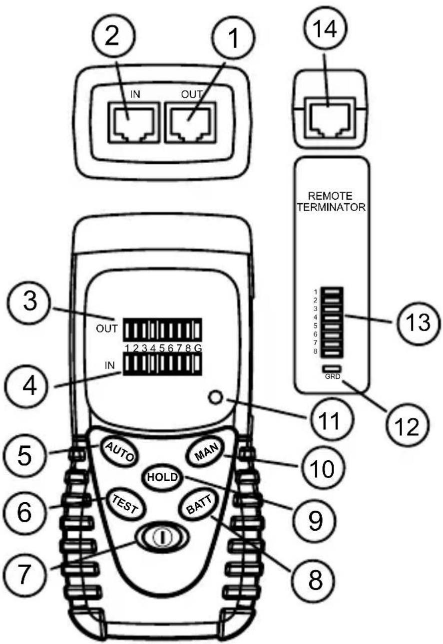
RJ45 jack for sourcing end (OUT).
RJ45 jack for receiving end (IN).
3 LED indicators for sourcing end (OUT) Green.
LED indicators for receiving end (IN). Red.
AUTO scan button.
TEST button for MANUAL test.
7 POWER ON/OFF button.
BATTERY TEST button.
HOLD button.
10 MANual scan button.
Low BATTERY indicator.
Remote Terminator LED indicator for ground wire
Remote Terminator LED indicators for data lines
Remote Terminator RJ45 jack
CONTENTS
Symbols 5
Unpacking and Inspection 5
Introduction. 5
Operation 6
Loopback Test (cable with both ends in one location) 6
Remote Test (cable with both ends at different locations) 6
Hold 6
Test Examples 7
Specifications 7
Maintenance and Repair 8
Battery Replacement 8
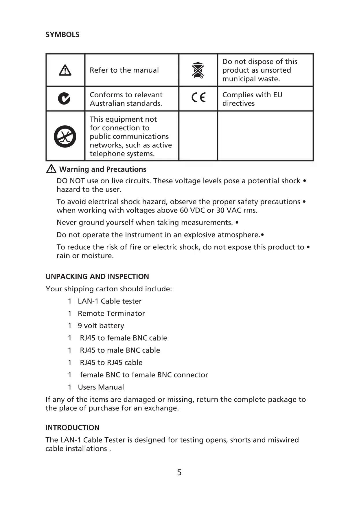
| ! | Refer to the manual | ® | Do not dispose of this product as unsorted municipal waste. |
| C | Conforms to relevant Australian standards. | C€ | Complies with EU directives |
| × | This equipment not for connection to public communications networks, such as active telephone systems. |

Warning and Precautions
DO NOT use on live circuits. These voltage levels pose a potential shock - hazard to the user.
To avoid electrical shock hazard, observe the proper safety precautions when working with voltages above 60 VDC or 30 VAC rms.
Never ground yourself when taking measurements.
Do not operate the instrument in an explosive atmosphere.
To reduce the risk of fire or electric shock, do not expose this product to rain or moisture.
UNPACKING AND INSPECTION
Your shipping carton should include:
1 LAN-1 Cable tester
1 Remote Termination
1 9 volt battery
1 RJ45 to female BNC cable
1 RJ45 to male BNC cable
1 RJ45 to RJ45 cable
1 female BNC to female BNC connector
1 Users Manual
If any of the items are damaged or missing, return the complete package to the place of purchase for an exchange.
INTRODUCTION
The LAN-1 Cable Tester is designed for testing opens, shorts and miswired cable installations.
Testing capabilities are:
Test pin configuration for 10/100 base -T cable, 10 base-2 cable, RJ45 • modular cables, AT&T 258A cable, EIA / TIA 568A/568B cables and Token Ring Cable etc.
Verify cable continuity, open, short or incorrectly wired.
Test installed cable on wall plate or the patch panels by using the Remote Termination module.
Buzzer sound warning for error condition.
OPERATION
Press 1. ① button for power ON. If no cable is attached or cable is defective, the buzzer will sound.
Press BATT to verify proper operating voltage. The BATT LED will not light 2. and LAN-1 will not operate correctly if battery is below 7 volts.
Green LEDs are the source indicators. Red LED's are the test indicators. 3. Red LED's ON indicate cable line continuity. Red LED's OFF indicate open cable lines.
Loopback Test (cable with both ends in one location)
Connect cable with RJ-45 terminations on both ends to IN and OUT test 1. sockets.
Press 2. ① button for power ON. Press AUTO (default) or MAN button to start scanning.
AUTO scanning will step through lines 1 to 8 and ground (if connected) 3. and repeats until stopped.
MAN scanning will go into manual mode and TEST will step through the 4. different lines.
Remote Test (cable with both ends at different locations)
Connect one cable end to OUT connector.1.
Connect REMOTE TERMINATOR to the other end of cable under test.2.
Press 3. ① button for power ON. Press AUTO (default) or MAN button to start scanning.
AUTO scanning will step through lines 1 to 8 and ground (if connected) 4. and repeat until stopped.
MAN scanning go into manual mode and TEST will step through the 5. different lines.
Line test results (Red LED's) are shown on the Remote Terminator.6.
Hold
The HOLD button saves the displayed error condition and stops testing. Press the HOLD button to return to normal operation.
TEST EXAMPLES
Continuity Green
Pin 2 has continuity 1 2 3 4 5 6 7 8 G
Red
Open Green
Pin 2 is open 1 2 3 4 5 6 7 8 G
Red 中 中 中 中 中 中 中 中 中 中 中 中 中 中 中 中 中 中 中 中 中 1 中 中 中 中 中 中 中 中 中 中 中 中 中 中 中 中 中 中 中 中 中 中 中 中 中 中 中 中 中 中 中 中 中 中 中 中 中 中 中 中
Short Green
Pins 2 and 3 are shorted 1 2 3 4 5 6 7 8 G
Red
Miswire Green
Pins 2 and 6 are miswired 1 2 3 4 5 6 7 8 G
Red
SPECIFICATIONS
General
Display: Red and Green LED's
Battery: 9V, 006P or IEC 6F22 or NEDA 1604.
Low Battery Indicator: The LED indicator will not turn ON when BATT button pushed
Battery Life: Approx 20 hours. (Alkaline battery)
Environment: Indoor operation, maximum altitude - 2000 m (6561 ft.)
Temperature / Humidity:
Operation: 0 to 40^ (32 to 104^ ), 10 to 70% RH.
Storage: -10 to 60^ (14 to 140^ ), 10 to 90% RH.
Dimension: 130 × 64 × 38mm (5.1 x 2.2 x 1.5 in)
Weight: 1.26kg (0.6 lb)
CE-EMC: EN61326-1 This product complies with requirements of the following European Community Directives: 89/336/EEC (Electromagnetic Compatibility) and 73/23/EEC (Low Voltage) as amended by 93/68/EEC (CE Marking). However, electrical noise or intense electromagnetic fields in the vicinity of the equipment may disturb the measurement circuit. Measuring
instruments will also respond to unwanted signals that may be present within the measurement circuit. Users should exercise care and take appropriate precautions to avoid misleading results when making measurements in the presence of electronic interference.
Electrical
Maximum line length: 300 meters
Connector types: RJ45, BNC
DO NOT use on live circuits.
MAINTENANCE AND REPAIR
If there appears to be a malfunction during the operation of the tester, the following steps should be performed in order to isolate the cause of the problem.
Press the BATTERY button to check the battery. Replace the battery 1. immediately if the LED indicator will not turn ON.
Review the operating instructions for possible mistakes in operating 2. procedure.
Except for the replacement of the battery, repair of the meter should be performed only by a Factory Authorized Service Center or by other qualified instrument service personnel. The front panel and case can be cleaned with a mild solution of detergent and water. Apply sparingly with a soft cloth and allow to dry completely before using. Do not use aromatic hydrocarbons or chlorinated solvents for cleaning.
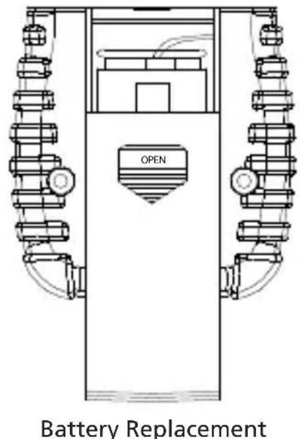
BATTERY REPLACEMENT
- Turn off the meter and slide out the battery cover. Replace the battery with a NEDA type 1604 or equivalent 9V alkaline battery. Replace the cover.
- Remove battery when the LAN-1 is not used for extended period.

LAN-1
© 2008 Amprobe Test Tools.
Amprobe Test Tools Amprobe Test Tools
Everett, WA 98203 E-U Mississauga, Ontario L4Z 1X9 Canada
Tél.: 877-AMPROBE (267-7623) Tél.: 905-890-7600
Amprobe Test Tools Europe
In den Engematten 14
© 2008 Amprobe Test Tools.
Amprobe Test Tools Amprobe Test Tools
Everett, WA 98203 Mississauga, ON L4Z 1X9
Tel.: 877-AMPROBE (267-7623) Tel.: 905-890-7600
Amprobe Test Tools Europe
In den Engematten 14
© 2008 Amprobe Test Tools.
Amprobe Test Tools Amprobe Test Tools
Everett, WA 98203, U.S.A. Mississauga, ON L4Z 1X9 Canada
Tel.: 877-AMPROBE (877 267 7623) Tel.: +1 905 890 7600
Amprobe Test Tools Europe
In den Engematten 14
79286 Glottertal, Germania
Tel.: +49 (0) 7684 8009 - 0
© 2008 Amprobe Test Tools.
Amprobe Test Tools Amprobe Test Tools
Everett, WA 98203 Mississauga, Ontario L4Z 1X9
Tel.: 877-AMPROBE (267-7623) Tel.: 905-890-7600
Amprobe Test Tools Europe
In den Engematten 14
© 2008 Amprobe Test Tools.
Med ensamratt.
Amprobe Test Tools Amprobe Test Tools
Everett, WA 98203 Mississauga, ON L4Z 1X9
Tel: 877-AMPROBE (267-7623) Tel: 905-890-7600
Amprobe Test Tools Europe
In den Engematten 14
79286 Glottertal, Germany
Tel: +49 (0) 7684 8009 - 0
* (Endast correspondens - inga reparationer uller reservdilar kan erhallas fran den har adressen. Kunder i Europa ska kontakta respektive distributor.)

RJ45-jack for strömgenereringsänden (UT).
RJ45-jack for mottagningsänden (IN).
Lampindikatorer for strömgenereringsänden (UT), gröna.
Lampindikatorer for mottagningsänden (IN), röda.
Knappen AUTO for automatisk skanning.
Knappen TEST for manuell testing.
7 Knappen ON/OFF (PA/AV).
Knappen BATT for testing av batteri.
9 Knappen HOLD (HALL)
Knappen MAN for manuell skanning.
11 Indikator for lagt batteri.
Indikator for jordledning pa Fjarrterminator.
Indikatorer for datalinjer pa Fjarrterminator.
14 RJ45-jack på Fjärrterminator.
Visit www.Amprobe.com for
Catalog
Application notes
Product specifications
User manuals
- Limited Warranty and Limitation of Liability
- Repair
- In-Warranty Repairs and Replacement – All Countries
- Non-Warranty Repairs and Replacement - US and Canada
- In USA In Canada
- Non-Warranty Repairs and Replacement - Europe
- European Correspondence Address*
- CONTENTS
- Warning and Precautions
- UNPACKING AND INSPECTION
- INTRODUCTION
- OPERATION
- Loopback Test (cable with both ends in one location)
- Remote Test (cable with both ends at different locations)
- Hold
- TEST EXAMPLES
- SPECIFICATIONS
- General
- Electrical
- MAINTENANCE AND REPAIR
- BATTERY REPLACEMENT
- LAN-1
Brand : Amprobe
Model : LAN1
Category : Network cable tester