
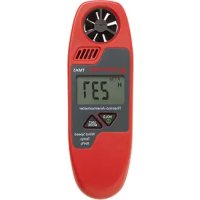
TMA10A - Anemometer Amprobe - Free user manual and instructions
Find the device manual for free TMA10A Amprobe in PDF.
| Product Type | Digital Anemometer |
| Brand | Amprobe |
| Model | TMA10A |
| Display | Dual 4-digit LCD (9999 counts) |
| Main Instrument Dimensions | 181 x 71 x 38 mm |
| Sensor Head Diameter | 70 mm |
| Weight (with battery and sensor) | 363 g |
| Power Supply | 9 V battery (heavy duty alkaline) |
| Battery Life | Approximately 100 hours |
| Measurement Units | Speed: ft/min or m/s; Flow: CFM or CMS; Temperature: °C or °F |
| Air Velocity Measuring Range | 0.40 to 25.00 m/s or 125 to 4900 ft/min |
| Air Flow Measuring Range | 0.01 to 99.99 m³/s or 1 to 9999 ft³/min |
| Temperature Range | 0 to 50 °C (32 to 122 °F) |
| Speed Accuracy | ±2 % of full scale |
| Temperature Accuracy | ±0.8 °C (±1.5 °F) |
| Speed/Flow Sensor | Tilting vane arm with low friction bearing |
| Temperature Sensor | Precision thermistor |
| Main Functions | Air velocity, air flow, temperature measurement; HOLD function; single-point MIN/MAX/AVG recording (max 2 h) and multipoint (8 values); unit selection; auto power off (20 min, can be disabled) |
| Maintenance and Cleaning | Replace 9 V battery; clean with dry cloth |
| Safety | Use between 0 and 50 °C, max RH 80%; do not expose to excessive humidity |
| Spare Parts and Repairability | Sensor and battery replaceable; repair under warranty or charged |
| Warranty | 1 year against defects in materials and workmanship |
| General Information | User manual and instruction guide free in PDF format; 64 pages; available languages |
Frequently Asked Questions - TMA10A Amprobe
User questions about TMA10A Amprobe
0 question about this device. Answer the ones you know or ask your own.
Ask a new question about this device
Download the instructions for your Anemometer in PDF format for free! Find your manual TMA10A - Amprobe and take your electronic device back in hand. On this page are published all the documents necessary for the use of your device. TMA10A by Amprobe.
USER MANUAL TMA10A Amprobe
All rights reserved. Printed in Taiwan
Limited Warranty and Limitation of Liability
Your Amprobe product will be free from defects in material and workmanship for one year from the date of purchase unless local laws require otherwise. This warranty does not cover fuses, disposable batteries or damage from accident, neglect, misuse, alteration, contamination, or abnormal conditions of operation or handling. Resellers are not authorized to extend any other warranty on the behalf of Amprobe. To obtain service during the warranty period, return the product with proof of purchase to an authorized Amprobe Service Center or to an Amprobe dealer or distributor. See Repair Section for details. THIS WARRANTY IS YOUR ONLY REMEDY. ALL OTHER WARRANTIES - WHETHER EXPRESS, IMPLIED OR STATUTORY - INCLUDING IMPLIED WARRANTIES OF FITNESS FOR A PARTICULAR PURPOSE OR MERCHANTABILITY, ARE HEREBY DISCLAIMED. MANUFACTURER SHALL NOT BE LIABLE FOR ANY SPECIAL, INDIRECT, INCIDENTAL OR CONSEQUENTIAL DAMAGES OR LOSSES, ARISING FROM ANY CAUSE OR THEORY. Since some states or countries do not allow the exclusion or limitation of an implied warranty or of incidental or consequential damages, this limitation of liability may not apply to you.
Repair
All Amprobe returned for warranty or non-warranty repair or for calibration should be accompanied by the following: your name, company's name, address, telephone number, and proof of purchase. Additionally, please include a brief description of the problem or the service requested and include the test leads with the meter. Non-warranty repair or replacement charges should be remitted in the form of a check, a money order, credit card with expiration date, or a purchase order made payable to Amprobe.
In-warranty Repairs and Replacement – All Countries
Please read the warranty statement and check your battery before requesting repair. During the warranty period, any defective test tool can be returned to your Amprobe distributor for an exchange for the same or like product. Please check the "Where to Buy" section on amprobe.com for a list of distributors near you. Additionally, in the United States and Canada, in-warranty repair and replacement units can also be sent to an Amprobe Service Center (see address below).
Non-warranty Repairs and Replacement – United States and Canada
Non-warranty repairs in the United States and Canada should be sent to an Amprobe Service Center. Call Amprobe or inquire at your point of purchase for current repair and replacement rates.
USA: Canada:
Amprobe
Amprobe
Everett, WA 98203 Mississauga, ON L4Z 1X9
Tel: 877-AMPROBE (267-7623) Tel: 905-890-7600
Non-warranty Repairs and Replacement – Europe
European non-warranty units can be replaced by your Beha-Amprobe distributor for a nominal charge. Please check the "Where to Buy" section on beha-amprobe.com for a list of distributors near you.
Beha-Amprobe
Division and reg. trademark of Fluke Corp. (USA)
Germany* United Kingdom
In den Engematten 14 52 Hurricane Way
79286 Glottertal Norwich, Norfolk
Germany NR6 6JB United Kingdom
Phone: +49 (0) 7684 8009 - 0 Phone: +44 (0) 1603 25 6662
beha-amprobe.de
beha-amprobe.com
The Netherlands - Headquarters**
Science Park Eindhoven 5110
5692 EC Son
The Netherlands
Phone: +31 (0) 40 267 51 00
beha-amprobe.com
*(Correspondence only – no repair or replacement available from this address. European customers please contact your distributor.)
**single contact address in EEA Fluke Europe BV
Contents
USING THE PUSHBUTTONS....2
DISPLAY INDICATORS....3
MAKING MEASUREMENTS 4
Air Velocity Measurements....4
Air Flow Measurements 4
Single Point MIN/MAX/AVG Recording 5
Multi Point Average Recording ....5
Data Hold Feature 6
Changing the Units of Measure....6
AUTO POWER OFF 7
ERROR MESSAGE DISPLAY....7
USEFUL EQUATIONS AND CONVERSIONS ...... 7
Cubic Equations ...... 7
Units Conversion Table....7
REPLACING THE BATTERY 7
SPECIFICATIONS......8
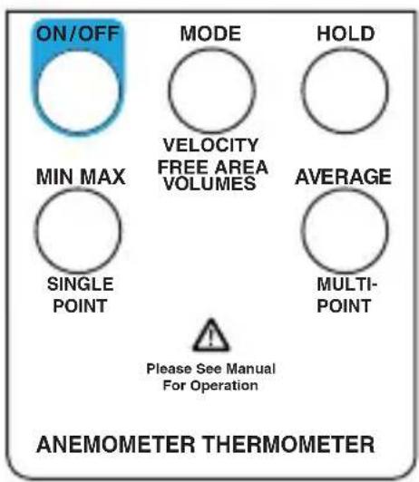
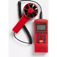
| Button Description | |
| ON/OFF | Turns the meter on and off. |
| MODE | Toggle between velocity, free area, and volume. |
| HOLD | Captures a reading. Sets digit to the desired value. |
| MIN MAX | View the minimum or maximum. Average or record value. |
| AVERAGE | Display the average of all the measurements. Select the next digit for editing. |
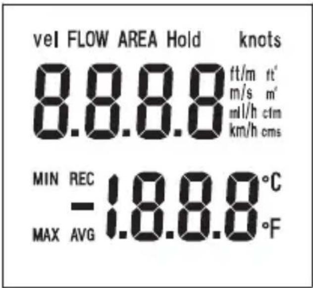
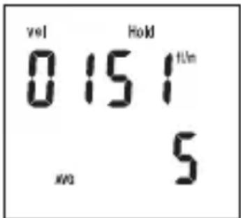
Vel Air velocity measurement.
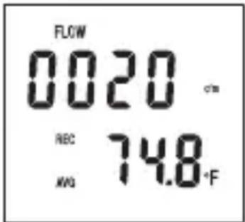
FLOW Air flow/air volumen.
AREA Free area default setting.
Hold Freezes the reading.
knots 1850 meters per hour.
ft/m Feet per minute.
ft2 Square feet.
cfm Cubic feet per minute.
km/h Kilometers per hour.
cms Cubic meters per second.
Primary display Numerical display for air velocity, air volume, and free area digit.
°C Celsius units.
°F Fahrenheit units.
Secondary display Temperature display or record number.
MIN Minimum data.
MAX Maximum data.
REC Record and saved.
AVG Average data.
- Polarity indicator for negative temperature.
Air Velocity Measurements
Air velocity and temperature measurements can be displayed on this meter in the following units of measure: ft/m (feet per minute) or m/s (meters per second) for air velocity and °F or °C for temperature.
- Connect the sensor to the sensor input jack on top of the meter.
- Turn on the meter using the ON/OFF button.
- The 'Vel' indicator should appear on the upper left on the LCD. If not, press and hold the MODE button until a beep is heard. Repeat this procedure until 'Vel' appears on the display.
-
Place the sensor in the air current to be measured.
-
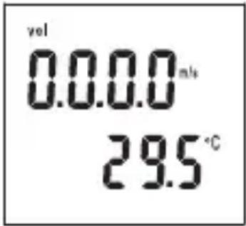
View the air velocity and temperature readings on the LCD Display. The upper display shows the air velocity reading. The lower display shows the temperature.
Air Flow Measurements
In order to take air flow measurements, the area of the duct under test (in ft2 or m2) must first be determined (check with the duct manufacturer if necessary). Once the area is known, enter the value as follows:
- Turn on the meter with the ON/OFF button.
- Press and hold the MODE button until a beep is heard. "AREA" appears on the display and one digit will be blinking indicating that value can be changed.
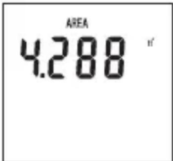
- Press the HOLD button to adjust the digit to the value needed.
- Press the AVERAGE button to select the next digit for editing.
- When the area is correctly entered, press the MIN MAX button once. A beep will sound and the digits will stop blinking.
- Press the HOLD button once to store the area value.
- The meter is now ready to measure air flow. Place the sensor in the air current and view the air flow and temperature readings on the LCD.
Single Point MIN/MAX/AVG Recording
This meter can record and display the lowest (MIN), highest (MAX), and average (AVG) air velocity, air flow, and temperature readings.
- Follow the instructions for starting air velocity or air flow measurements detailed on the previous page.
- Press the MIN MAX button. The REC and AVG (average) indicators will appear on the display and the meter will begin recording data.
-
When the measurement session is complete (up to 2 hours maximum), press the HOLD button until the beep sounds.
-
To view the MIN reading, press the MIN MAX button twice or until the MIN indicator appears. The minimum reading will be displayed on the LCD.
-
Press MIN MAX again to view the maximum value, the MAX indicator along with the maximum reading will appear on the LCD display.
-
Press MIN MAX again to view the averaged value, the AVG indicator along with the average reading will appear on the LCD display.
-
To exit this mode, press and hold the MIN MAX button until 2 beeps are heard in rapid succession and the display indicators (REC, MIN, MAX, AVG) disappear.
Multi Point Average Recording
The meter can take up to 8 separate measurements and average them automatically.
- Follow the instructions for starting air velocity or air flow measurements detailed on the previous page.
- When the first measurement is taken and is on the display, press and hold the HOLD button. Release the button when the tone is heard.
- The reading will hold and the 'HOLD' icon will appear above it on the LCD.
- Press and hold the MIN MAX button until a tone is heard then release it. The LCD will briefly indicate a number (1 through 8) representing the current measurement number.
- Repeat this process until up to 8 measurements have been taken.
- Pressthe AVERAGE button to display the average of all the measurements.
- To display the average air flow, press the MODE button to enter the area, then MODE again for air flow.
- To exit this mode and erase all stored readings, press and hold the AVERAGE button until 2 beeps are heard. To exit without erasing readings, press the HOLD button.
Data Hold Feature
- While taking measurements you can freeze the displayed reading by pressing and holding the HOLD button until a beep is heard.
- The 'HOLD' indicator will appear on the LCD when the display is in this mode.
- Press and hold the HOLD button until a beep is heard to exit this mode.
Changing the Units of Measure
U.S. units of measure are °F, ft/m (feet per minute), and CFM (cubic feet per minute). Metric units are: °C, m/s (meters per second), and CMS (cubic meters per second).
- Turn the meter on by pressing and holding both the ON/OFF and the AVERAGE buttons simultaneously. Release the ON/OFF button first then release the AVERAGE button. The units of measure will appear on the LCD.
- Press the HOLD button to select Metric and the AVERAGE button to select U.S.
- Press the MIN MAX button and an "S" will appear on the LCD.
- Press the HOLD button to advance to the next selection.
- The baud rate for PC Interface models will appear (1200 or 2400). Select the baud rate, if necessary, by pressing the HOLD (1200) or AVERAGE (2400) button.
- To return to normal operation, press MIN MAX again (the "S" will reappear) then press and hold the HOLD button until the beep is heard.
AUTO POWER OFF
The TMA10A Anemometer turns off automatically after 20 minutes to conserve battery power. Press the ON/OFF and HOLD buttons to disable the Auto Power Off feature.
ERROR MESSAGE DISPLAY
If the sensor is not connected to the meter or if the sensor is inoperable, the meter beeps, the error message "E6" appears on the display, and the meter shuts down. Connect the sensor or return the meter and sensor for repair.
USEFUL EQUATIONS AND CONVERSIONS
Cubic Equations
CFM (ft3/min) = Air Velocity (ft/min) x Area (ft2)
CMS (m3/sec) = Air Velocity (m/sec) x Area (m2)
Units Conversion Table
| m/s ft/min knots km/h MPH | |||||
| 1 m/s 1 196.87 1.944 3.6 2.24 | |||||
| 1 ft/min 0.00508 1 0.00 987 0.01829 0.01138 | |||||
| 1 knot 0.5 144 101.27 1 1.8519 1.1523 | |||||
| 1 km/h 0.2 778 54.69 0.54 1 0.6222 | |||||
| 1 MPH 0.4 464 87.89 0.8679 1.6071 1 | |||||
REPLACING THE BATTERY
Replace the 9 V battery when the display is flashing or there is no display.
- Remove the Phillips head screw on the battery compartment cover.
- Lift off the rear battery compartment cover.
- Replace the 9 V battery and secure the battery compartment cover.
SPECIFICATIONS
| Display Dual 4-digit (9999 count) LCD | |
| Measurement units | Air Velocity: ft/min (feet per minute); m/s (meters per second) Air Flow: CMS (m3/sec) and CFM (ft3/min); Temp: °C and °F |
| Data hold Freezes displayed reading | |
| Sensors | Air velocity/flow sensor: Conventional angled vane arms with low-friction ball bearing. Temp. sensor: Precision thermistor |
| MIN MAX Memory | Record and view minimum and maximum readings |
| Average reading memory | Single Point (up to 2 hours) or Multi-Point (up to 8 readings) |
| Automatic Power off | Sleep mode (with bypass) after 20 mins. conserves energy |
| Operating Temperature 32 | °F to 122 °F (0°C to 50 °C) |
| Operating Humidity Max. | 80% RH |
| Power Supply | 9 V battery (Heavy duty alkaline); Battery life: 100 hours |
| Weight 0.8 lb (363 g) including battery and sensor | |
| Dimensions | Main instrument: 7.1 x 2.8 x 1.4 in (181 x 71 x 38 mm) Sensor head diameter: 70 mm |
| Air Velocity Measurements | Range Resolution Accuracy | ||
| m/s (meters per sec) | 0.40 to 25.00 m/s 0.01 m/s ±2% of full scale | ||
| ft/min (feet per minute) | 125 to 4900 ft/min 1 ft/min ±2% of full scale | ||
| Air Flow Measurements | Range Resolution Area | ||
| CMS (cubic meters per sec.) | 0.01 to 99.99 m3/sec | 0.01 to 9.999 m 2 | |
| CFM (cubic feet per minute) | 1 to 9999 ft3/min | 1.0 | 0 to 9.999 ft2 |
| Air Temperature | Range Resolution Accuracy | ||
| 32 to 122 °F(0 to 50 °C) | 0.1 °F/°C | ±1.5 °F (0.8 °C) | |
TMA10A Anémomètre
Mode d'emploi
6/2018, 6011186 Rev B
©2018 Amprobe
EQUATIONS ET CONVERSIONS UTILES 7
Equations cubiques.... 7
REPLACEMENT DE LA PILE....7
CARACTÉRISTIQUES 8
EQUATIONS ET CONVERSIONS UTILES
Equations cubiques
CFM (pieds 3 /mn) = Vitesse de l'air (pieds/mn) x section (pieds 2 )
CMS (m 3 /s) = Vitesse de l'air (m/s) x section (m 2 )
vel FLOW AREA Hold knots
8.8.8.8 ft/m ft m/s m m l/h cfm km/h cms
MIN REC -1.8.8.8°C MAX AVG °F
USO DEI PULSANTI....2
INDICATORI DEL DISPLAY ....3
Visit amprobe.com for
- Catalog
- Application notes
• Product specifications - User manuals
Amprobe®
amprobe.com Division of Fluke Corp.
6920 Seaway Blvd.
M/S 143F
Everett, WA 98203 USA
Tel: 877-AMPROBE (267-7623)
Beha-Amprobe®
beha-amprobe.com
c/o Fluke Europe BV
Science Park
Eindhoven 5110
NL-5692 EC Son
Tel.: +49 (0) 7684 8009 - 0
- LIMITED WARRANTY AND LIMITATION OF LIABILITY
- REPAIR
- IN-WARRANTY REPAIRS AND REPLACEMENT – ALL COUNTRIES
- NON-WARRANTY REPAIRS AND REPLACEMENT – UNITED STATES AND CANADA
- NON-WARRANTY REPAIRS AND REPLACEMENT – EUROPE
- BEHA-AMPROBE
- CONTENTS
- AIR VELOCITY MEASUREMENTS
- AIR FLOW MEASUREMENTS
- SINGLE POINT MIN/MAX/AVG RECORDING
- MULTI POINT AVERAGE RECORDING
- DATA HOLD FEATURE
- CHANGING THE UNITS OF MEASURE
- AUTO POWER OFF
- ERROR MESSAGE DISPLAY
- USEFUL EQUATIONS AND CONVERSIONS
- CUBIC EQUATIONS
- UNITS CONVERSION TABLE
- REPLACING THE BATTERY
- TMA10A ANÉMOMÈTRE
- EQUATIONS ET CONVERSIONS UTILES 7
- REPLACEMENT DE LA PILE....7
- CARACTÉRISTIQUES 8
- EQUATIONS ET CONVERSIONS UTILES
- EQUATIONS CUBIQUES
- VISIT AMPROBE.COM FOR
- AMPROBE®
- BEHA-AMPROBE®
Brand : Amprobe
Model : TMA10A
Category : Anemometer