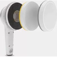
452 - Multimeter RaySafe - Free user manual and instructions
Find the device manual for free 452 RaySafe in PDF.



| Product type | Radiation protection multimeter |
| Brand | RaySafe |
| Model | 452 |
| Dimensions | 250 x 127 x 83 mm |
| Weight | 0.8 kg |
| Power supply | Built-in rechargeable lithium-ion battery, 2550 mAh, battery life up to 100 h |
| Display | Color LCD 240 x 400 pixels, backlit, readable in direct sunlight |
| Detectors | Geiger-Müller pancake counter (α, β, γ) and semiconductor sensors |
| Dose rate range (H*(10)) | 0 μSv/h to 1 Sv/h |
| Dose rate range (K_air) | 0 μGy/h to 1 Gy/h |
| Energy range (H*(10)) | 16 keV to 7 MeV |
| Energy range (K_air) | 30 keV to 7 MeV |
| Counting range (α, β, γ) | 0 cps to 20 kcps |
| Protection rating | IP64 (with cover installed, seals intact) |
| Operating temperature | -20 °C to +50 °C |
| Storage temperature | -30 °C to +70 °C |
| Connectivity | Micro USB (charging and communication), RaySafe View software |
| Data storage | 4000 stored measurements and 10 days of rate log (1 s resolution) |
| Mounting | Standard 1/2" tripod thread |
| Cleaning | Damp cloth and mild detergent, with cover installed |
| Safety | Compliant with IEC 61010-1:2010, pollution degree 2 |
| Warranty | 1 year (extendable to 2 years with calibration) |
| Repairability | No user-serviceable parts, contact manufacturer |
Frequently Asked Questions - 452 RaySafe
User questions about 452 RaySafe
0 question about this device. Answer the ones you know or ask your own.
Ask a new question about this device
Download the instructions for your Multimeter in PDF format for free! Find your manual 452 - RaySafe and take your electronic device back in hand. On this page are published all the documents necessary for the use of your device. 452 by RaySafe.
USER MANUAL 452 RaySafe
MANUEL UTILISATEUR (FR)......63
MANUALE D'USO (IT) 83
取扱説明書 (JA)....103
MANUAL DO USUÁRIO (PT_BR) 123
用户手册(ZH)....143
ID label
PN 5000195-1.00
June 2019,
© 2019 Fluke Corporation. All rights reserved. Specifications are subject to change without notice.
All product names are trademarks of their respective companies.
Users Manual (EN)
ABOUT RAYSAFE 452 4
GETTING STARTED 5
ACTIONS AND SETTINGS....6
Screen overview....6
Store measurements....6
Access stored measurements....6
Lids and quantities 7
Buttons and menus 7
MEASURE WITH LID 9
Measurement parameters....9
Intermittent radiation sources....10
MEASURE WITHOUT LID....10
Measurement parameters....11
Activity calculation.... 12
RAYSAFE VIEW 12
MAINTENANCE....13
Charge the battery 13
Cleaning....13
Storage 13
Service 13
ERRORS AND SYMBOLS 13
Instrument errors.... 13
Other display symbols....14
Symbols on labels 14
TECHNICAL SPECIFICATIONS....15
General 15
Radiology....15
Sensor position.... 17
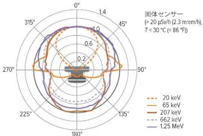
Angular response - H^*(10) 18
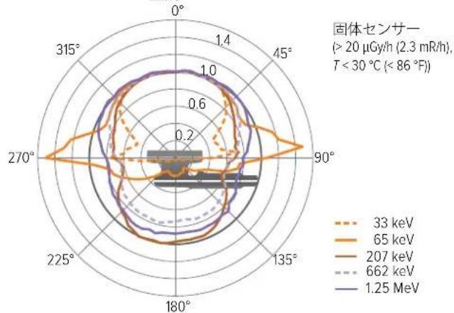
Angular response - K_air 19
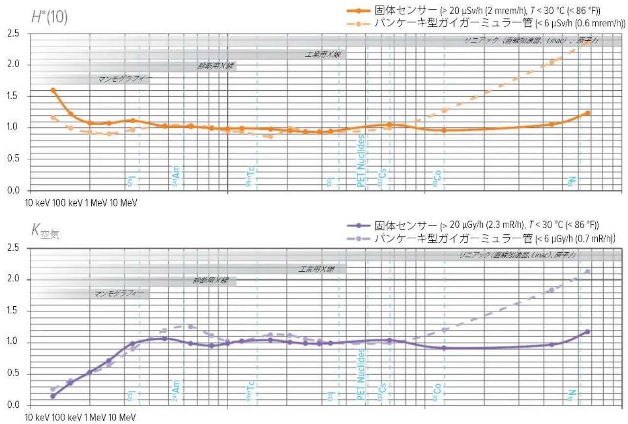
Typical energy response 20
SOFTWARE LICENSES 21
WARRANTY....21
SERVICE AND SUPPORT CONTACTS 21
ABOUT RAYSAFE 452
The RaySafe 452 is a hand-held device designed for monitoring and measuring radiation levels indoors and temporarily outdoors, in nuclear, industrial and medical applications.
⚠ WARNING The RaySafe 452 does not replace any radiation protection equipment.
⚠ WARNING The RaySafe 452 is not a replacement for personal or legal dosimeters.
⚠ WARNING The RaySafe 452 is not approved for use in environments with explosive atmosphere.
⚠ WARNING Use RaySafe 452 only as specified or the protection provided in the design may be compromised.
⚠ WARNING Take special care when measuring on intermittent radiation sources, such as pulsed X-rays or linear particle accelerators (linacs). See "Intermittent radiation sources" on page 10.
The RaySafe 452 (the instrument) is used with different lids, or without lid, to quantify dose, dose rate, mean photon energy, counts and count rate.
The instrument consists of two automatically handled sensor systems:
- A Geiger-Müller pancake, used at low dose rates and, without lid, as an // (alpha, beta, gamma) counter.
- A cluster of solid-state sensors, used at medium to high dose rates.
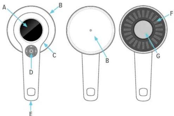
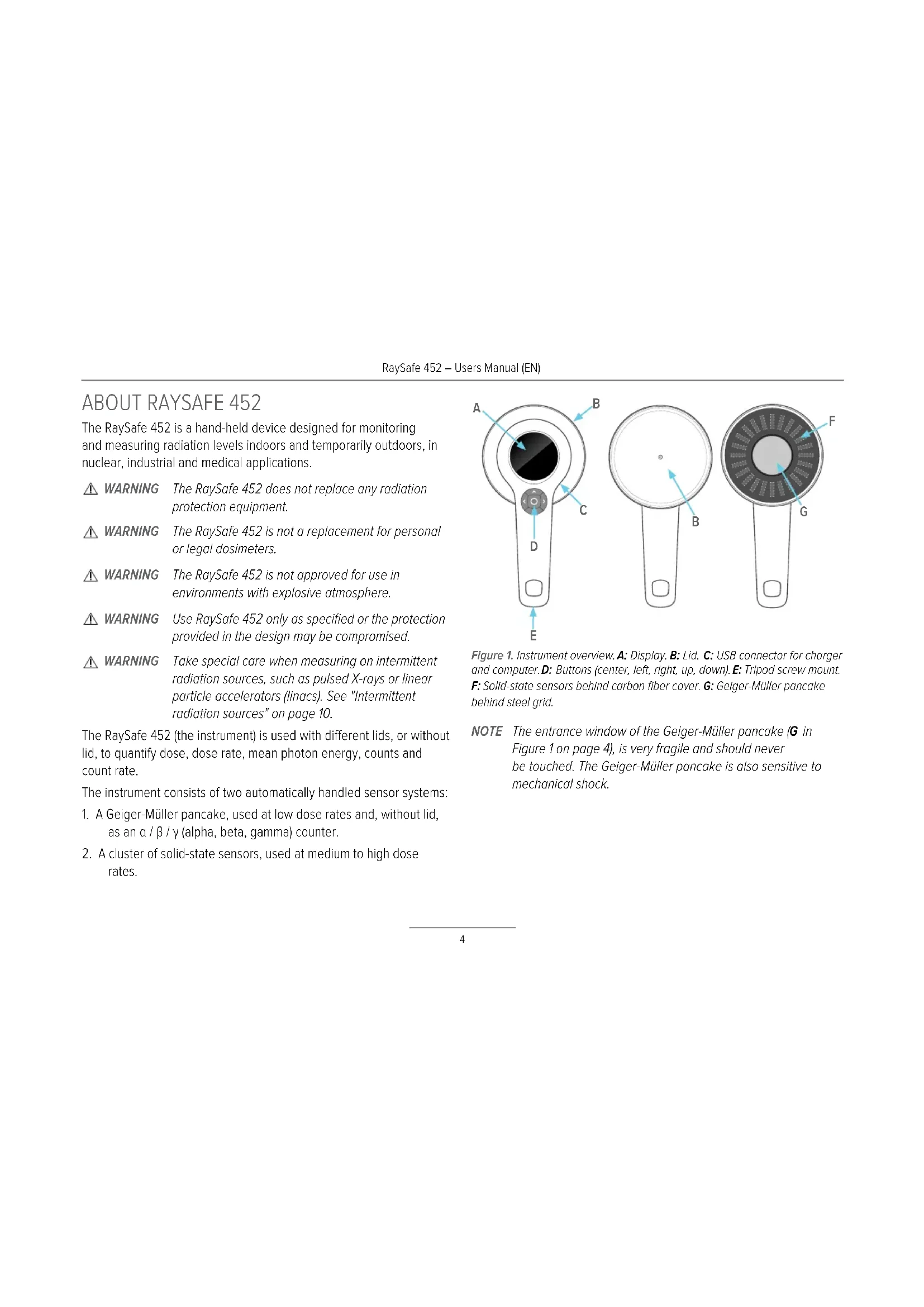
Figure 1. Instrument overview. A: Display. B: Lid. C: USB connector for charger and computer. D: Buttons (center, left, right, up, down). E: Tripod screw mount. F: Solid-state sensors behind carbon fiber cover. G: Geiger-Müller pancake behind steel grid.
NOTE The entrance window of the Geiger-Müller pancake (G in Figure 1 on page 4), is very fragile and should never be touched. The Geiger-Müller pancake is also sensitive to mechanical shock.
GETTING STARTED
Power on the instrument with a long press (approximately 3 seconds) on the center button (⏻).
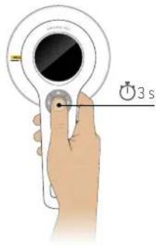
Figure 2. Power on.
The instrument starts to measure after about 5 seconds.
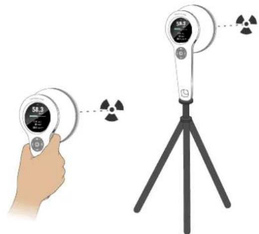
Position the instrument with the sensors towards the radiation source. The instrument will switch between its different sensor systems and adapt its averaging times automatically.
Measurement quantities change with the lid. See "Lids and quantities" on page 7.
natural_image
Illustration of a hand holding a digital display device next to a tripod-mounted device with radiation symbols (no text or labels)Figure 3. Position with the sensor area facing the radiation source.
Power off with a long press on the center button. The instrument automatically stores a log of rate values with 1 second resolution.
ACTIONS AND SETTINGS
Screen overview
gauge
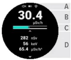
| Value | Label | |---|---| | 30.4 | μSv/h | | 282 | nSv | | 56 | keV | | 65.4 | μSv/h^ | | A | | | B | | | C | | | D | |Figure 4. Screen overview.
A. Status symbols: measurement sound, battery and display backlight.
B. Current dose rate or count rate. The displayed quantity and unit change with lid and settings. See Table 1 on page 7 for more information.
C. Rate bar. The rate bar shows the current rate, without averaging, updated 4 times per second. The scale is logarithmic and covers the specified rate range.
D. Varying content: current measurement parameters, settings, stored measurement, error screen or confirmation screen, depending on user interaction and environmental conditions.
Store measurements
Manually store a measurement with a short press on the center button.
Storing a measurement saves and resets all displayed readings.
A measurement will also be stored automatically:
- When mounting or unmounting a lid.
- When the instrument powers off.
- When an error state interrupts the ongoing measurement.
• After 24 hours of continuous measurement.
Access stored measurements
All stored measurements can be accessed using a computer running RaySafe View. See "RaySafe View" on page 12. Recent measurements have a rate log with 1 second resolution, displayed in RaySafe View as a waveform.
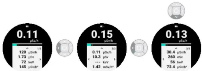
Measurements stored since last power-on can be accessed in the instrument display. Press the down arrow to view the stored measurements. See Figure 5 on page 6. Step between measurements using the left and right arrow buttons.
other
| Device | Value | |---|---| | 120 μSv/h | 0.11 | | 1.73 μSv | | | 72 keV | | | 145 μSv/h^ | | | 0.11 μSv/h | 0.15 | | 10.3 μSv | | | 1.42 mSv/h^ | | | 30.4 μSv/h | 0.13 | | 260 nSv | | | 56 keV | | | 72.4 μSv/h^ | |Figure 5. Access stored measurements.
After 10 days of logging, or 4000 stored measurements, the oldest entries will be cyclically overwritten.
Lids and quantities
Depending on model, the instrument is equipped with different sets of lids with different filter compositions.
The lids have bayonet mounts. Align the line on the lid with the line on the instrument, bring together and turn to fasten the lid.
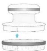
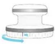
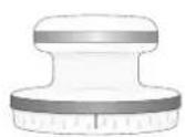
Figure 6. Mount a lid.
| LID NAME DOSE QUANTITY UNITS | ||
| Ambient Ambient dose equivalent, H*(10) Sv, rem | ||
| Air kerma | Air kerma, K_air | Gy |
| Absorbed dose to air, D_air | rad | |
| Exposure, X R | ||
| Without lid Counts (α, β, γ) cps, cpm | ||
Table 1. Lids and measured quantities.
Change the measurement unit in the settings menu. See "Buttons and menus" on page 7.
The instrument is calibrated with its associated lid(s), and shall only be used with the lid(s) provided with the instrument. Calibration date and serial number are printed on the lid label.
NOTE Before exposing the instrument to water or dust, make sure that the rubber sealing is intact and clean, that the lid is properly mounted, and that nothing is connected to the USB connector.
Buttons and menus

Figure 7. Center button.
A long press on the center button powers on or off the instrument.
When the instrument shows the measurement screen, a short press on the center button stores a measurement. At all other screens, a short press on the center button returns the measurement screen.
Figure 8. Arrow buttons.
The measurement screen is the default screen after power on. Press up from the measurement screen to access settings.
Press left or right as indicated on the screen to step between selectable settings. The setting is changed immediately. Press the center button to return to the measurement screen.
Press down from the measurement screen to access stored measurements. The stored measurements are sorted in chronological order, from right to left.
RaySafe 452 – Users Manual (EN)
There are two shortcuts:
- A long press on the left arrow button toggles the measurement sound (on/off).
- A long press on the right arrow button toggles the display backlight (on/off).
Menu structure
About
Information screen with firmware version (FW), serial number (S/N), checksum for adjustment data (CRC), and adjustment date (Adj.).
Alarm level
Select a rate alarm level: Off, Test, or a level from a selection spread over the range of the current rate quantity.
Unit
Change measurement unit. Dependent on lid status. See "Lids and quantities" on page 7.
Measurement sound
Turn on or off the measurement sound. Each pop sound corresponds to a discharge of the Geiger-Müller pancake, to a maximum frequency of 500 pops per second.
Backlight Turn on or off the display backlight.
Measurement screen
Current measurement parameters, default screen after power on.
Stored measurements
Access measurements stored since the instrument was last powered on. See "Access stored measurements" on page 6.
MEASURE WITH LID
Select which lid to use (Ambient or Air kerma).
-
Mount the lid.
-
Position the instrument with the sensors (the flat area of the lid) facing the radiation source.
The instrument handles its two sensor systems seamlessly, for both continuous sources of radiation, and for intermittent sources. See "Intermittent radiation sources" on page 10.
The instrument has no zero adjust functionality, and measurements include background radiation.
Measurement parameters
Dose and dose rate
Dose is all dose accumulated during the current measurement.
Dose rate uses an algorithm that detects radiation changes with a response time of a few seconds or less, but may in some cases need more time to stabilize, according to Table 2 on page 9.
| DOSE RATE(μGy/h, μSv/h) | DOSE RATE(mrad/h, mR/h, mrem/h) | TIME TO MAXSTABILITY |
| ≤0.1 ≤ 0.01 60 s | ||
| 0.3 0.03 30 s | ||
| 1 0.1 10 s | ||
| 3 0.3 10 s | ||
| 10 1 10 s | ||
| 30 3 10 s | ||
| 100 10 5 s | ||
| ≥300 ≥ 30 2 s |
Table 2. Dose rate stabilization times.
NOTE Dose rate readings may need additional time to stabilize on a lower value after high radiation levels, due to afterglow of scintillators in the solid-state sensors.
NOTE The instrument is not sensitive to neutrons. This has been tested using thermal neutrons from a moderated ^241 Am-Be source. The response was found to be less than 5 % of the neutron ambient dose equivalent.
Peak dose rate
Peak dose rate is the highest displayed dose rate reading since last reset. See definition of dose rate.
NOTE The instrument detects muons, created when interstellar high energy particles from the Milky Way crashes into the Earth's atmosphere. The muons interact with the solid-state sensors (when measuring with lid) and create short (1–2 s) dose rate pulses of approximately 100 times background. At sea level,
the instrument typically detects a few muons per day, but at higher altitudes, for example when travelling by air, the number increases to hundreds per day.
Mean photon energy
Mean photon energy uses a moving average of up to 10 seconds. The averaging time is shortened whenever a change in dose rate is detected.
Intermittent radiation sources
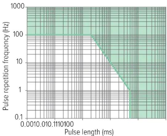
Dose is accurate for short pulse lengths due to the fast dead time corrections and sensor algorithms. See Figure 9 on page 10.
line
| Pulse length (ms) | Pulse repetition frequency (Hz) | | ----------------- | -------------------------------- | | 0.001 | 100 | | 0.01 | 10 | | 0.1 | 1 | | 1 | 0.1 | | 10 | 0.1 | | 100 | 0.1 |Figure 9. Performance on intermittent radiation, for temperatures up to 30 °C (86 °F). Green area: Response within ±20 % of the response at continuous radiation.
Dose rate is averaged over 1 second or longer, and updated once per second. Therefore, the instrument needs a radiation pulse of at least 2 seconds to reliably measure the rate of the pulse. It is possible to manually calculate the rate of a shorter pulse using the measured dose and a known pulse length.
When measuring on continuously repeating pulses, for example from pulsed fluoroscopy or linacs, the instrument measures average dose rate. If the duty cycle is known, it can be used as a correction for calculating the radiation rate in the pulses.
NOTE At temperatures above 30 °C (86 °F) the instrument's ability to handle radiation from intermittent sources gradually declines with increasing temperature.
MEASURE WITHOUT LID
When measuring without lid, for example on a potentially contaminated surface:
- Unmount the lid. When measuring without lid, the active sensor is the Geiger-Müller pancake, G in Figure 1 on page 4.
- Turn on the measurement sound.
Tip: Long press on the left arrow button toggles the measurement sound on or off. - Hold the instrument close to, but not in contact with, the surface.
- Scan the surface slowly, approximately 1 cm/s ( 12 inch per second).
RaySafe 452 – Users Manual (EN)
The instrument counts discharge avalanches in the Geiger-Müller pancake, caused by alpha, beta and gamma radiation. After each discharge, the pancake takes some tens of microseconds to recharge, called the dead time. The instrument corrects for the effect of this dead time each millisecond, automatically.
The instrument has no zero adjust functionality, and measurements include background radiation.
Measurement parameters
Counts
Counts is the sum of all discharge events during the current measurement, corrected for dead time every millisecond.
Count rate
Count rate uses an algorithm that detects changes in radiation with a response time of a few seconds or less, but may in some cases need more time to stabilize. See Table 3 on page 11.
Count rate is averaged over 1 second or longer, and updated once per second, why the instrument needs a stable radiation level for at least 2 seconds to reliably measure the rate.
| RATE (cps) | RATE (cpm) | TIME TO MAX STABILITY |
| ≤0.5 ≤ 30 60 s | ||
| 1.5 90 33 s | ||
| 5 300 10 s | ||
| 15 900 10 s | ||
| 50 3 k 10 s | ||
| 150 9 k 7 s | ||
| 500 30 k 4 s | ||
| ≥1500 ≥ 90 k 2 s |
Table 3. Count rate stabilization times.
Peak count rate
Peak count rate is the highest displayed count rate since last reset.
See definition of count rate.
Activity calculation
The approximate activity of detected nuclides can be calculated from count rate, see Table 4 on page 12. For non-listed nuclides, interpolate using the decay type and particle energy.
| RADIONUCLIDE | DECAY (E_max , MeV) | TYPICAL ACTIVITYPER COUNT RATE(Bq/cps), (dpm/cpm) |
| ^14C | ^- (0.16) 17 | |
| ^80Co | ^- (0.32) 6 | |
| ^36Cl | ^- (0.71) 4 | |
| ^90Sr / ^90Y | ^- (0.55 / 2.28) 3 | |
| ^233Pu a (5.16) 8 | ||
| ^741Am a (5.49) 8 |
Table 4. Conversion factors from count rate to activity.
Table 4 on page 12 is based on measurements made with 3 mm distance between the instrument housing (without lid) and an Al plate with a thin layer of radionuclide (wide area class 2 source according to ISO 8769:2010). Under other measurement conditions, for example different physical properties of the sample, such as thickness, size and purity, these conversion factors may underestimate the activity.
Example: The instrument reads 20 cps (1200 cpm) above background at a short distance from an Americium-241 containing particle. The activity of the particle is at least 20 cps × 8 Bq/cps = 160 Bq (1200 cpm × 8 dpm/cpm = 9600 dpm).
RAYSAFE VIEW
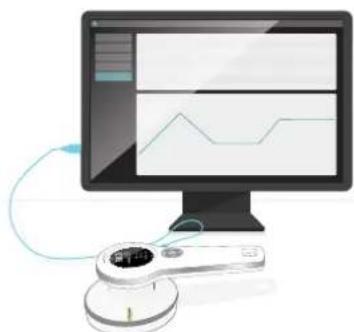
natural_image
Illustration of a computer monitor displaying a line chart on screen, connected to a handheld device (no text or symbols visible)Figure 10. Connect instrument to RaySafe View.
Use the USB cable provided with the instrument to connect to a computer running RaySafe View.
RaySafe View includes:
• Real-time display of readings.
- Remote control of the instrument (change settings, store measurements).
- Import of measurements stored in the instrument.
• Data analysis of rate log in waveform.
- Possibility to save measurements on the computer.
• Data export to Microsoft Excel and to csv files.
Download RaySafe View from www.flukebiomedical.com.
MAINTENANCE
Charge the battery
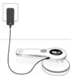
natural_image
Simple line drawing of a device with a plug and cable, no text or symbols presentFigure 11. Connect the USB charger.
To charge the battery, connect the instrument's USB connector to an indoor wall socket with the supplied charger. You can also charge with a USB power bank, or by connecting to a USB port on a computer, but charging is faster with the supplied charger (approximately 3 hours from empty to full battery).
NOTE If using the instrument while the battery symbol is red, the instrument may automatically power off at any time.

WARNING
Make sure that the USB connector on the instrument is clean and dry before connecting a cable.
Cleaning
Clean the instrument with lid mounted using a damp cloth and mild detergent.
The instrument is not water resistant with the lid off. If the instrument is contaminated with the lid off, gently wipe the contaminated area with a cloth and make sure that the instrument and lid are dry before mounting the lid.
Storage
Store the instrument powered off and with a lid mounted.
Service
Contact the manufacturer for service. See "Service and support contacts" on page 21.
NOTE RaySafe 452 has no user serviceable parts.
ERRORS AND SYMBOLS
Instrument errors
Self tests are performed at startup, and continuously during operation.
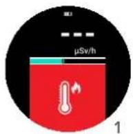
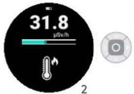
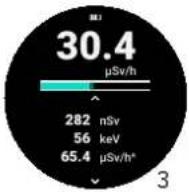
Figure 12. 1: Error screen, 2: Confirmation screen, 3: Measurement screen.
If an error occurs, the measurement screen is blocked by an error symbol on red background (1 in Figure 12 on page 13), and the instrument emits a beep every fifteenth second. While the screen is red, the instrument does not measure.
If the error ends, the instrument automatically starts a new measurement while the error symbol remains on black background (2 in Figure 12 on page 13). Press the center button to confirm the symbol and to view the ongoing measurement (3 in Figure 12 on page 13).
| ERROR SYMBOL TYPE ACTION | ||
| Instrument error (#2, #3, #4, #6, #7, #8) | Restart the Instrument. If the error remains, contact support. See "Service and support contacts" on page 21. | |
| Dose rate too high The dose rate is outside the specification.Increase the distance to the radiation source to lower the rate. | ||
| Instrument too cold Let the instrument warm up to above -20 °C (-4 °F). | ||
| Instrument too warm Let the instrument cool down to below 50 °C (122 °F). | ||
| Correct type of lid not detected | Mount a lid supplied with the instrument and/or make sure that the lid is properly mounted. Some instrument models require a lid to operate. | |
Other display symbols
| SYMBOL | TYPE MEANING | |
 | New measurement started | After 24 hours of continuous measurement, the instrument automatically stores a measurement and starts a new measurement. Confirm this with a press on the center button to return to the measurement screen. |
 | Corrupt measurement | This stored measurement is corrupt, and can not be displayed. |
Symbols on labels
| SYMBOL MEANING | |
| [108W] | Manufacturer |
| [TX20] | Article number |
 | Serial number |
| [109H] | Conforms to European Union directives. |
| [ETTW] | This product complies with the WEEE Directive marking requirements. The affixed label indicates that you must not discard this electrical/electronic product in domestic household waste. Product Category: With reference to the equipment types in the WEEE Directive Annex I, this product is classed as category 9 “Monitoring and Control Instrumentation” product. Do not dispose of this product as unsorted municipal waste. |
| [X720] | WARNING – RISK OF DANGER. Consult user documentation. |
| [TBHH] | Conforms to relevant Australian Safety and EMC standards. |
RaySafe 452 – Users Manual (EN)
| SYMBOL MEANING | |
| Conforms to the Appliance Efficiency Regulation (California Code of Regulations, Title 20, Sections 1601 through 1608), for small battery charging systems. | |
| MET Laboratories, Inc. Certification covers UL 61010-1/CSA C22.2 No. 61010-1-12. MET Laboratories, Inc. has not evaluated this device for reliability or efficacy of its intended functions. | |
| None of the China RoHS restricted substances are present above permitted levels. | |
TECHNICAL SPECIFICATIONS
General
| Safety standard Complies with IEC 61010-1:2010, pollution degree 2 |
| Radiation meter standard Complies with IEC 60846-1:2009, except EMC which complies with IEC 61326-1:2012, and except alarm sound level |
| Dimensions 250 x 127 x 83 mm (9.8 x 5.0 x 3.3 inches) |
| Weight 0.8 kg (1.7 pounds) |
| Display 240 x 400 pixel color LCD, sunlight readable, backlit |
| Rate alarm 65 cB(A) at 30 cm (12 inches) |
| Operating temperature -20 – +50 °C (-4 – +122 °F) |
| Storage temperature -30 – +70 °C (-22 – +158 °F) |
| Battery charging temperature +10 – +40 °C (+50 – +104 °F) |
| Atmospheric pressure 70 – 107 kPa, altitude up to 3000 m (10 000 ft) |
| IP code IP64 (dust proof and water resistant) according to IEC 60529:1989–2013, with lid mounted, seals intact and nothing connected to USB connector |
| Humidity, without lid < 90 % relative humidity, non-condensing |
| Battery life Up to 100 h |
| Battery Built-in rechargeable lithium-ion, 2550 mAh |
| Connector | USB micro (5 V DC, 1.3 A), for communication and charging |
| Mounting | Standard 1⁄4" tripod thread on handle |
| Data storage | 4000 stored measurements and 10 days of dose rate log with 1 s resolution |
| Software | RaySafe View (for remote control, analysis and data export) |
Radiology
Ambient dose equivalent, H*(10)
| Range | 0 μSv/h – 1 Sv/h (0 μrem/h – 100 rem/h) | |
| Rate resolution | 0.01 μSv/h (1 μrem/h) or 3 digits | |
| Dose resolution | 0.1 nSv (0.01 μrem) or 3 digits | |
| Energy range | 16 keV – 7 MeV | |
| Energy response1 | >20 μSv/h (2 mrem/h) and T < 30 °C (86 °F) | ±15 %, 20 keV – 5 MeV ±25 %, < 20 keV or >5 MeV |
| otherwise | ±20 %, 20 keV – 1 MeV -25 % – +150 %, < 20 keV or >1 MeV | |
| Minimum X-ray pulse length2 | 5 ms at T < 30 °C (86 °F) | |
| Minimum linac frequency2,3 | 100 Hz at T < 30 °C (86 °F) | |
| Rate response time | ~2 s to detect a step from 0.2 to 2 μSv/h (20 to 200 μrem/h) | |
| IEC 60846-1 energy range4 | 20 keV – 2 MeV, angle of incidence ±45° | |
| IEC 60846-1 dose rate range2 | 1 μSv/h – 1 Sv/h (100 μrem/h – 100 rem/h), non-linearity < ±10 % | |
| IEC 60846-1 dose range4 | 1 μSv – 24 Sv (100 μrem – 2.4 krem), coefficient of variation < 3 % | |
| Units | Svrem (1 rem = 1/100 Sv) | |
RaySafe 452 – Users Manual (EN)
Air kerma, K_air
| Range 0 μGy/h - 1 Gy/h (0 μR/h - 114 R/h) | ||
| Rate resolution 0.01 μGy/h (1 μR/h) or 3 digits | ||
| Dose resolution 0.1 nGy, (0.01 μR) or 3 digits | ||
| Energy range 30 keV - 7 MeV | ||
| Energy response ^1 | >20 μGy/h (2.3 mR/h) and T < 30 °C (86 °F) | ±15 %, 30 keV - 5 MeV ±25 %, 5 MeV - 7 MeV |
| otherwise ±30 %, 30 keV - 1 MeV -25 % - +120 %,1 MeV - 7 MeV | ||
| Minimum X-ray pulse length? | 5 ms at T < 30 °C (86 °F) | |
| Minimum linac frequency ^2,3 | 100 Hz at T < 30 °C (86 °F) | |
| Rate response time ~2 s to detect a step from 0.2 to 2 μGy/h (23 to 230 μR/h) | ||
| Units Gy | rad (1 rad = 1/100 Gy)R (1 R = 1/114.1 Gy) | |
Mean photon energy,
| Range 20 keV – 600 keV | |
| Uncertainty 10 % at < 100 keV, 20 % otherwise | |
| Defining standard ISO 4037-1:2019 | |
| Minimum dose rate ^5 | 20 μSv/h (2 mrem/h) or 20 μGy/h (2.3 mR/h),at T < 30^ C( 86^ F) |
Counter (α, β, γ)
| Detector type Geiger-Müller pancake | |
| Window Mica, 1.5 – 2 mg/cm | 2 |
| Sensitive area 15.55 cm | 2, behind 79 % open steel grid |
| Range 0 cps – 20 kcps (0 cpm – 1.2 Mcpm) | |
| Rate resolution | 0.1 cps (1 cpm) or 3 digits |
| Counter resolution | 1 count or 3 digits |
| Dead time correction | Automatic, linearity within -10% – +30% | ||
| Typical background at 0.1 μSv/h | 0.5 cps (30 cpm) | ||
| Typical gamma sensitivity, ^137 Cs | 6 cps / μGy/h (3000 cpm / mR/h) | ||
| Rate response time | ^42 s to detect a step from 1 to 10 cps(60 to 600 cpm) | ||
| Units | cpscpm (1 cpm = 1/60 cps) | ||
| 2π emission sensitivity ^6 | Radionuclide | Decay ( E_max ) | Typicalefficiency |
| ^14 C | β-(0.16 MeV) | 15 % | |
| ^89 Co | β-(0.32 MeV) | 31 % | |
| ^36 Cl | β-(0.71 MeV) | 43 % | |
| ^30 Sr / ^90 Y | β-(0.55 / 2.28 MeV) | 49 % | |
| ^733 Pu | α (5.16 MeV) | 26 % | |
| ^241 Am | α (5.49 MeV) | 26 % | |
FOOTNOTES
-
The instrument uses a Geiger-Muller pancake at low rates and a cluster of solid-state sensors at higher rates. The rate where the solid-state sensors are fully engaged gradually increase with temperature, for temperatures above 30 °C (86°F)
-
Limit where the response is within ±20% of the response at continuous radiation. Above 30^ ( 86^ ) the instrument's ability to handle low linear pulse rates and short X-ray pulses gradually declines with increasing temperature.
-
Refers to the microwave pulse repetition frequency of typical medical linear accelerators. Each pulse has a typical duration of a few s.
-
Ranges where the instrument fulfills IEC 60846-1:2009.
-
Above 30 °C (86 °F) the minimum dose rate gradually increases with increasing temperature.
-
Measured at 3 mm distance between instrument housing (without lid) and wide area class 2 sources according to ISO 8769.2010.
Sensor position
natural_image
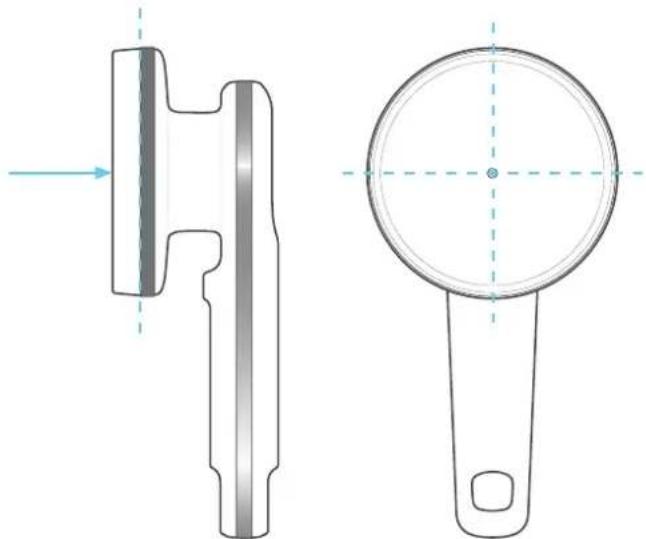
Technical line drawing of a mechanical component with cross-sectional and top views (no text or symbols)Figure 13. Sensor reference direction, reference plane and reference point.
RaySafe 452 – Users Manual (EN)
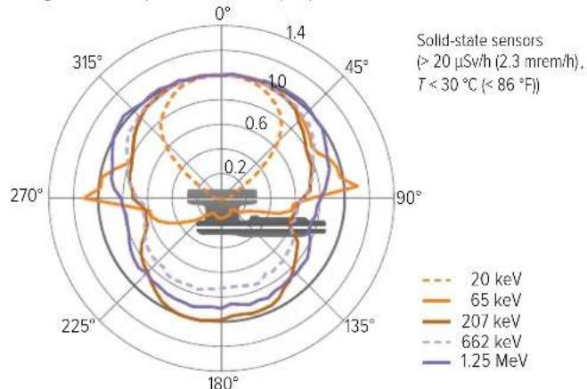
Angular response - H*(10)
radar
| Angle | 20 keV | 65 keV | 207 keV | 662 keV | 1.25 MeV | |-------|--------|--------|---------|---------|----------| | 0° | ~0.8 | ~0.9 | ~0.9 | ~0.9 | ~0.9 | | 45° | ~0.7 | ~0.8 | ~0.8 | ~0.8 | ~0.8 | | 90° | ~0.6 | ~0.7 | ~0.7 | ~0.7 | ~0.7 | | 135° | ~0.5 | ~0.6 | ~0.6 | ~0.6 | ~0.6 | | 180° | ~0.4 | ~0.5 | ~0.5 | ~0.5 | ~0.5 | | 225° | ~0.3 | ~0.4 | ~0.4 | ~0.4 | ~0.4 | | 270° | ~0.2 | ~0.3 | ~0.3 | ~0.3 | ~0.3 | | 315° | ~0.1 | ~0.2 | ~0.2 | ~0.2 | ~0.2 |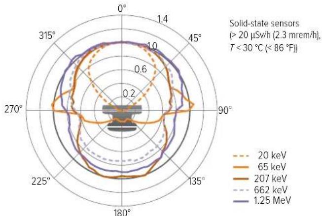
radar
| Angle | 20 keV | 65 keV | 207 keV | 662 keV | 1.25 MeV | |-------|--------|--------|---------|---------|----------| | 0° | ~0.8 | ~0.9 | ~0.9 | ~0.9 | ~0.9 | | 45° | ~0.7 | ~0.8 | ~0.8 | ~0.8 | ~0.8 | | 90° | ~0.6 | ~0.7 | ~0.7 | ~0.7 | ~0.7 | | 135° | ~0.5 | ~0.6 | ~0.6 | ~0.6 | ~0.6 | | 180° | ~0.4 | ~0.5 | ~0.5 | ~0.5 | ~0.5 | | 225° | ~0.3 | ~0.4 | ~0.4 | ~0.4 | ~0.4 | | 270° | ~0.2 | ~0.3 | ~0.3 | ~0.3 | ~0.3 | | 315° | ~0.1 | ~0.2 | ~0.2 | ~0.2 | ~0.2 |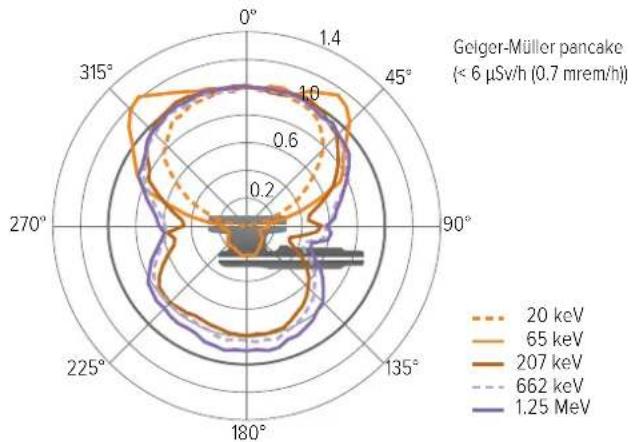
radar
| Angle | 20 keV | 65 keV | 207 keV | 662 keV | 1.25 MeV | |-------|--------|--------|---------|---------|----------| | 0° | 1.0 | 1.0 | 1.0 | 1.0 | 1.0 | | 45° | 0.8 | 0.9 | 0.9 | 0.9 | 0.9 | | 90° | 0.6 | 0.7 | 0.7 | 0.7 | 0.7 | | 135° | 0.4 | 0.5 | 0.5 | 0.5 | 0.5 | | 180° | 0.2 | 0.3 | 0.3 | 0.3 | 0.3 | | 225° | 0.4 | 0.5 | 0.5 | 0.5 | 0.5 | | 270° | 0.6 | 0.7 | 0.7 | 0.7 | 0.7 | | 315° | 0.8 | 0.9 | 0.9 | 0.9 | 0.9 |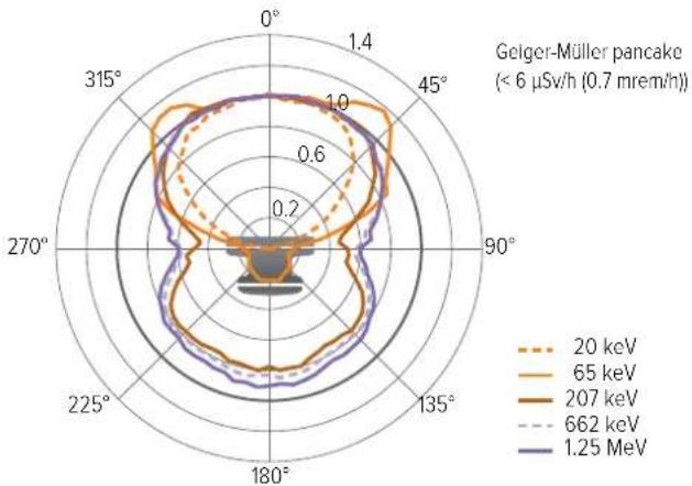
radar
| Angle | 20 keV | 65 keV | 207 keV | 662 keV | 1.25 MeV | |-------|--------|--------|---------|---------|----------| | 0° | 1.0 | 1.0 | 1.0 | 1.0 | 1.0 | | 45° | 0.8 | 0.9 | 0.9 | 0.9 | 0.9 | | 90° | 0.6 | 0.7 | 0.7 | 0.7 | 0.7 | | 135° | 0.4 | 0.5 | 0.5 | 0.5 | 0.5 | | 180° | 0.2 | 0.3 | 0.3 | 0.3 | 0.3 | | 225° | 0.4 | 0.5 | 0.5 | 0.5 | 0.5 | | 270° | 0.6 | 0.7 | 0.7 | 0.7 | 0.7 | | 315° | 0.8 | 0.9 | 0.9 | 0.9 | 0.9 |RaySafe 452 – Users Manual (EN)
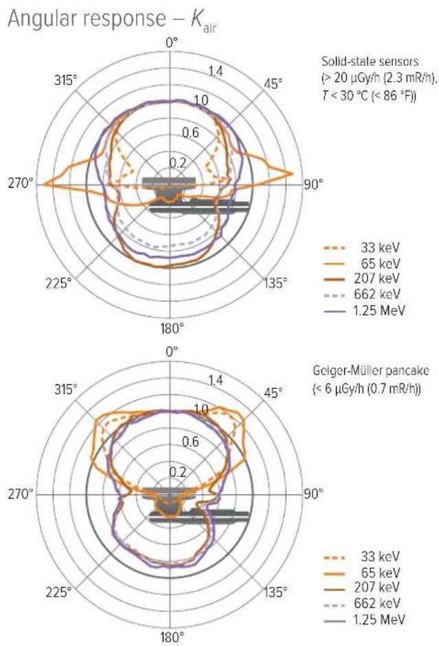

radar
| Sensor Type | Energy Level | Angle (°) | Value | | --- | --- | --- | --- | | Solid-state sensors (>20 µGy/h, T < 30 °C, < 86 °F) | 33 keV | 0° | ~0.8 | | Solid-state sensors (>20 µGy/h, T < 30 °C, < 86 °F) | 33 keV | 45° | ~0.9 | | Solid-state sensors (>20 µGy/h, T < 30 °C, < 86 °F) | 33 keV | 90° | ~0.7 | | Solid-state sensors (>20 µGy/h, T < 30 °C, < 86 °F) | 65 keV | 0° | ~0.6 | | Solid-state sensors (>20 µGy/h, T < 30 °C, < 86 °F) | 65 keV | 45° | ~0.8 | | Solid-state sensors (>20 µGy/h, T < 30 °C, < 86 °F) | 65 keV | 90° | ~0.6 | | Solid-state sensors (>20 µGy/h, T < 30 °C, < 86 °F) | 207 keV | 0° | ~0.4 | | Solid-state sensors (>20 µGy/h, T < 30 °C, < 86 °F) | 207 keV | 45° | ~0.5 | | Solid-state sensors (>20 µGy/h, T < 30 °C, < 86 °F) | 207 keV | 90° | ~0.4 | | Solid-state sensors (>20 µGy/h, T < 30 °C, < 86 °F) | 662 keV | 0° | ~0.3 | | Solid-state sensors (>20 µGy/h, T < 30 °C, < 86 °F) | 662 keV | 45° | ~0.4 | | Solid-state sensors (>20 µGy/h, T < 30 °C, < 86 °F) | 662 keV | 90° | ~0.3 | | Solid-state sensors (>20 µGy/h, T < 30 °C, < 86 °F) | 1.25 MeV | 0° | ~0.7 | | Solid-state sensors (>20 µGy/h, T < 30 °C, < 86 °F) | 1.25 MeV | 45° | ~0.5 | | Solid-state sensors (>20 µGy/h, T < 30 °C, < 86 °F) | 1.25 MeV | 90° | ~0.4 | | Solid-state sensors (>20 µGy/h, T < 30 °C, < 86 °F) | 1.25 MeV | 135° | ~0.3 | | Solid-state sensors (>20 µGy/h, T < 30 °C, < 86 °F) | 1.25 MeV | 180° | ~0.2 | | Solid-state sensors (>20 µGy/h, T < 30 °C, < 86 °F) | 1.25 MeV | 225° | ~0.1 | | Solid-state sensors (>20 µGy/h, T < 30 °C, < 86 °F) | 1.25 MeV | 270° | ~0.1 | | Solid-state sensors (>20 µGy/h, T < 30 °C, < 86 °F) | 1.25 MeV | 315° | ~0.1 | | Gelger-Müller pancake (<6 µGy/h, T < 30 °C) | 33 keV | - | ~0.9 | | Gelger-Müller pancake (<6 µGy/h, T < 30 °C) | 65 keV | - | ~1.1 | | Gelger-Müller pancake (<6 µGy/h, T < 30 °C) | 207 keV | - | ~1.0 | | Gelger-Müller pancake (<6 µGy/h, T < 30 °C) | 662 keV | - | ~1.1 | | Gelger-Müller pancake (<6 µGy/h, T < 30 °C) | 1.25 MeV | - | ~1.2 | | Gelger-Müller pancake (<6 µGy/h, T < 30 °C) | - | - | ~1.1 | | Gelger-Müller pancake (<6 µGy/h, T < 30 °C) | - | - | ~1.1 | | Gelger-Müller pancake (<6 µGy/h, T < 30 °C) | - | - | ~1.1 | | Gelger-Müller pancake (<6 µGy/h, T < 30 °C) | - | - | ~1.1 |Typical energy response
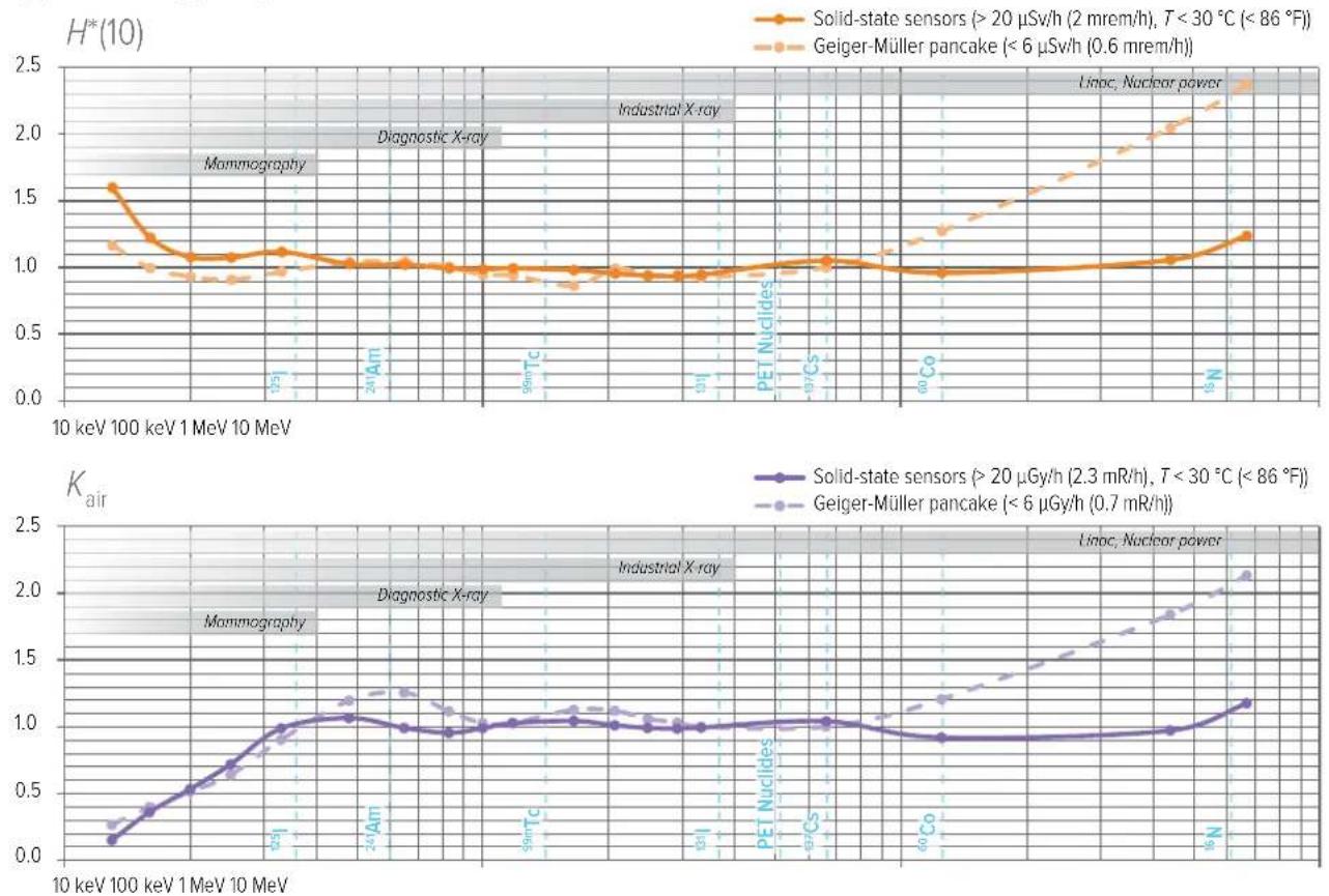
SOFTWARE LICENSES
FreeRTOS license, see the RaySafe 452 product page on www.flukebiomedical.com.
WARRANTY
Fluke Biomedical warrants this instrument against defects in materials and workmanship for one year from the date of original purchase OR two years if at the end of your first year you send the instrument to a Fluke Biomedical or RaySafe service center for calibration. You will be charged our customary fee for such calibration. During the warranty period, we will repair or at our option replace, at no charge, a product that proves to be defective, provided you return the product, shipping prepaid, to Fluke Biomedical. This warranty covers the original purchaser only and is not transferable. The warranty does not apply if the product has been damaged by accident or misuse or has been serviced or modified by anyone other than an authorized Fluke Biomedical service facility. NO OTHER WARRANTIES, SUCH AS FITNESS FOR A PARTICULAR PURPOSE, ARE EXPRESSED OR IMPLIED. FLUKE SHALL NOT BE LIABLE FOR ANY SPECIAL, INDIRECT, INCIDENTAL OR CONSEQUENTIAL DAMAGES OR LOSSES, INCLUDING LOSS OF DATA, ARISING FROM ANY CAUSE OR THEORY.
This warranty covers only serialized products and their accessory items that bear a distinct serial number tag. Recalibration of instruments is not covered under the warranty.
This warranty gives you specific legal rights and you may also have other rights that vary in different jurisdictions. Since some jurisdictions do not allow the exclusion or limitation of an implied warranty or of incidental or consequential damages, this limitation of liability may
not apply to you. If any provision of this warranty is held invalid or unenforceable by a court or other decision-maker of competent jurisdiction, such holding will not affect the validity or enforceability of any other provision.
SERVICE AND SUPPORT CONTACTS
For information about service and support, see the RaySafe 452 product page on www.flukebiomedical.com.
Manufactured by:
Fluke Biomedical
6920 Seaway Blvd.
Everett, WA
U.S.A.
RaySafe 452
other
| Parameter | Value (μSv/h) | |---|---| | Current | 120 | | Voltage | 1.73 | | keV | 72 | | Power | 145 | | Surface Brightness | 0.11 | | Surface Brightness (Current) | 0.15 | | Surface Brightness (Voltage) | 0.11 | | Surface Brightness (Current) (FeV) | 10.3 | | Surface Brightness (FeV) (FeV) | 1.42 | | Surface Brightness (FeV) (FeV) (MnV) | 30.4 | | Surface Brightness (FeV) (MnV) (MnV) | 260 | | Surface Brightness (FeV) (MnV) (MnV) | 56 | | Surface Brightness (FeV) (MnV) (MnV) | 72.4 | The chart displays three gauges: a separate one at 120 μSv/h, a higher one at 145 μSv/h, and a lower one at 120 μSv/h, all measured on a scale from 145 to 120 μSv/h.natural_image
Three-step illustration of a pushpin mechanism with a blue arrow indicating rotation (no text or symbols)natural_image
Illustration of a computer monitor displaying a line chart with a connected device (no text or symbols visible)natural_image
Simple line drawing of a device with a plug and cable, no text or symbols presentnatural_image
Technical line drawing of a mechanical component with cross-sectional and top views (no text or symbols)natural_image
Three-step diagram showing a presser's mechanism: adding a blue arrow to a flat pad, then moving a curved arrow to a circular pad (no text or symbols present)Figura 6. Monte una tapa.
natural_image
Illustration of a computer monitor displaying a line chart on screen, connected to a handheld device (no text or symbols present)Figura 10. Conecte el instrumento a RaySafe View.
natural_image
Simple line drawing of a device with a plug and cable, no text or symbols presentnatural_image
Technical line drawing of a mechanical component with cross-sectional and top views (no text or symbols)MESURE AVEC COUVERCLE 69
ERREURS ET SYMBOLES....73
natural_image
Illustration of a hand holding a digital thermometer and a tripod-mounted device with radiation warning symbols (no text or labels)natural_image
Three-step illustration of a mechanical press or knob assembly with a blue curved arrow indicating rotation (no text or symbols)MESURE AVEC COUVERCLE
natural_image
Illustration of a computer monitor displaying a line chart on screen, connected to a handheld device (no text or symbols visible)natural_image
Simple line drawing of a device with a plug and cable, no text or symbols presentnatural_image
Technical line drawing of a mechanical component with cross-sectional and top views (no text or symbols)natural_image
Three-step illustration of a pushpin mechanism with a blue arrow indicating rotation (no text or symbols)natural_image
Illustration of a computer monitor displaying a line chart on screen, connected to a handheld device (no text or symbols visible)natural_image
Simple line drawing of a device with a plug and cable, no text or symbols presentnatural_image
Technical line drawing of a mechanical component with cross-sectional and top views (no text or symbols)natural_image
Illustration of a hand holding a device with a stopwatch and 3 seconds mark (no text or symbols on the device itself)図2.電源オン
機器は約5秒後に測定を開始します。
natural_image
Illustration of a hand holding a digital thermometer and a tripod-mounted device with radiation symbols (no text or labels)natural_image
Three-step illustration of a pushpin mechanism with a blue arrow indicating rotation (no text or symbols)図6.ふたの取り付け
natural_image
Illustration of a computer monitor displaying a line chart on screen, connected to a handheld device (no text or symbols visible)natural_image
Simple line drawing of a device with a cable and a small circular component (no text or symbols)natural_image
Technical line drawing of a mechanical component with cross-sectional and top views (no text or symbols)(< 6 μSv/h (0.7 mrem/h))
20 keV
65 keV
— 207 keV
--- 662 keV
— 1.25 MeV
radar
| Angle | 20 keV | 65 keV | 207 keV | 662 keV | 1.25 MeV | |-------|--------|--------|---------|---------|----------| | 0° | 1.0 | 1.0 | 1.0 | 1.0 | 1.0 | | 45° | 0.9 | 0.9 | 0.9 | 0.9 | 0.9 | | 90° | 0.8 | 0.8 | 0.8 | 0.8 | 0.8 | | 135° | 0.7 | 0.7 | 0.7 | 0.7 | 0.7 | | 180° | 0.6 | 0.6 | 0.6 | 0.6 | 0.6 | | 225° | 0.5 | 0.5 | 0.5 | 0.5 | 0.5 | | 270° | 0.4 | 0.4 | 0.4 | 0.4 | 0.4 | | 315° | 0.3 | 0.3 | 0.3 | 0.3 | 0.3 |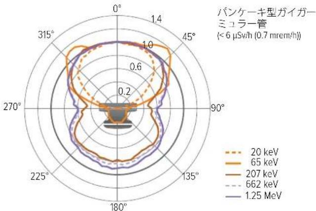
radar
| Angle | 20 keV | 65 keV | 207 keV | 662 keV | 1.25 MeV | |-------|--------|--------|---------|---------|----------| | 0° | 1.0 | 1.0 | 1.0 | 1.0 | 1.0 | | 45° | 0.8 | 0.9 | 0.9 | 0.9 | 0.9 | | 90° | 0.6 | 0.7 | 0.7 | 0.7 | 0.7 | | 135° | 0.4 | 0.5 | 0.5 | 0.5 | 0.5 | | 180° | 0.2 | 0.3 | 0.3 | 0.3 | 0.3 | | 225° | 0.4 | 0.5 | 0.5 | 0.5 | 0.5 | | 270° | 0.6 | 0.7 | 0.7 | 0.7 | 0.7 | | 315° | 0.8 | 0.9 | 0.9 | 0.9 | 0.9 |角度応答- K_空気
radar
| Angle | 33 keV | 65 keV | 207 keV | 662 keV | 1.25 MeV | |-------|--------|--------|---------|---------|----------| | 0° | ~0.8 | ~0.9 | ~0.9 | ~0.9 | ~0.9 | | 45° | ~0.7 | ~0.8 | ~0.8 | ~0.8 | ~0.8 | | 90° | ~0.6 | ~0.7 | ~0.7 | ~0.7 | ~0.7 | | 135° | ~0.5 | ~0.6 | ~0.6 | ~0.6 | ~0.6 | | 180° | ~0.4 | ~0.5 | ~0.5 | ~0.5 | ~0.5 | | 225° | ~0.3 | ~0.4 | ~0.4 | ~0.4 | ~0.4 | | 270° | ~0.2 | ~0.3 | ~0.3 | ~0.3 | ~0.3 | | 315° | ~0.1 | ~0.2 | ~0.2 | ~0.2 | ~0.2 |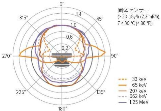
radar
| Angle | 33 keV | 65 keV | 207 keV | 662 keV | 1.25 MeV | |-------|--------|--------|---------|---------|----------| | 0° | ~0.8 | ~0.9 | ~0.7 | ~0.6 | ~0.9 | | 45° | ~0.7 | ~0.8 | ~0.6 | ~0.5 | ~0.8 | | 90° | ~0.6 | ~0.7 | ~0.5 | ~0.4 | ~0.7 | | 135° | ~0.5 | ~0.6 | ~0.4 | ~0.3 | ~0.6 | | 180° | ~0.4 | ~0.5 | ~0.3 | ~0.2 | ~0.5 | | 225° | ~0.3 | ~0.4 | ~0.2 | ~0.1 | ~0.4 | | 270° | ~0.2 | ~0.3 | ~0.1 | ~0.05 | ~0.3 | | 315° | ~0.1 | ~0.2 | ~0.05 | ~0.02 | ~0.2 |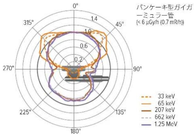
radar
| Angle | 33 keV | 65 keV | 207 keV | 662 keV | 1.25 MeV | |-------|--------|--------|---------|---------|----------| | 0° | 1.0 | 1.0 | 1.0 | 1.0 | 1.0 | | 45° | 1.0 | 1.0 | 1.0 | 1.0 | 1.0 | | 90° | 0.8 | 0.8 | 0.8 | 0.8 | 0.8 | | 135° | 0.6 | 0.6 | 0.6 | 0.6 | 0.6 | | 180° | 0.4 | 0.4 | 0.4 | 0.4 | 0.4 | | 225° | 0.2 | 0.2 | 0.2 | 0.2 | 0.2 | | 270° | 0.2 | 0.2 | 0.2 | 0.2 | 0.2 | | 315° | 0.2 | 0.2 | 0.2 | 0.2 | 0.2 |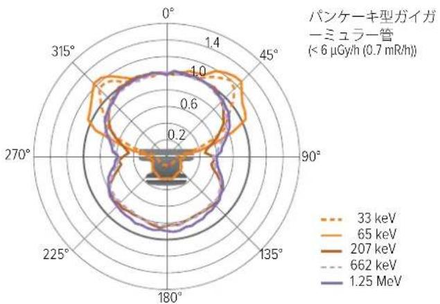
radar
| Energy (keV) | Angle (°) | Value | | ------------ | --------- | ----- | | 33 | 0 | 1.4 | | 33 | 45 | 1.4 | | 33 | 90 | 1.4 | | 33 | 135 | 1.4 | | 33 | 180 | 1.4 | | 33 | 225 | 1.4 | | 33 | 270 | 1.4 | | 33 | 315 | 1.4 | | 65 | 0 | 1.4 | | 65 | 45 | 1.4 | | 65 | 90 | 1.4 | | 65 | 135 | 1.4 | | 65 | 180 | 1.4 | | 65 | 225 | 1.4 | | 65 | 270 | 1.4 | | 65 | 315 | 1.4 | | 207 | 0 | 1.4 | | 207 | 45 | 1.4 | | 207 | 90 | 1.4 | | 207 | 135 | 1.4 | | 207 | 180 | 1.4 | | 207 | 225 | 1.4 | | 207 | 270 | 1.4 | | 207 | 315 | 1.4 | | 662 | 0 | 1.4 | | 662 | 45 | 1.4 | | 662 | 90 | 1.4 | | 662 | 135 | 1.4 | | 662 | 180 | 1.4 | | 662 | 225 | 1.4 | | 662 | 270 | 1.4 | | 662 | 315 | 1.4 | | 1.25 MeV | 0 | 1.4 | | 1.25 MeV | 45 | 1.4 | | 1.25 MeV | 90 | 1.4 | | 1.25 MeV | 135 | 1.4 | | 1.25 MeV | 180 | 1.4 | | 1.25 MeV | 225 | 1.4 | | 1.25 MeV | 270 | 1.4 | | 1.25 MeV | 315 | 1.4 |標準的なエネルギー応答
ソフトウェアライセンス
natural_image
Three-step illustration of a pushpin mechanism with a blue arrow indicating rotation (no text or symbols)natural_image
Illustration of a computer monitor displaying a line chart on screen, connected to a handheld device (no text or symbols visible)Figura 10. Conecte o instrumento ao RaySafe View.
natural_image
Simple line drawing of a device with a plug and cable, no text or symbols presentFigura 11. Ligue o carregador USB.
natural_image
Technical drawing of a mechanical component with two views: top shows a cylindrical part with a side, bottom shows a circular dial with a handle (no text or symbols)图 3. 将传感器区域对着辐射源。
gauge
| Parameter | Value (μSv/h) | | :--- | :--- | | Current | 30.4 | | Energy Level | 282 nSv | | Voltage Level | 56 keV | | Current Amplitude | 65.4 μSv/h^ | | Label | A | | Label | B | | Label | C | | Label | D |图 4. 屏幕概述。
other
| Device | Value | |---|---| | 1/3 | 0.11 | | 1/3 | 120 μSv/h | | 1/3 | 1.73 μSv | | 1/3 | 72 keV | | 1/3 | 145 μSv/h* | | 2/3 | 0.15 | | 2/3 | 0.11 μSv/h | | 2/3 | 10.3 μSv | | 2/3 | 1.42 mSv/h* | | 2/3 | 30.4 μSv/h | | 3/3 | 0.13 | | 3/3 | 260 nSv | | 3/3 | 56 keV | | 3/3 | 72.4 μSv/h* |图 5. 访问存储的测量值。
natural_image
Illustration of a computer monitor displaying a line chart on screen, connected to a remote control unit (no text or symbols present)natural_image
Simple line drawing of a device with a cable and a small circular component (no text or symbols)图 11. 连接 USB 充电器。
natural_image
Technical line drawing of a mechanical component with cross-sectional and top views (no text or symbols)
- ID label
- Users Manual (EN)
- ABOUT RAYSAFE 452
- GETTING STARTED
- ACTIONS AND SETTINGS
- Store measurements
- Access stored measurements
- Lids and quantities
- Buttons and menus
- RaySafe 452 – Users Manual (EN)
- There are two shortcuts:
- Menu structure
- MEASURE WITH LID
- Measurement parameters
- Mean photon energy
- Intermittent radiation sources
- MEASURE WITHOUT LID
- Counts
- Count rate
- Peak count rate
- Activity calculation
- MAINTENANCE
- Charge the battery
- Cleaning
- Storage
- Service
- ERRORS AND SYMBOLS
- Instrument errors
- TECHNICAL SPECIFICATIONS
- Radiology
- FOOTNOTES
- SOFTWARE LICENSES
- WARRANTY
- SERVICE AND SUPPORT CONTACTS
- MESURE AVEC COUVERCLE
- ソフトウェアライセンス
Brand : RaySafe
Model : 452
Category : Multimeter