UM24FH - Air-conditioner LG - Free user manual and instructions
Find the device manual for free UM24FH LG in PDF.
| Product Type | LG air conditioner, model UM24FH |
| Category | Air conditioner (split, cassette, wall-mounted, etc. depending on configuration) |
| Main functions | Cooling, heating, dehumidification, ventilation, automatic mode, Jet Cool, Jet Heat, sleep mode, timer, vane oscillation |
| Special functions | Air purification (Air Purify, Plasma), Auto-clean, Intelligent cleaning, Energy-saving cooling, Refresh mode, Air quality indicator |
| Remote control | Wireless with LCD display, AAA batteries (not included) |
| Power supply | Single-phase, 220-240 V, 50 Hz (check label) |
| Refrigerant | R32 or R410A (flammable) |
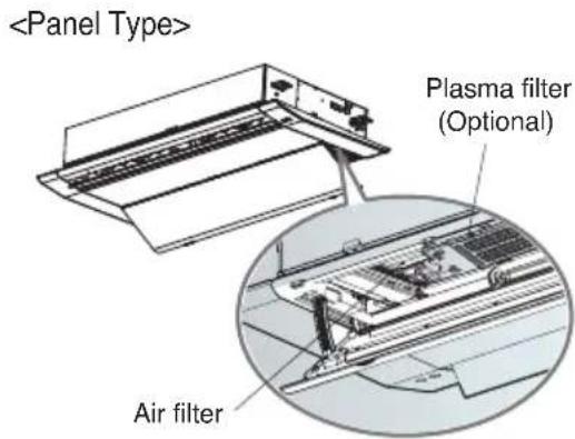
| Filters | Air filter, plasma filter (optional), deodorizing filter, PM1.0 filter (optional) |
| Filter maintenance | Clean air filter every 2 weeks, plasma filter every 3 months, deodorizing filter every 6 months |
| Safety | Automatic shutdown in case of malfunction, auto restart after power failure, gas leak protection, child lock (lock mode) |
| Installation | Must be carried out by a certified professional, in accordance with national electrical standards |
| Dimensions (indoor unit) | Variable depending on type (wall-mounted, cassette, console) – refer to installation manual |
| Weight | Variable depending on type (see installation manual) |
| Repairability | Contact an authorized LG service center; opening by a non-professional voids the warranty |
| Warranty | Manufacturer's warranty according to current conditions |
Frequently Asked Questions - UM24FH LG
User questions about UM24FH LG
0 question about this device. Answer the ones you know or ask your own.
Ask a new question about this device
Download the instructions for your Air-conditioner in PDF format for free! Find your manual UM24FH - LG and take your electronic device back in hand. On this page are published all the documents necessary for the use of your device. UM24FH by LG.
USER MANUAL UM24FH LG
Please read this manual carefully before operating your set and retain it for future reference. Installation work must be performed in accordance with the national wiring standards by authorized personnel only.
This equipment shall be provided with a supply conductor complying with the national regulation.
Original instruction (R410A/R32)
[Representative] LG Electronics Inc. Single Point of Contact (EU/UK) & EU Importer:
LG Electronics European Shared Service Center B.V.
Krijgsman 1,1186 DM Amstelveen, The Netherlands
[Manufacturer] LG Electronics Tianjin Appliances Co., Ltd.
No.09, JinWei Road, Beichen District, Tianjin, 300402.P.R.China
MFL71666509
Rev.00_011322
www.lg.com
Copyright © 2022 LG Electronics Inc. All Rights Reserved.
TABLE OF CONTENTS
3 SAFETY INSTRUCTIONS
9 Preparing for Operation
9 Usage
9 Cleaning and Maintenance
9 Service
10 OPERATING INSTRUCTIONS
10 How to insert the Batteries
10 Wireless Remote Controller Maintenance
10 Operating Method
11 Using Wireless Remote Control
12 Using the Mode Function
14 Using the Auto Operation Function
15 Using the Temperature Setting Function
16 Using the Fan Speed Function
16 Using the Air Flow Direction Function
18 Using the Optional Function
19 Using Special Functions
21 Timer Functions
22 Mode Lock setting
22 Selecting air outlet direction (for console)
25 Forced Operation
25 Auto Restart Function
26 MAINTENANCE AND SERVICE
26 Ceiling Cassette - 1Way (Grille + Panel)
27 Ceiling Cassette - 1 Way (With Air Purifier)
31 Ceiling Cassette - 4Way
34 Ceiling Cassette - Round
35 Ceiling Concealed Duct
36 Art Cool Gallery Series
38 Wall Mounted
39 Convertible
40 Console
41 When the air conditioner is not going to be used for a long time
41 Operation Tips
42 Before you call for service...
Safety Instructions
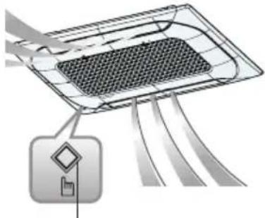
The following symbols are displayed on indoor and outdoor units.
 | Read the precautions in this manual carefully before operating the unit. |  | This appliance is filled with flammable refrigerant (for R32) |
 | This symbol indicates that the Operation Manual should be read carefully. | 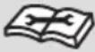 | This symbol indicates that a service personnel should be handling this equipment with reference to the Installation Manual. |
The following safety guidelines are intended to prevent unforeseen risks or damage from unsafe or incorrect operation of the appliance. The guidelines are separated into ‘WARNING’ and ‘CAUTION’ as described below.

This symbol is displayed to indicate matters and operations that can cause risk.
Read the part with this symbol carefully and follow the instructions in order to avoid risk.

WARNING
This indicates that the failure to follow the instructions can cause serious injury or death.

CAUTION
This indicates that the failure to follow the instructions can cause the minor injury or damage to the product.

WARNING
Installation
- Do not use a defective or underrated circuit breaker. Use this appliance on a dedicated circuit.
- There is risk of fire or electric shock.
-
For electrical work, contact the dealer, seller, a qualified electrician, or an Authorized Service Center.
-
Do not disassemble or repair the product. There is risk of fire or electric shock.
• Always ground the product. - There is risk of fire or electric shock.
• Install the panel and the cover of control box securely. - There is risk of fire or electric shock.
• Always install a dedicated circuit and breaker. - Improper wiring or installation may cause fire or electric shock
- Use the correctly rated breaker or fuse.
- There is risk of fire or electric shock.
- Do not modify or extend the power cable.
- There is risk of fire or electric shock.
- Do not install, remove, or re-install the unit by yourself (customer).
- There is risk of fire, electric shock, explosion, or injury.
- Be cautious when unpacking and installing the product.
- Sharp edges could cause injury. Be especially careful of the case edges and the fins on the condenser and evaporator.
- For installation, always contact the dealer or an Authorized Service Center.
- There is risk of fire, electric shock, explosion, or injury.
- Do not install the product on a defective installation stand.
- It may cause injury, accident, or damage to the product.
- Do not turn on the breaker or power under condition that front panel, cabinet, top cover, control box cover are removed or opened.
- Otherwise, it may cause fire, electric shock, explosion or death.
- Be sure the installation area does not deteriorate with age.
- If the base collapses, the air conditioner could fall with it, causing property damage, product failure, and personal injury.
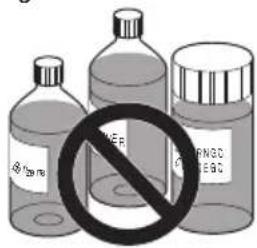
- Use a vacuum pump or Inert (nitrogen) gas when doing leakage test or air purge. Do not compress air or Oxygen and Do not use Flammable gases. Otherwise, it may cause fire or explosion.
- There is the risk of death, injury, fire or explosion.
-
The appliance shall be stored in a well-ventilated area where the room size corresponds to the room area as specified for operation. (for R32)
-
Ducts connected to an appliance shall not contain an ignition source. (for R32)
- The appliance shall be stored in a room without continuously operating ignition sources (for example: open flames, an operating gas appliance or an operating electric heater.)
- Keep any required ventilation openings clear of obstruction.
Operation
• Take care to ensure that power cable could not be pulled out or damaged during operation.
- There is risk of fire or electric shock.
- Do not place anything on the power cable.
- There is risk of fire or electric shock.
- Do not touch(operate) the product with wet hands.
- There is risk of fire or electrical shock.
- Do not place a heater or other appliances near the power cable.
- There is risk of fire and electric shock.
- Do not allow water to run into electric parts.
- It may cause There is risk of fire, failure of the product, or electric shock.
- Do not store or use flammable gas or combustibles near the product.
- There is risk of fire or failure of product.
- Do not use the product in a tightly closed space for a long time.
- Oxygen deficiency could occur.
- When flammable gas leaks, turn off the gas and open a window for ventilation before turn the product on.
- Do not use the telephone or turn switches on or off. There is risk of explosion or fire.
- If strange sounds, smell or smoke comes from product. Turn the breaker off or disconnect the power supply cable.
- There is risk of electric shock or fire.
- Stop operation and close the window in storm or hurricane.
If possible, remove the product from the window before the hurricane arrives.
- There is risk of property damage, failure of product, or electric shock.
- Do not open the inlet grill of the product during operation.
(Do not touch the electrostatic filter, if the unit is so equipped.) - There is risk of physical injury, electric shock, or product failure.
- When the product is soaked (flooded or submerged), contact an Authorized Service Center.
- There is risk of fire or electric shock.
- Be cautious that water could not enter the product.
- There is risk of fire, electric shock, or product damage.
- Ventilate the product from time to time when operating it together with a stove, etc.
- There is risk of fire or electric shock.
- Turn the main power off when cleaning or maintaining the product.
- There is risk of electric shock.
• Take care to ensure that nobody could step on or fall onto the outdoor unit.
- This could result in personal injury and product damage.
- Do not let the air conditioner run for a long time when the humidity is very high and a door or a window is left open.
- Moisture may condense and wet or damage furniture.
- Do not turn on the breaker or power under condition that front panel, cabinet, top cover, control box cover are removed or opened.
- Otherwise, it may cause fire, electric shock, explosion or death.
CAUTION
Installation
- Always check for gas (refrigerant) leakage after installation or repair of product.
- Low refrigerant levels may cause failure of product.
• Install the drain hose to ensure that water is drained away properly.
- A bad connection may cause water leakage.
- Keep level even when installing the product.
- To avoid vibration or water leakage.
- Use two or more people to lift and transport the product.
- Avoid personal injury.
- Any person who is involved with working on or breaking into a refrigerant circuit should hold a current valid certificate from an industry accredited assessment authority, which authorises their competence to handle refrigerants safely in accordance with an industry recognised assessment specification. (for R32)
- The appliance shall be stored so as to prevent mechanical damage from occurring.
- Do not install the product where the noise or hot air from the outdoor unit could damage the neighborhoods.
- It may cause a problem for your neighbors.
- If anyone other than a licensed Professional installs, repairs, or alters LG Electronics Air Conditioning Products, the warranty is voided.
- All costs associated with repair are then the full responsibility of the owner.
- Do not install the unit in potentially explosive atmospheres.
Operation
- Do not expose the skin directly to cool air for long periods of time. (Don't sit in the draft.)
- This could harm to your health.
- Do not use the product for special purposes, such as preserving foods, works of art, etc. It is a consumer air conditioner, not a precision refrigeration system.
- There is risk of damage or loss of property.
- Do not block the inlet or outlet of air flow.
- It may cause product failure.
- Use a soft cloth to clean. Do not use harsh detergents, solvents, etc.
- There is risk of fire, electric shock, or damage to the plastic parts of the product.
- Do not touch the metal parts of the product when removing the air filter. They are very sharp!
- There is risk of personal injury.
- Do not step on or put anything on the product. (outdoor units)
- There is risk of personal injury and failure of product.
- Always insert the filter securely. Clean the filter every two weeks or more often if necessary.
- A dirty filter reduces the efficiency of the air conditioner and could cause product malfunction or damage.
- Do not insert hands or other objects through the air inlet or outlet while the product is operated.
- There are sharp and moving parts that could cause personal injury.
- Do not drink the water drained from the product.
- It is not sanitary and could cause serious health issues.
- Use a firm stool or ladder when cleaning or maintaining the product.
- Be careful and avoid personal injury.
- Servicing shall only be performed as recommended by the equipment manufacturer. Maintenance and repair requiring the assistance of other skilled personnel shall be carried out under the supervision of the person competent in the use of flammable refrigerants. (for R32)
- This appliance is not intended for use by persons (including children) with reduced physical, sensory or mental capabilities or lack of experience and knowledge, unless they have been given supervision or instruction concerning use of the appliance by a person responsible for their safety.
- Children should be supervised to ensure that they do not play with the appliance.
- This appliance can be used by children aged from 8 years and above and persons with reduced physical, sensory or mental capabilities or lack of experience and knowledge if they have been given supervision or instruction concerning use of the appliance in a safe way and understand the hazards involved.
Children shall not play with the appliance. Cleaning and user maintenance shall not be made by children without supervision. - If the supply cord is damaged, it must be replaced by the manufacturer, its service agent or similarly qualified persons in order to avoid a hazard.
- Do not touch refrigerant pipe and water pipe or any internal parts while the unit is operating or immediately after operation.
- It can cause a burn or frostbite.
Prior to Operation
Preparing for Operation
- Contact an installation specialist for installation.
- Use a dedicated circuit.
Usage
- Being exposed to direct airflow for an extended period of time could be hazardous to your health. Do not expose occupants, pets, or plants to direct airflow for extended periods of time.
- Due to the possibility of oxygen deficiency, ventilate the room when used together with stoves or other heating devices.
- Do not use this air conditioner for non-specified special purposes (e.g. preserving precision devices, food, pets, plants, and art objects). Such usage could damage the items.
Cleaning and Maintenance
- Do not touch the metal parts of the unit when removing the filter. Injuries can occur when handling sharp metal edges.
- Do not use water to clean inside the air conditioner. Exposure to water can destroy the insulation, leading to possible electric shock.
- When cleaning the unit, first make sure that the power and breaker are turned off. The fan rotates at a very high speed during operation. There is a possibility of injury if the unit's power is accidentally triggered on while cleaning inner parts of the unit.
Service
For repair and maintenance, contact your authorized service dealer.
Operating Instructions
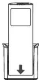
How to insert the Batteries
- Remove the battery cover by pulling it according to the arrow direction.
- Insert new batteries making sure that the (+) and (-) of battery are installed correctly.
- Reattach the cover by sliding it back into position.
NOTE
- Always use/replace both batteries of same type.
- If the system is not to be used for a long time, remove the batteries to save their working life.
- If the display screen of remote controller starts, fading replace both of the batteries.
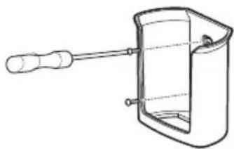
Wireless Remote Controller Maintenance
- Choose a suitable place where its safe & easy to reach.
- Fix the holder to wall etc with the supplied screws firmly.
- Slide the remote controller inside the holder.
natural_image
Line drawing of a mechanical device with a handle and internal components (no text or symbols)NOTE
- Remote controller should never be exposed to direct sunlight.
- Signal transmitter & receiver should always be clean for proper communication. Use a soft cloth to clean them.
- In case some other appliances also get operated with remote control, change their position or consult your serviceman.
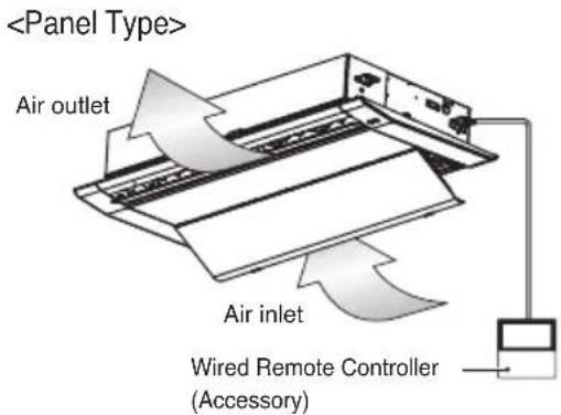
Operating Method
- The signal receiver is inside the unit.
- Aim the remote controller towards the unit to operate it. There should not be any blockage in between.
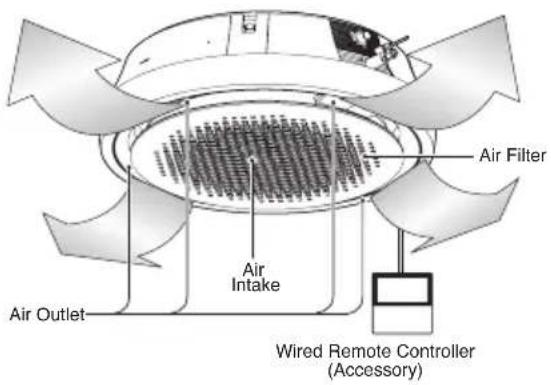
Using Wireless Remote Control
You can operate the air conditioner more conveniently with the remote control.
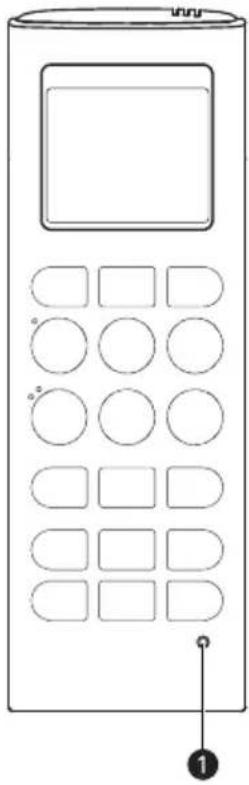
natural_image
Line drawing of a mobile phone with keypad and control panel (no text or symbols)| Button | Display Screen | Description |
| - Used | to turn on/off the unit. | |
| AIR PURIFY | Used to start or stop the air purification function. | |
| PLASMA | Used to start or stop the plasma-purification function. | |
| VANE ANGLE | Used to set each vane angle. | |
| AIR FLOW | Used to set airflow. | |
| 88° | Used to select the room temperature. | |
| MODE | - Used | to select the operation mode. |
| JET MODE | To change room temperature quickly. | |
| JET COOL | ||
| FAN SPEED | - To adjust the fan speed. | |
| FUNC. | - Used | to set or clear additional function. |
| To adjust the air flow direction vertically or horizontally. | ||
| ROOM TEMP | Used to check the room temperature. | |
| SLEEP | Used to set the time for the sleep function. | |
| ON | - Used | to set the start time. |
| OFF | - Used | to set the stop time. |
| - | Used to set the timer. Used to adjust the brightness. Used to check the room temperature. (If it is not time adjust mode) | |
| SET/CLEAR | - | Used to set/clear the timer. Used to set the current time. (hold button for 3 seconds) |
| 1 RESET | - To initialize the remote control settings. | |
NOTE
- Depending on the product type, some functions may not be available and displayed.
- Some products don't receive the wired signals.
- When using the simultaneous operation system, the system will operate approximately 1 - 2 minutes after pressing the remote controller button.
- The displayed temperature can be different from the actual room temperature if the remote controller is installed somewhere exposed to direct sunlight or is nearby a heat source.
- Depending on the product, wireless and wired remote control are optional or basic.
- Heating Mode is not available for Cooling only Models.
- Buttons may be changed according to the type of model.
Using the Mode Function
Cooling Mode
This cools the room with a comfortable and clean wind.
1 Turn the appliance on.
2 Press MODE button repeatedly to select the Cooling Mode.
- is displayed on the display screen.
3 Press or button to set the desired temperature.
4 Press FAN SPEED button repeatedly to adjust the fan speed.
NOTE
- Press the ROOM TEMP button to check the Room temperature.
- When setting the desired temperature higher than the current room temperature, the unit will produce only ventilation wind.
Dehumidification Mode
It removes humidity while slightly cooling the air.
1 Turn the appliance on.
2 Press MODE button repeatedly to select the Dehumidification Mode.
- is displayed on the display screen.
3 Press FAN SPEED button repeatedly to adjust the fan speed.
NOTE
- The temperature setting can not be adjusted when this mode is operating.
- During rainy seasons or in high-humidity climates, it is possible to simultaneously operate the dehumidifier and cooling mode to remove humidity effectively.
- The menu item of wind powerfulness might not be partially selected according to the product.
Power Cooling Mode
This cools the room with a comfortable and clean wind.
1 Turn the appliance on.
2 Press MODE button repeatedly to select the Cooling Mode.
3 Press JET MODE or JET COOL button. • Is displayed on the display screen.
NOTE
- To cancel the Power Cooling Mode, Press the JET MODE or JET COOL button, the FAN SPEED button or the ROOM TEMP button.
- This rapidly lowers the room temperature.
- Partial appliance has no Power Cooling function.
- The unit will operate at a high fan speed in cooling mode.
- The feature may be changed according to the type of model.
Heating Mode
This supplies warm wind to the inside of the building.
1 Turn the appliance on.
2 Press MODE button repeatedly to select the Heating Mode.
- is displayed on the display screen.
3 Press or button to set the desired temperature.
4 Press FAN SPEED button repeatedly to adjust the fan speed.
NOTE
- Press the ROOM TEMP button to check the Room temperature.
- When setting the desired temperature lower than the room temperature, the unit will produce only ventilation wind.
- Heating Mode is not available for Cooling only models.
- To check the indoor temperature, press the room temperature button.
Power Heating Mode
1 Turn the appliance on.
2 Press MODE button repeatedly to select the Heating Mode.
Press JET MODE button.
- Is displayed on the display screen.
NOTE
- Heating Mode is not available for Cooling only models.
- Some functions may not be supported, depending on the model.
Fan Mode
1 Turn the appliance on.
2 Press MODE button repeatedly to select the Fan Mode.
• is displayed on the display screen.
3 Press FAN SPEED button repeatedly to adjust the fan speed.
NOTE
• Natural wind based on chaos logic
- For a fresher feeling than other fan speeds, press the Indoor Fan Speed Selector and set to chaos mode. In this mode, the wind blows like a natural breeze by automatically changing fan speed based on the chaos logic.
- During Fan Mode
- The outdoor compressor doesn't work. Have a function to circulate the indoor as it sends out the air that doesn't have much temperature difference with indoor.
Using the Auto Operation Function
Auto Operation Mode
This mode automatically sets the fan speed and temperature depending on the room temperature.
Cooling Only Model
In this mode, you cannot adjust the fan speed, but you can set the air deflector to rotate automatically.
1 Turn the appliance on.
2 Press MODE button repeatedly to select the Auto Operation Mode.
• is displayed on the display screen.
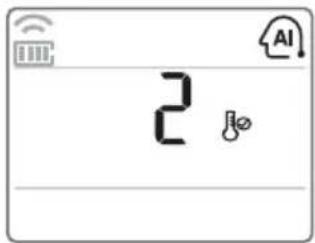
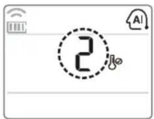
3 Press or button to set the desired temperature.
- Please select the code depend on your feeling.
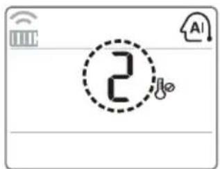
| Code Description | |
| 2 Cold | |
| 1 Slightly cool | |
| 0 Neutral | |
| -1 Slightly warm | |
| -2 Warm | |
Cooling & Heating Model
This mode changes the mode automatically to maintain the set temperature at ±2 ^ .
1 Turn the appliance on.
2 Press MODE button repeatedly to select the Auto Operation Mode.
- is displayed on the display screen.
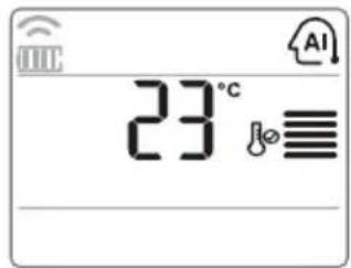
3 Press or button to set the desired temperature.
- Setting temp range: 18 °C \~ 30 °C
4 Press FAN SPEED button repeatedly to adjust the fan speed.
Auto Changeover Mode - Setting the Mode Change Temperature
Cooling & Heating Model
The Mode Change Temperature is the difference of temperature when from cooling mode to heating mode or from heating mode to cooling mode.
1 In Auto Operation Mode, Press the FUNC. button to select Setting the Mode Change Temperature.
2 Press or button to set desired Mode Change Temperautre.
- Default value is 2^ C
- Setting temp range: 1^ 7^
NOTE
When setting temperature is 25 °C and room temperature is 20 °C, then operating mode is heating. If you set the mode change temperature to 2 °C, when the room temperature up to 27 °C (25 °C + 2 °C), the unit start cooling operation.
Using the Temperature Setting Function
Temperature setting
Use this function to adjust the desired temperature.

: Increase 1^ C or 1^ F each time pressed.

: Decrease 1 °C or 1 °F each time pressed.
NOTE
- 5^ is proper for the difference between room and outside temperature.
-
Cooling operation
-
The cooling mode doesn't work if the desired temperature is higher than room temperature. Please lower the desired temperature.
- Setting temp range: 18 °C \~ 30 °C
-
Heating operation
-
The heating mode doesn't work if the desired temperature is lower than room temperature.
- Please increase the desired temperature.
-
Setting temp range: 16 °C \~ 30 °C
-
When pressing the FAN SPEED button of the remote controller for approx. 3 seconds, the room temperature will be displayed for about 5 seconds before returning to the previous display panel.
- Some functions may not be supported, depending on the model.
Switching Between Celsius/Fahrenheit
Press and hold the ROOM TEMP or FUNC. button long for 5 seconds to change from Celsius to Fahrenheit or from Fahrenheit to Celsius.
NOTE
- Some functions may not be supported, depending on the model.
Using the Fan Speed Function
Adjusting the Fan Speed
1 Turn the appliance on.
2 Press FAN SPEED button repeatedly to adjust the fan speed.
NOTE
- The menu item might not be partially selected according to product function.
- The feature may be changed according to the type of model.
Using the Air Flow Direction Function
Up/Down Airflow Direction Control (Optional)
The up/down airflow (Vertical Airflow) can be adjusted by using the remote controller.
1 Turn the appliance on.
Press SWING button.
• The louvers will swing up and down.
3 Press button again to set the vertical louver at the desired airflow direction.
NOTE
- If you press a button, the horizontal airflow direction is changed automatically based on the Auto Swing algorithm to distribute the air in the room evenly and at the same time to make the human body feel more comfortable, as if enjoying a natural breeze.
- Always use the remote controller to adjust the up/down airflow direction. Manually moving the vertical airflow direction louver by hand, could damage the air conditioner.
- When the unit is shut off, the up/down airflow direction louver will close the air outlet vent of the system.
- Some functions may not be supported, depending on the model.
Left/Right Airflow Direction Control (Optional)
The left/right (horizontal) airflow can be adjusted by using the remote control.
1 Turn the appliance on.
2 Press SWING button.
• The louvers will swing left and right.
3 Press button again to set the horizontal louver at the desired airflow direction.
NOTE
- Some functions may not be supported, depending on the model.
Indirect Wind (Optional)
It adjusts the wind direction to indirect wind.
1 Turn the appliance on.
2 Press AIR FLOW button repeatedly until icon displayed.
3 Press SET/CLEAR button to set or cancel this function.
NOTE
Some functions may not be supported, depending on the model.
Direct Wind (Optional)
It adjusts the wind direction to direct wind.
1 Turn the appliance on.
2 Press AIR FLOW button repeatedly until icon displayed.
3 Press SET/CLEAR button to set or cancel this function.
NOTE
Some functions may not be supported, depending on the model.
Smart Mode (Optional)
It is the function to set the Smart Mode operation of the product.
1 Turn the appliance on.
2 Press AIR FLOW button repeatedly until icon displayed.
3 Press SET/CLEAR button to set or cancel this function.
NOTE
- Smart Mode function can only be selected in the cooling and heating modes.
- Smart Mode / Energy Saving Cooling / Refresh Mode functions cannot be set at the same time.
- Some functions may not be supported, depending on the model.
Refresh Mode (Optional)
It is the function to set the Refresh Mode operation of the product.
1 Turn the appliance on.
2 Press AIR FLOW button repeatedly until icon displayed.
3 Press SET/CLEAR button to set or cancel this function.
4 When set, it is displayed with the animated effect in the order of
NOTE
- Refresh Mode function can only be selected in the cooling and heating modes.
- Smart Mode / Energy Saving Cooling / Refresh Mode functions cannot be set at the same time.
- Some functions may not be supported, depending on the model.
Using the Optional Function
Individual vane angle control (Optional)
This is the function that controls the vane angles individually in the ceiling cassette products.
1 Press VANE ANGLE button.
- The individual vane angle control symbol will blink.
![[]](/content/2026/03/547555/images/43b3b1dacc486bca195a53b9d5313adc440d1b0781904e5be813064158103c90.jpg)
2 Set each vane angle by pressing VANE ANGLE button.
natural_image
Pure electrical circuit lines without any symbols3 Press SET/CLEAR button to set or cancel this function.
NOTE
- There may be differences between the up/down/left/ right buttons on the wireless remote controller and the wind discharge port directions.
- Set the desired angle while checking the movement and angle of the product's vanes.
- Some functions may not be supported, depending on the model.
Air Purification / Plasma Purification (Optional)
- Press AIR PURIFY or PLASMA button.
- is displayed on the display screen.
NOTE
- If you wish to stop, press AIR PURIFY or PLASMA button again.
- When AIR PURIFY button is pressed while the unit is stopped, Air Purification will start independently.
- Plasma filter is a technology developed by LG to get rid of microscopic contaminants in the intake air by generating a plasma of highly charged electrons. This plasma kills and destroys the contaminants completely to provide clean and hygienic air.
- This function can be used in any operation mode and any fan speed can be used while the plasma filter is functioning.
- Some functions may not be supported, depending on the model.
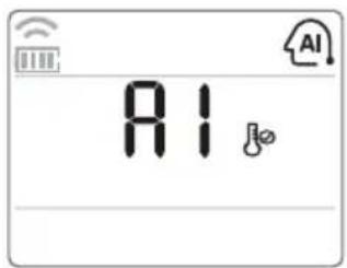
Smart Indicator (Air Quality) Always On Setting (Optional)
- Press the AIR PURIFY button for 3 seconds, Air quality level will always be displayed on Smart Indicator of the product.
NOTE
- Some functions may not be supported, depending on the model.
LCD Luminosity Control (Optional)
It is comfortable when you feel that the display of the unit too bright.
- Press the button.
Using Special Functions
Setting Special Functions
1 Press FUNC. button repeatedly to select the desired function.
2 Press SET/CLEAR button to finish.
NOTE
- Some functions may not be supported, depending on the model.
- Some functions may operate differently from the remote control display.
Canceling Special Functions
1 Press FUNC. button repeatedly to select the desired function.
2 Press SET/CLEAR button to cancel the function.
Auto Clean (Optional)
In the Cooling and Dehumidification Mode, moisture is generated inside the indoor unit. This function removes such moisture.
- is displayed on the display screen.
NOTE
- If you turn off the unit, the fan continues to run for 30 minutes and cleans the inside of the indoor unit.
- Some functions cannot be used while the Auto Clean function is in operation.
Smart Clean (Optional)
The Smart Clean function can be used by setting to manual or automatic.
- is displayed on the display screen.
Auto Smart Clean Operation
If the accumulated operation time of the product exceeds 30 hours, the Smart Clean automatically starts when the unit is turned off.
Manual Smart Clean Operation
When the unit stop, press the FUNC. button to select Smart Clean.
NOTE
- The brush clean a dust from the filter by moving from left to right or from right to left on the filter. The sucked dust is collected into the dust box.
- Some functions may not be supported, depending on the model.
Energy Saving Cooling (Optional)
Energy Saving Cooling is the function to adjust the desired temperature during cooling operation to enhance the comfort of the user and improve the energy saving performance.
• is displayed on the display screen.
NOTE
- It can be selected only during the cooling operation.
- When pressing Energy Saving Cooling while cooling at 22^ or lower, it is automatically set to 22^ .
- During the Energy Saving Cooling operation, the temperature on the remote control may be displayed differently from the air conditioner display.
- Smart Mode / Energy Saving Cooling / Refresh Mode functions cannot be set at the same time.
- Some functions may not be supported, depending on the model.
Electric Heater (Optional)
It can only be set during heating operation.
• is displayed on the display screen.
NOTE
- The indoor unit displays during the heating mode, the Auxiliary heater is automatically turned on, but it is not displayed on the wireless remote controller separately.
- It operates in Floor heating mode in Console products.
- Heating Mode is not available for Cooling only models.
- Some functions may not be supported, depending on the model.
Comfort Cooling (Optional)
This function is automatically control the cooling strength to maintain the pleasant feeling without turning off the product after the indoor temperature reached the desired temperature.
• is displayed on the display screen.
NOTE
- It can be selected only during the cooling operation.
- Some functions may not be supported, depending on the model.
Timer Functions
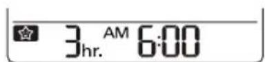
Setting the Current Time
1 Press SET/CLEAR button for 3 seconds.
2 Press or button until the desired time is set.
- If you press down and hold the button for a long time, the time will change more quickly in 10 minute increments.
NOTE
Check the indicator for A.M. and P.M.
Sleep Timer Setting
1 Turn the appliance on.
2 Press SLEEP button to turn the timer on or off.
3 Press or button until the desired time is set.
- 7 hours is the maximum setting.
4 Press SET/CLEAR button.
Setting the On Timer
1 Press ON button to turn the timer on or off.
AM 6:00 ON
2 Press or button until the desired time is set.
3 Press SET/CLEAR button.
Setting the Off Timer
1 Press OFF button to turn the timer on or off.
PM 6:00 OFF
2 Press or button until the desired time is set.
3 Press SET/CLEAR button.
Canceling the Timer Setting
You can cancel all timer settings.
- Press SET/CLEAR button.
NOTE
- If you wish to cancel a specific timer setting, press the each timer button to turn on or off the Sleep Timer, On Timer, or Off Timer as you want. Then press the SET/CLEAR button while aiming the remote controller at the signal receptor.
- The timer lamp on the air conditioner and the display will go off.
Mode Lock setting
You can select operation mode for "cooling only" or "heating only".
- Press this ▽ △ for 5 seconds or more, operation mode changed to "cooling only".
- Press this ▼ △ for 5 seconds or more, operation mode changed from “cooling only” to “heating only”.
- Press this ▽ △ for 5 seconds or more, "heating only" mode released.
- In “cooling only” or “heating only” mode, mode change cannot be choose.
NOTE
- Use other controller but wireless one, you can change operation mode.
- Some functions may not be supported, depending on the model.
Selecting air outlet direction (for console)
You can select the air outlet.
Press ON/OFF button to start the unit.
Press the AIR OUTLET button.
- If is selected, only upper air outlet will be opened and blow air.
- If is selected, only lower air outlet will be opened and blow air.
- If is selected, upper/lower air outlets will be opened and blow air.
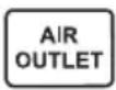
NOTE
Some functions may not be supported, depending on the model.
Checking the air quality level during air purification operation (Optional)
Press button for 3 seconds, Air quality level will always be displayed on Smart Indicator of the product.
Global
| Display Color | Air Quality Level | Concentration of dust (μg/m3) | |
| PM10 PM | 2.5/1.0 | ||
| Green Good 54 | ↓ | 12 ↓ | |
| Yellow Moderate 55-154 13-35 | |||
| Orange Unhealthy 155-254 36-55 | |||
| Red Poor 255 | ↑ | 56 ↑ | |
China/India
| Display Color | Air Quality Level | Concentration of dust (μg/m3) | |
| PM10 PM | 2.5/1.0 | ||
| Green Good | 50 ↓ | 35 ↓ | |
| Yellow Moderate | 51-150 | 36-75 | |
| Orange Unhealthy | 151-250 | 76-115 | |
| Red Poor | 251-350 | 116-150 | |
| Pink Very poor | 351 | -420 151-250 | |
| Violet Severe | 421 ↑ | 251 ↑ | |
NOTE
- The dust concentration is displayed from 8 to 999 by the unit of 1.
- The dust concentration referred to the data sheet of the sensor manufacturer.
- The dust concentration criteria for the PM1.0 dust were set based on the same criteria as the PM2.5 dust. (Company standard)
- The dust concentration and level displayed on the product may differ from other measuring instruments or other products.
- The displayed dust concentration values can differ from each other depending on the differences in dust measuring methods and also from the actual dust density.
- The dust concentration evaluation is carried out with our company's standard test dust.
- If you use a product generating steam or fine particles (humidifier, cooking appliances, sprays, etc.), the dust concentration may change.
- The dust concentration may vary depending on the installation environment and surrounding environment.
- It is also affected by sofas, beds, carpets, vacuum cleaners, humidity, smoke, bugs, pets, etc.
- It is affected by construction sites, roadsides and factories.
- Dust concentrations can be measured to be higher in an environment where external air is introduced, such as near the entrance, windows and ventilation openings.
- This is an additional function of the product and may not work in some products.
- The feature may be changed according to the type of model.
- Some functions may not be supported, depending on the model.
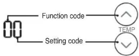
How to set Air quality level color
- With the button pressed, press the reset button.

- By using the or button, set function code and setting value.
flowchart
graph TD
    A["00"] --> B["Function code"]
    C["Setting code"] --> D["TEMP"]
    B --> D
    D --> E["✓"]
- Press the button toward the indoor unit 1 time. Each countries have different standards for indicating Overall air quality. Please refer to table below.
| Value Step Overall Air Quality. | ||
| Type1(1beep) | 4step(For Korea) | Good/Moderate/Unhealthy/Poor |
| Type2(2beep) | 4step(For Global) | Good/Moderate/Unhealthy/Poor |
| Type3(3beep) | 6step(For China) | Good/Moderate/Unhealthy/Poor/Very Poor/ Severe |
- Reset the remote controller to use the general operation mode.
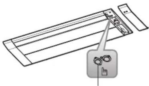
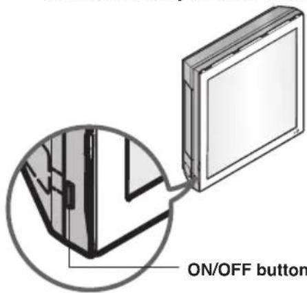
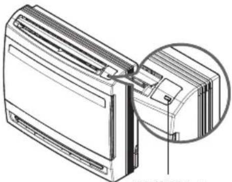
Forced Operation
Operation procedures when the remote control can't be used.
Press the tact switch (ON/OFF button) for 2 seconds.
If you want to stop operation, press again the tact switch.
In case the power comes on again after power failure on the forced operation mode, the operating conditions are automatically set as follows: During forced operation, the initial mode continues.
natural_image
Diagram of a device with a pointing cursor icon and a lock mechanism (no text or symbols)ON/OFF button
natural_image
Diagram of a device with a mesh grid and connecting cables, no text or symbols presentON/OFF button
natural_image
Technical line drawing of a front panel with a magnified inset showing internal components (no text or symbols)ON/OFF button
* The feature may be changed according to the type of model.
Auto Restart Function
In case the power comes on again after a power failure, auto restarting operation is the function to operate procedures automatically to the previous operating conditions.
Maintenance and Service
Ceiling Cassette - 1Way (Grille + Panel)
CAUTION
Before performing any maintenance, turn off the main power to the system.
■ Turn the system off before cleaning. Clean the unit with a soft dry cloth. Do not use bleach or abrasives.
NOTE
Power supply must be disconnected before cleaning the indoor unit.
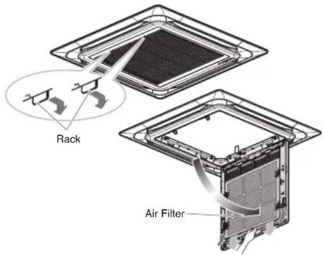
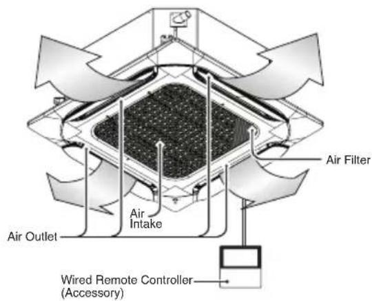
Air Filter
The air filters behind the front grille should be checked and cleaned once in every 2 weeks or more often if necessary.
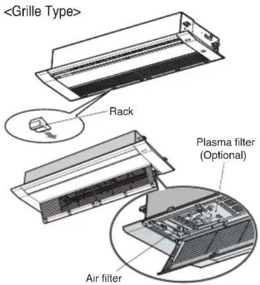
TT chassis : 6 EA Rack TU chassis : 4 EA Rack
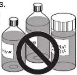
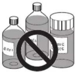
■ Never use any of the followings:
• Water hotter than 40 °C. Could cause deformation and/or discoloration.
• Volatile substances. Could damage the surfaces of the air conditioner.
- Remove air filters.
CAUTION
When the air filter is to be removed, do not touch the metal parts of the indoor unit. It may cause an injury.
- Remove Plasma filter (Optional).
■ Unscrew 2 screws from Plasma filter (Optional).
- Clean dirt from the air filter using a vacuum cleaner or washing with water.
If dirt is conspicuous, wash with a neutral detergent in lukewarm water.
■ If hot water (40 °C or more) is used, it may be deformed.
- After washing with water, dry well in the shade.
■ Do not expose the air filter to direct sunlight or heat from a fire when drying it.
- Install Plasma filter (Optional) and air filter.
Ceiling Cassette - 1 Way (With Air Purifier)
Cleaning the filter
CAUTION
Before performing any maintenance, turn off the main power to the system.
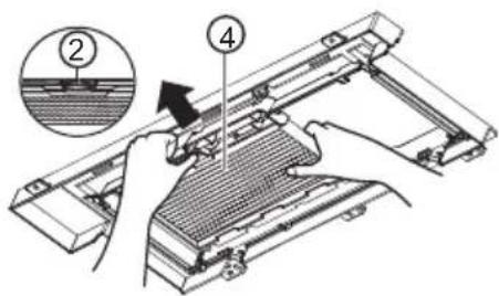
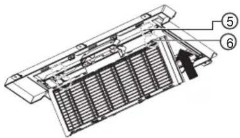
- Pull on the handles on both ends of the marked rear side of the front panel, then open the front grille and press down on the two hooks and remove the Pre-filter.
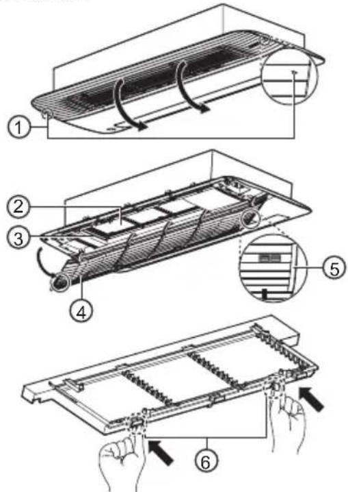
- Clean with a vacuum cleaner or a soft brush.
- If the filter is very dirty, wash using water and a neutral detergent.
-
Allow the filter to dry in the shade until completely dry.
-
Install the filter in the reverse order from which it was removed, then close the front grille.
- When installing the filter, insert the hook in the square hole.
①Marker
②Pre-filter
③Filter case
④Front intake grille
⑤Handle
⑥Hook
⑦Square hole
WARNING
For safety, turn off the main power switch.
CAUTION
- Make sure that the filter is properly installed in the filter case. (When you insert the filter into the case and push the handle, you will hear a clicking sound when it is secured in place.)
- Be careful not to drop the front grille when removing the filter.
- Do not use volatile liquids or water that is 40 °C or hotter.
- Using the filter when it is not completely dry could cause the product to malfunction.
- Drying the filter near a fire or in direct sunlight may cause damage to the filter.
- When cleaning the filter, be careful not to damage the filter's mesh.
NOTE
- If dust gets in the filter, there could be a drop in cooling capacity.
- Clean around once every two weeks.
- If you have the filter cleaned at an LG Electronics Service Center, a separate fee may be charged. (paid service)
- The number and type of filters provided may differ depending on the model.
- Product shape and components may differ depending on the model.
- The feature may be changed according to the type of model.
- Some functions may not be supported, depending on the model.
Cleaning the deodorization filter/PM1.0 filter (Optional)
-
Refer to 'How to Remove the Filter' when removing the filter.
-
Grab the handle on the filter case holder and pull in the direction of the arrow to remove the PM1.0 filter.
- Do not remove the filter case holder and the intake grille.
natural_image
Technical diagram of a mechanical component with internal ribs and directional arrows (no text or symbols)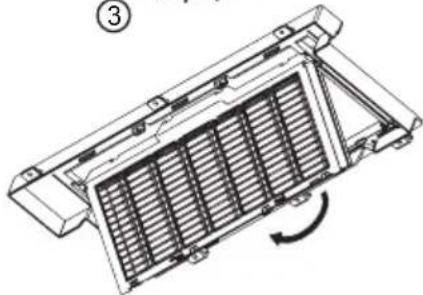
natural_image
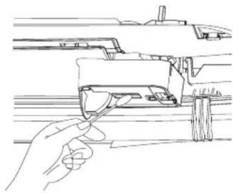
Technical line drawing of a heat exchanger or cooling unit with internal cooling fins and a rotation arrow (no text or symbols)- As shown in the figure, pull on the handle and remove the deodorization filter.

natural_image
Technical line drawing of a mechanical device with a hand operating the component (no text or symbols present)-
Wash the filter after checking the washing method in 'Filter Information'.
-
After washing, reinstall the deodorization filter and the PM1.0 filter to their original positions, respectively.
- When installing the PM1.0 filter, insert the hook in the square hole.
① PM1.0 filter
② Handle
③ Filter case holder
④ deodorization filter
⑤ Hook
⑥ Square hole
WARNING
For safety, turn off the main power switch.
NOTE
- The feature may be changed according to the type of model.
- Some functions may not be supported, depending on the model.
CAUTION
- Be careful that the filter case is correctly assembled to the filter holder.
- Be careful not to drop the front grille when removing the filter.
- Do not wash the dust filter with hot water over 40 °C or volatile liquids.
- Do not wash the photocatalytic Deodorization filter in water.
• After cleaning the PM1.0 filter, the buzzer sounds 7 times if the water is not completely dry. Dry the filter thoroughly. - Drying the filter near a fire or in direct sunlight may cause damage to the filter.
- Wear gloves during installation.
NOTE
- The quantity and type of filters provided by each model may differ.
- The feature may be changed according to the type of model.
- Some functions may not be supported, depending on the model.
Filter Information
| Filter Name Filter Description | |
Deodorization filter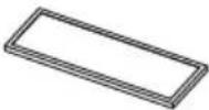 | Dry for 3 hours in sunlight or under fluorescent light.It is recommended to clean it every six months. (assuming 8 hours of daily use)Washing the filter with water could damage or deform it. |
PM1.0 filter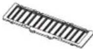 | Clean the filter without disassembling it.Submerge the PM1.0 filter in water, shaking it several times to clean it.If the filter is very dirty, soak it for 30 minutes in lukewarm water with mild detergent and rinse thoroughly with clean water. (Do not use acidic detergents such as citric acid.)It is recommended to clean it every six months.Dry it thoroughly in the shade for about a day. (If there is any remaining moisture, the buzzer will sound 7 times.)Drying with a hot air heater, such as a hair dryer or a heater, could damage or deform the filter.The inside of the filter is sharp, so do not rub or touch it directly. |
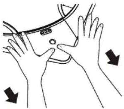
Cleaning the PM1.0 Sensor
PM1.0 Sensor
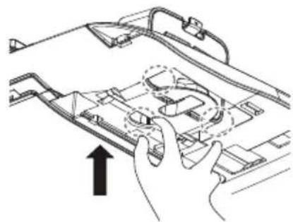
- As shown in the figure below, put your finger in the indicator.
natural_image
Diagram of hands operating a device with an arrow indicating direction (no text or symbols present)- Open the front panel and lower the PM1.0 Sensor case as shown in the figure below.
natural_image
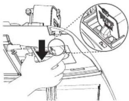
Hand operating a mechanical device with a magnified inset showing internal components (no text or symbols visible)- Once the PM1.0 Sensor case is lowered all the way, turn the PM1.0 Sensor case to secure it as shown in the figure below.
natural_image
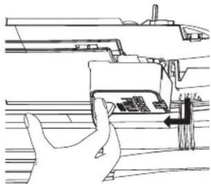
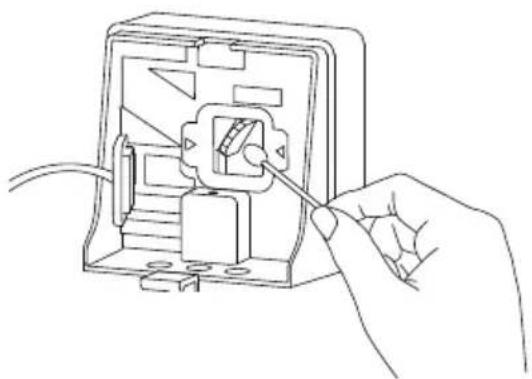
Line drawing of a hand pressing down on a mechanical component with an arrow indicating motion (no text or symbols)- Open the PM1.0 sensor cover on the side of the case.
natural_image
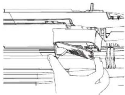
Line drawing of a hand holding a mechanical component, no text or symbols present- Use a slightly wet cotton swab to wipe dust off the lens, and then use a dry swab to remove the moisture.
natural_image
Line drawing of a hand holding a tool, interacting with a mechanical component (no text or symbols present)- Close the PM1.0 Sensor case cover, then install the PM1.0 Sensor case in its original position.
WARNING
- For safety, turn off the main power switch.
- Be careful not to drop the product when removing the PM1.0 Sensor corner cover.
- Be careful of falling accidents when cleaning the PM1.0 Sensor.
NOTE
- It is recommended to clean it every six months. (assuming 8 hours of daily use)
- PM1.0 Sensor is only included with Air purification panel.
- The feature may be changed according to the type of model.
- Some functions may not be supported, depending on the model.
Ceiling Cassette - 4Way
CAUTION
Before performing any maintenance, turn off the main power to the system.
Grille, Case, and Remote Control
■ Turn the system off before cleaning. To clean, wipe with a soft, dry cloth. Do not use bleach or abrasives.
NOTE
Supply power must be disconnected before cleaning the indoor unit.
Air Filters
The air filters behind the front grille should be checked and cleaned once every 2 weeks or more often if necessary.
■ Never use any of the followings:
• Water hotter than 40 °C.
Could cause deformation and/or discoloration.
• Volatile substances. Could damage the surfaces of the air conditioner.
- Remove the Air filters.
■ Take hold of the tab and pull slightly forward to remove the filter.
CAUTION
When the air filter is to be removed, do not touch the metal parts of the indoor unit. It may cause an injury.
- Clean dirt from the air filter using a vacuum cleaner or washing with water.
■ If dirt is conspicuous, wash with a neutral detergent in lukewarm water.
■ If hot water (40 °C or more) is used, it may be deformed.
- After washing with water, dry well in the shade.
■ Do not expose the air filter to direct sunlight or heat from a fire when drying it.
- Install the air filter.
Cleaning the deodorization filter/PM1.0 filter (Optional)
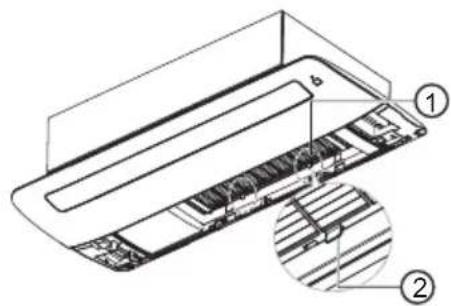
- Press the fixing hooks on both sides and open the front grille.
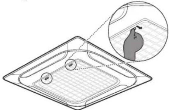
natural_image
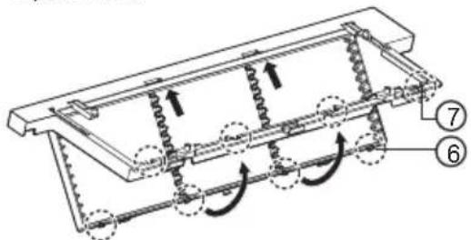
Diagram of a tray with two circular objects and an inset showing a magnified view of a fruit-like object (no text or symbols)- Remove PM1.0 filter by pressing the fixing hook.
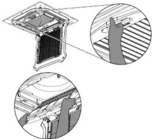
natural_image
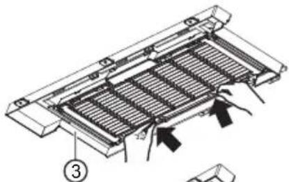
Technical diagram of a mechanical assembly with cross-sectional views and internal components (no text or symbols)- Remove the photocatalyst Deodorization filter by pulling upward.
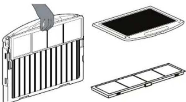
natural_image
Technical line drawings of a heat exchanger panel with handle, cover plate, and tray (no text or symbols)- After assembling in reverse order, close the front grille.
WARNING
For safety, turn off the main power switch.
CAUTION
- Be careful that the filter case is correctly assembled to the filter holder.
- Be careful not to drop the front grille when removing the filter.
- Do not wash the dust filter with hot water over 40 °C or volatile liquids.
- Do not wash the photocatalytic Deodorization filter in water.
- After cleaning the PM1.0 filter, the buzzer sounds 7 times if the water is not completely dry. Dry the filter thoroughly.
- Drying the filter near a fire or in direct sunlight may cause damage to the filter.
- Wear gloves during installation.
NOTE
- The quantity and type of filters provided by each model may differ.
- The feature may be changed according to the type of model.
- Some functions may not be supported, depending on the model.
Filter Information
| Filter Name Filter Description | |
Deodorization filter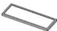 | Dry for 3 hours in sunlight or under fluorescent light.It is recommended to clean it every six months. (assuming 8 hours of daily use)Washing the filter with water could damage or deform it. |
PM1.0 filter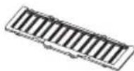 | Clean the filter without disassembling it.Submerge the PM1.0 filter in water, shaking it several times to clean it.If the filter is very dirty, soak it for 30 minutes in lukewarm water with mild detergent and rinse thoroughly with clean water. (Do not use acidic detergents such as citric acid.)It is recommended to clean it every six months.Dry it thoroughly in the shade for about a day. (If there is any remaining moisture, the buzzer will sound 7 times.)Drying with a hot air heater, such as a hair dryer or a heater, could damage or deform the filter.The inside of the filter is sharp, so do not rub or touch it directly. |
Cleaning the PM1.0 Sensor
PM1.0 Sensor
- Remove the PM1.0 Sensor corner cover on the front panel.
natural_image
Illustration of hands performing a medical or therapeutic procedure on a device (no text or symbols present)- Open the PM1.0 sensor case on the side of the PM1.0 Sensor case and remove the rubber cap.

- Use a cotton swab to wipe the dirt off the lens, and then use a dry swab to remove the moisture.
natural_image
Line drawing of hands inserting a plug into an electrical socket (no text or symbols)Tighten the rubber cap, close the PM1.0 sensor case, and assemble the PM1.0 Sensor corner cover to its original position.
① Rubber cap
② PM 1.0 sensor case
WARNING
- For safety, turn off the main power switch.
- Be careful not to drop the product when removing the PM1.0 Sensor corner cover.
- Be careful of falling accidents when cleaning the PM1.0 sensor.
NOTE
- It is recommended to clean it every six months. (assuming 8 hours of daily use)
- PM1.0 Sensor is only included with Air purification panel.
- The feature may be changed according to the type of model.
• Some functions may not be supported, depending on the model.
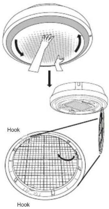
Ceiling Cassette - Round
CAUTION
Before performing any maintenance, turn off the main power to the system.
Grille, Case, and Remote Control
■ Turn the system off before cleaning. To clean, wipe with a soft, dry cloth. Do not use bleach or abrasives.
NOTE
Supply power must be disconnected before cleaning the indoor unit.
Air Filters
The air filters behind the front grille should be checked and cleaned once every 2 weeks or more often if necessary.
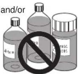
■ Never use any of the followings:
• Water hotter than 40 °C. Could cause deformation and/or discoloration.
• Volatile substances. Could damage the surfaces of the air conditioner.
- Remove the Air filters.
■ Take hold of the tab and pull slightly forward to remove the filter.
CAUTION
When the air filter is to be removed, do not touch the metal parts of the indoor unit. It may cause an injury.
- Clean dirt from the air filter using a vacuum cleaner or washing with water.
■ If dirt is conspicuous, wash with a neutral detergent in lukewarm water.
■ If hot water (40 °C or more) is used, it may be deformed.
- After washing with water, dry well in the shade.
■ Do not expose the air filter to direct sunlight or heat from a fire when drying it.
- Install the air filter.
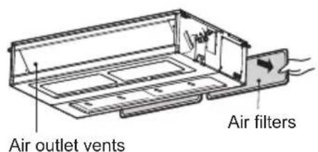
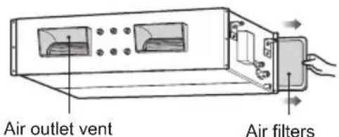
Ceiling Concealed Duct
CAUTION
Before performing any maintenance, turn off the main power to the system.
Grille, Case, and Remote Control
■ Turn the system off before cleaning. To clean, wipe with a soft, dry cloth. Do not use bleach or abrasives.
NOTE
Supply power must be disconnected before cleaning the indoor unit.
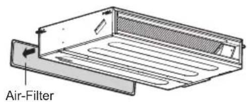
Air Filters
The air filters behind Indoor unit (the suction side) should be checked and cleaned once every 2 weeks or more often if necessary.
* The feature can be changed according to the type of model.
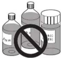
■ Never use any of the followings:
- Water hotter than 40 °C Could cause deformation and/or discoloration. - Volatile substances Could damage the surfaces of the air conditioner.
- Remove the Air filters.
■ Take hold of the tab and pull slightly forward to remove the filter.
CAUTION
When the air filter is to be removed, do not touch the metal parts of the indoor unit. It may cause an injury.
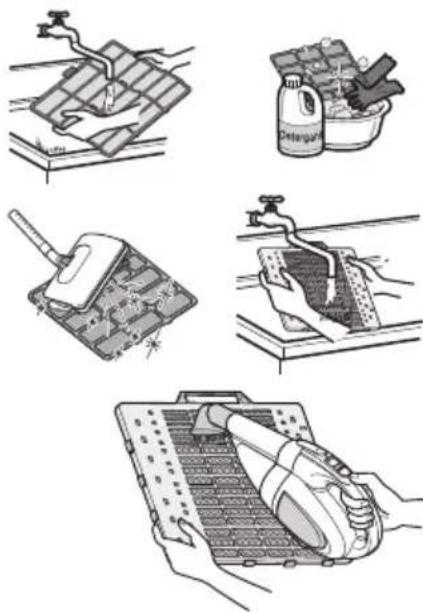
- Clean dirt from the air filter using a vacuum cleaner or washing with water.
■ If dirt is conspicuous, wash with a neutral detergent in lukewarm water.
If hot water (40 °C or more) is used, it may be deformed.
- After washing with water, dry well in the shade.
■ Do not expose the air filter to direct sunlight or heat from a fire when drying it.
- Install the air filter.
Art Cool Gallery Series
CAUTION
Before performing any maintenance, turn off the main power to the system, disconnect the circuit breaker and unplug the power cord.
Clean the unit with a soft dry cloth. Do not use bleach or abrasives.
CAUTION
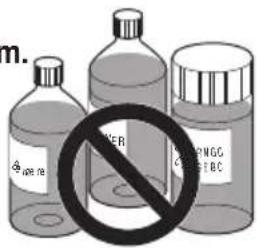
Never use any of these
• Water hotter than 40 °C. It may cause deformation and discoloration.
- Volatile substances. They may damage the surface of the air conditioner.

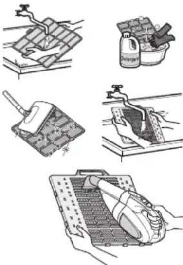
The air filters behind the front panel / grill should be checked and cleaned once in every 2 weeks or more often if necessary. To remove the filters see the self explanatory diagrams for each model type. Clean the filters with a vacuum cleaner or warm soapy water. If dirt is not easily removed, wash with a solution of detergent in luke warm water. Dry well in shade after washing and reinstall the filters back in place.
Plasma Filters
The plasma filters behind the air filter should be checked and cleaned once in every 3 months or more often if necessary. To remove the filters see the self explanatory diagrams for each model type. Clean the filters with a vacuum cleaner. If it is dirty wash it with water and dry well in shade an install back in place.
natural_image
Illustration showing five different cleaning and cleaning techniques: surface cleaning, spray bottle, circuit board installation, hand cleaning, and handheld device (no text or symbols present)Deodorizer Filters
Remove the deodorizer filters behind the air filter and expose them in direct sunlight for 2 hours.
And then insert these filters into original position.
Removal of Filters
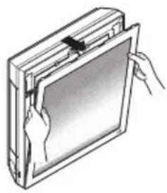
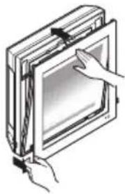
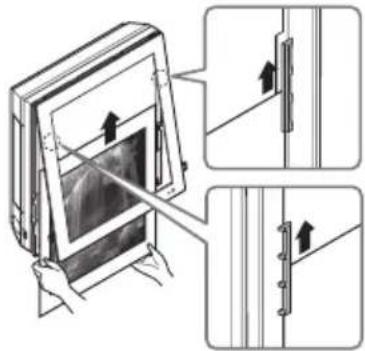
Art Cool Type :
Pull out the upper section of front panel and lift it up. Take out a filter with front panel held.
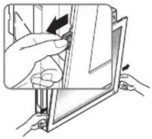
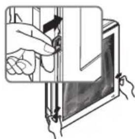
With PUSH button pressed, pull out grip to take out a plasma filter. Dry it completely in the shade after cleaning.
Then set a plasma filter and a filter orderly. Put the hook of front panel onto the hanger, in order to close the front panel.
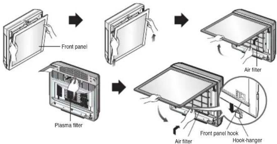
flowchart
graph TD
    A["Front panel"] --> B["Plasma filter"]
    B --> C["Air filter"]
    C --> D["Front panel hook"]
    D --> E["Hook-hanger"]
CAUTION
Don't touch this plasma filter within 10 seconds after opening the inlet grille, it may cause an electric shock.
How to replace picture & photograph
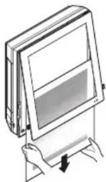
- Turn off power and then open the upper part of front panel.
natural_image
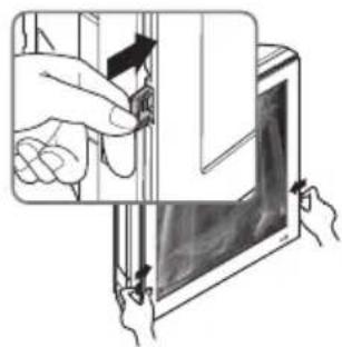
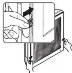
Illustration of a hand inserting a card into a rectangular frame (no text or symbols)- Pull out the both links of lower part of front panel, as described in the below picture.
natural_image
Illustration of hands installing or adjusting a component on a device (no text or symbols visible)- Push and close the top part of the front panel and then pull the bottom part of the panel forward until it is secured.
natural_image
Illustration of hands interacting with a screen or tablet device (no text or symbols visible)- Take out picture.
natural_image
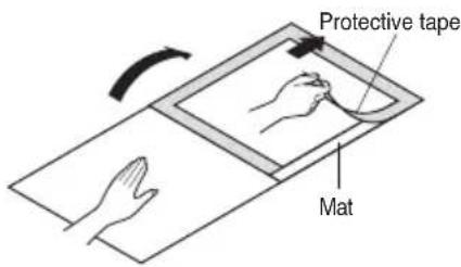
Illustration of hands holding a rectangular panel with a screen, no text or symbols present- Turn upside-down of the picture and turn over mat, then take off a protective tape attached at the mat.
- Place the picture/photograph between the exited picture and mat. (Recommended size of a photo/picture: 450 mm x 450 mm)
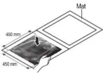
- Cover mat and press down with hand(s) until contacting closely.
natural_image
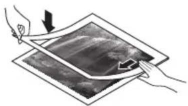
Illustration of two hands holding a tablet with a screen showing a landscape (no text or symbols)- Slide the photo graph/drawing requested under both hanger parts as following, and fix them. Press the front panel lightly to close.
- Push both links of lower part of panel inside and fix it. Then turn on.
natural_image
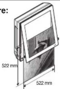
Illustration of hands inserting a device into a tablet (no text or symbols visible)※ In case a mat is not used, recommended size of a photo/picture:
522 mm × 522 mm
When powering on after replacing filter and picture, the front panel doesn't intervene.
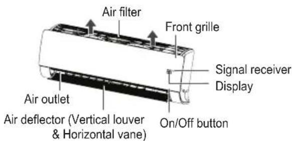
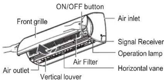
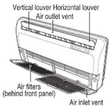
Wall Mounted
CAUTION
Before performing any maintenance, turn off the main power to the system.
Never use any of the followings:
• Water hotter than 40 °C. Could cause deformation and/or discoloration.
- Volatile substances. Could damage the surfaces of the air conditioner.
Air Filters
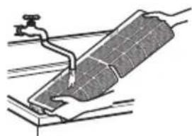
The air filters behind the front panel / grill should be checked and cleaned once in every 2 weeks or more often if necessary. To remove the filters see the self explanatory diagrams for each model type. Clean the filters with a vacuum cleaner or warm soapy water. If dirt is not easily removed, wash with a solution of detergent in luke warm water. Dry well in shade after washing and reinstall the filters back in place.
natural_image
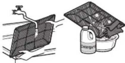
Diagram of a solar panel installation with a water tap and pipe (no text or symbols)Clean the air filter
Clean the air filter once every 2 weeks or more if necessary.
- Turn off the power and unplug the power cord.
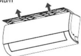
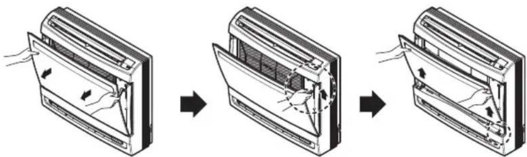
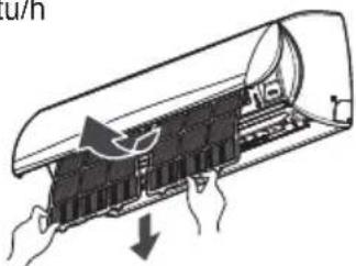
- 5\~24 kBtu/h : Hold the knob of air filter, Lift it up slightly.
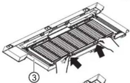
30\~36 kBtu/h : Open the front panel as shown.
5\~24 kBtu/h
30\~36 kBtu/h
* The feature can be changed according to type of model.
- 5\~24 kBtu/h : Hold the knob of air filter, Lift it up slightly and remove it from the unit. 30\~36 kBtu/h : Pull the filter tab slightly forward to remove the air filter.
5\~24 kBtu/h
natural_image
Technical line drawing of a cylindrical component with internal structure and two upward arrows indicating force or movement (no text or symbols)30\~36 kBtu/h

natural_image
Diagram of a door with hands holding the lid and down force, showing internal components (no text or symbols)* The feature can be changed according to type of model.
- Clean the filter with a vacuum cleaner or with warm water.
- If dirt is difficult to remove, wash the filter in lukewarm water with detergent.
- Dry the filter in the shade.
NOTE
The air filter can be broken when it is bended.
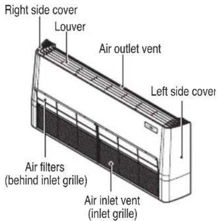
Convertible
CAUTION
Before performing any maintenance, turn off the main power to the system.
Grille, Case, and Remote Control
■ Turn the system off before cleaning.
To clean, wipe with a soft, dry cloth. Do not use bleach or abrasives.
NOTE
Supply power must be disconnected before cleaning the indoor unit.
■ Never use any of the followings:
• Water hotter than 40 °C. Could cause deformation and/or discoloration.
• Volatile substances
Could damage the surfaces of the air conditioner.
Air Filters
The air filters behind the front grille should be checked and cleaned once in every 2 weeks or more often if necessary.
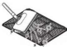
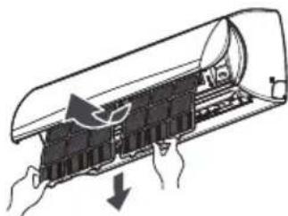
- Lift the front access panel and pull the filter tab slightly forward to remove the filter.
- Clean the filter with a vacuum cleaner or warm, soapy water.
- If dirt is conspicuous, wash with a solution of detergent in lukewarm water.
- If hot water (40 °C or more) is used, it may be deformed.
- After washing with water, dry well in the shade.
- Re-install the air filter.
Console
CAUTION
Before performing any maintenance, turn off the main power to the system, disconnect the circuit breaker and unplug the power cord.
Cleaning of Panel and filters
Clean the unit with a soft dry cloth. Do not use bleach or abrasives.
CAUTION
Never use any of these
- Water hotter than 40 °C. It may cause deformation and discoloration.
- Volatile substances. They may damage the surface of the air conditioner.
Air Filters
The air filters behind the front panel / grill should be checked and cleaned once in every 2 weeks or more often if necessary. To remove the filters see the self explanatory diagrams below. Clean the filters with a vacuum cleaner or warm soapy water.
If dirt is not easily removed, wash with a solution of detergent in luke warm water.
Dry well in shade after washing and reinstall the filters back in place.
Allergy Filter
Remove the Allergy Filter behind the air filter and expose them in direct sunlight for 2 hours.
And then insert these filters into original position.
natural_image
Illustration of a solar panel being cleaned with a water bottle and a container of food (no text or symbols)Removal of Grille
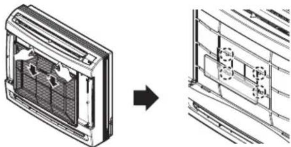
- Open the front grille by pulling forward
- Then pull out the link of grille from groove in front panel.
- Then pull out 2 hinges of grille from grooves in front panel.
Removal of Filters
- Pull down the filter tab slightly to remove the air filter.
- Hold the tabs of the frame, and remove the claws in 4 places.
natural_image
Diagram showing airflow or ventilation system transformation from a rectangular device to a grid-patterned panel (no text or symbols)When the air conditioner is not going to be used for a long time
When it is not going to be used for a long time.

Operate the air conditioner at the following settings for 2 to 3 hours.
- Type of operation: Fan operation mode.
• This will dry out the internal mechanisms.

Turn off the breaker.

CAUTION
Turn off the breaker when the air conditioner is not going to be used for a long time.
Dirt may collect and may cause a fire.
Helpful information
The air filters and your electric bill. If the air filters become clogged with dust, the cooling capacity will drop, and 6 % of the electricity used to operate the air conditioner will be wasted.
When the air conditioner is to be used again.

Clean the air filter and install it in the indoor unit.

Check that the air inlet and outlet of the indoor/outdoor unit are not blocked.

Check that the ground wire is connected correctly. It may be connect to the indoor unit side.
Operation Tips
Do not overcool the room.
This is not good for the health and wastes electricity.
Make sure that the doors and windows are shut tight.
Avoid opening doors and windows as much as possible to keep the cool air in the room.
Keep blinds or curtains closed.
Do not let direct sunshine enter the room when the air conditioner is in operation.
Clean the air filter regularly.
Blockages in the air filter reduce the airflow and lower cooling and dehumidifying effects. Clean at least once every two weeks.
Keep the room temperature uniform.
Adjust the vertical and horizontal airflow direction to ensure a uniform temperature in the room.
Ventilate the room occasionally.
Since windows are kept closed, it is a good idea to open them and ventilate the room now and then.
Before you call for service...
Troubleshooting Tips! Save time and money!
Check the following points before requesting repairs or service.... If the malfunction persist, please contact your dealer.
| The air conditioner does not operate. | ·Have you made a mistake in timer operation? ·Has the fuse blown or has the circuit breaker been tripped? |
| The room has a peculiar odor. | ·Check that this is not a damp smell exuded by the walls, carpet, furniture or cloth items in the room. |
| It seems that condensation is leaking from the air conditioner. | ·Condensation occurs when the airflow from the air conditioner cools the warm room air. |
| Air conditioner does not operate for about 3 minutes when restart. | ·This is the protector of the mechanism. ·Wait about three minutes and operation will begin. |
| Does not cool or heat effectively. | ·Is the air filter dirty? See air filter cleaning instructions. ·The room may have been very hot when the room air conditioner was first turned on. Allow time for it to cool down. ·Has the temperature been set incorrectly? ·Are the indoor unit's air inlet or outlet vents obstructed? |
| The air conditioner operation is noisy. | ·For a noise that sounds like water flowing. - This is the sound of freon flowing inside the air conditioner unit. ·For a noise that sounds like the compressed air releasing into atmosphere. - This is the sound of the dehumidifying water being processed inside the air conditioning unit. |
| Crack sound is heard. | ·This sound is generated by the expansion/ constriction of the front panel, etc. due to changes of temperature. |
| Remote control display is faint, or no display at all. | ·Are the batteries depleted? ·Are the batteries inserted in the opposite (+) and (-) directions? |
| The air conditioner changes generated airflow during operation. | ·When the air conditioner reaches the desired temperature, the airflow rate reduces in order to avoid generating cool airflow during heating, or to minimize energy consumption and indoor humidity change during cooling. - This symptom is normal. |
| The buzzer sounds. (7 times) | ·Is the suction panel completely closed? Close the suction grille completely. ·Is the water completely dried after cleaning PM1.0 filter? If moisture remains, let it dry in the shade for about a day. ·Is PM1.0 filter film torn? Contact the LG Electronics Service Center. |
NOTE
• Water resistant: The outdoor side of this appliance is WATER RESISTANT.
The indoor side is not water resistant and should not be exposed to excess water.
- Some functions may not be supported, depending on the model.
MANUALE DEL'UTENTE
natural_image
Line drawing of a mechanical tool or brush inside a cylindrical container (no text or symbols)NOTA
natural_image
Line drawing of a mobile phone with keypad and display (no text or symbols)natural_image
Pure electrical circuit lines without any symbols① Marcatore
② Pre-filtro
③ Caso del filtro

natural_image
Technical diagram of a mechanical component with internal ribs and mounting features (no text or symbols)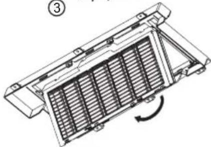
natural_image
Technical line drawing of a heat exchanger or cooling unit with internal grating and cooling fins (no text or symbols)
natural_image
Technical line drawing of a mechanical device with a hand operating the component (no text or symbols present)natural_image
Diagram of hands operating a device with a highlighted internal component and an upward arrow indicating motion (no text or symbols present)natural_image
Hand operating a mechanical device with a magnified inset showing internal components (no text or symbols visible)natural_image
Technical line drawing of a mechanical assembly with a hand holding a component (no text or symbols visible)natural_image
Line drawing of a hand holding a mechanical component, no text or symbols presentnatural_image
Line drawing of a hand using a tool to adjust or install a mechanical component (no text or symbols present)natural_image
Diagram of a tray with two circular objects and an inset showing a hand holding a small object (no text or symbols present)natural_image
Technical illustration of a mechanical component with cross-sectional views and internal structure (no text or symbols)natural_image
Technical line drawings of a heat exchanger with internal compartments and a separate panel (no text or symbols)natural_image
Illustration of hands performing a medical or therapeutic procedure on a device (no text or symbols present)natural_image
Line drawing of a hand inserting a cable into an open electrical outlet (no text or symbols)Art Cool Gallery Series
ATTENZIONE
natural_image
Illustration of five different household cleaning and cleaning tasks: washing machine, cleaning board, using a tool, cleaning board with water drop, and using a tool kit (no text or symbols present)natural_image
Illustration of hands holding a tablet device (no text or symbols visible)natural_image
Illustration of hands installing or adjusting a component on a device (no text or symbols visible)natural_image
Illustration of hands inserting a component into a rectangular frame (no text or symbols)natural_image
Illustration of hands holding a flat-screen monitor with a slide, no text or symbols presentnatural_image
Illustration of two hands holding a tablet with a scroll, showing a hand pressing down on the screen (no text or symbols present)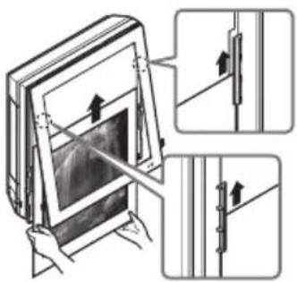
natural_image
Illustration of a hand inserting a small object into a device, with hands holding the component (no text or symbols visible)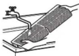
natural_image
Diagram of a mechanical component with a lever and pipe, no visible text or symbolsnatural_image
Technical line drawing of a mechanical component with two arrows indicating upward motion (no text or symbols)30\~36 kBtu/h
natural_image
Diagram of a car air conditioner unit with airflow arrows indicating internal components (no text or symbols)Filtri
natural_image
Illustration of three different household cleaning methods: a faucet, a solar panel with a bucket, and a detergent bottle (no text or symbols present)natural_image
Line drawing of a mechanical device with a handle and lever (no text or symbols)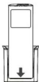
natural_image
Line drawing of a mobile phone with keypad and control panel (no text or symbols)- Please select the code depend on your feeling.
natural_image
Pure electrical circuit lines without any symbolsnatural_image
Diagram of a mechanical assembly with a magnified inset showing a component labeled '上' (upper section), no text or symbols present.natural_image
Diagram of a grid-patterned rectangular structure with curved lines and a cursor icon pointing to it (no text or symbols)natural_image
Technical line drawing of a refrigerated air conditioner unit with a magnified inset showing internal structure (no text or symbols)

natural_image
Technical diagram of a mechanical component with internal ribs and mounting holes (no text or symbols)
natural_image
Technical line drawing of a heat exchanger or cooling unit with internal heat flow arrows (no text or symbols)
natural_image
Technical line drawing of a mechanical device with a hand operating it (no text or symbols present)natural_image
Diagram of hands operating a device with a highlighted internal component and an upward arrow indicating motion (no text or symbols present)natural_image
Hand operating a mechanical device with a magnified inset showing internal components (no text or symbols visible)natural_image
Line drawing of a hand holding a small object with an arrow indicating direction (no text or symbols)natural_image
Line drawing of a hand holding a mechanical component, no text or symbols presentnatural_image
Line drawing of a hand holding a tool interacting with a mechanical component (no text or symbols)natural_image
Diagram of a tray with two spheres and a magnified inset showing a hand holding a finger (no text or symbols)natural_image
Technical illustration of a mechanical component with cross-sectional views and close-ups (no text or symbols)natural_image
Technical line drawings of a heat exchanger with internal compartments and a separate display panel (no text or symbols)natural_image
Illustration of hands performing a medical or emergency procedure on a device (no text or symbols present)natural_image
Line drawing of a hand inserting a cable into an open electrical outlet (no text or symbols)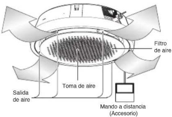
Art Cool Gallery Series
PRECAUCIÓN
natural_image
Illustration of hands holding a blank sheet with a scroll, no text or symbols presentnatural_image
Illustration of a hand inserting a small object into a device (no text or symbols visible)natural_image
Illustration of hands interacting with a digital display panel (no text or symbols visible)natural_image
Illustration of a person pressing down on a rectangular panel with a downward arrow (no text or symbols)natural_image
Illustration of hands holding a pen over a printed document with arrows indicating motion (no text or symbols)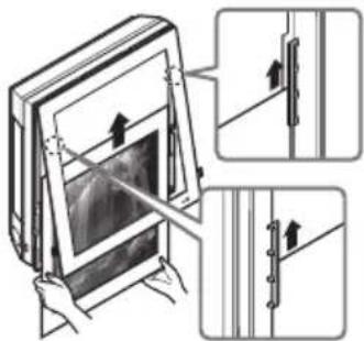
natural_image
Illustration of hands inserting a cable into a device (no text or symbols visible)natural_image
Technical line drawing of a mechanical component with two upward arrows indicating force or direction (no text or symbols)30\~36 kBtu/h
natural_image
Diagram of a car air conditioner unit with hands holding the lid and cooling fan (no text or symbols)natural_image
Illustration of a solar panel being pumped by a faucet and a container with a bag labeled 'Deltargu' (no text or symbols on the diagram itself)natural_image
Line drawing of a mechanical device with a handle and internal components (no text or symbols)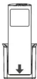
natural_image
Front view of a mobile phone with a blank screen and 16 button layout (no text or symbols)natural_image
Pure electrical circuit lines without any symbolsnatural_image
Diagram of a mechanical assembly with a key inserted into a housing (no text or symbols)Bouton ON/OFF
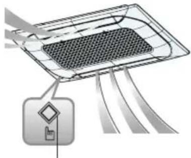
natural_image
Diagram of a device with a grid pattern and directional arrows, no text or symbols presentBouton ON/OFF
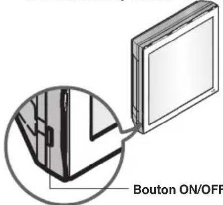
natural_image
Technical line drawing of a wall-mounted air conditioner unit with a magnified inset showing internal components (no text or symbols)Bouton ON/OFF

natural_image
Technical diagram of a mechanical component with internal ribs and mounting holes (no text or symbols)
natural_image
Technical line drawing of a heat exchanger or cooling unit with internal grid structure and rotation arrow (no text or symbols)
natural_image
Technical line drawing of a mechanical device with a hand operating the component (no text or symbols present)natural_image
Diagram of a hand inserting a component into a device, showing internal structure and wiring (no text or symbols)natural_image
Hand holding a mechanical component with a magnified inset showing internal components (no text or symbols)natural_image
Line drawing of a hand holding a mechanical component with an arrow indicating direction (no text or symbols)natural_image
Line drawing of a hand holding a mechanical component, no text or symbols presentnatural_image
Line drawing of a hand holding a tool interacting with a mechanical component (no text or symbols)natural_image
Diagram of a kitchen sink with two circular objects and a magnified inset showing a finger pointing to a surface (no text or symbols)natural_image
Technical illustration of a mechanical component with cross-sectional views and detail insets (no text or symbols)natural_image
Technical line drawings of a heat exchanger panel with handle, cover plate, and tray (no text or symbols)natural_image
Illustration of hands performing a medical procedure on a device (no text or symbols present)natural_image
Line drawing of a hand inserting a switch into an open electrical outlet (no text or symbols)Art Cool Gallery Series

ATTENTION
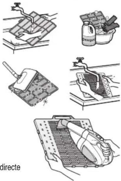
natural_image
Illustration of hands holding a blank sheet with a clip, no text or symbols presentnatural_image
Illustration of hands installing or adjusting a door panel (no text or symbols visible)natural_image
Illustration of hands interacting with a rectangular device (no text or symbols visible)- Retirez l'image.
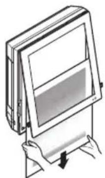
natural_image
Illustration of hands holding a flatboard with a screen, no text or symbols presentnatural_image
Illustration of two hands holding a tablet with arrows indicating motion (no text or symbols)natural_image
Illustration of a hand inserting a cable into a device (no text or symbols visible)natural_image
Diagram of a solar panel being placed on a surface with a water tap (no text or symbols)natural_image
Technical line drawing of a mechanical component with two arrows indicating upward motion (no text or symbols)30\~36 kBtu/h
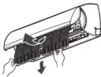
natural_image
Diagram of a car air conditioner unit with airflow arrows indicating airflow direction (no text or symbols)natural_image
Illustration of three different household cleaning methods: a water tap, a tray with cleaning cloth, and a bag filled with food (no text or symbols)Dépose de la grille
natural_image
Line drawing of a mechanical device with a handle and lever (no text or symbols)
Bedienung
natural_image
Line drawing of a mobile phone with keypad and display (no text or symbols)natural_image
Pure electrical circuit lines without any symbolsnatural_image
Diagram of a device with a lock and gear mechanism, no text or symbols presentEin/Aus-Taste
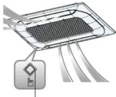
natural_image
Diagram of a device with a grid pattern and directional arrows, no text or symbols presentEin/Aus-Taste
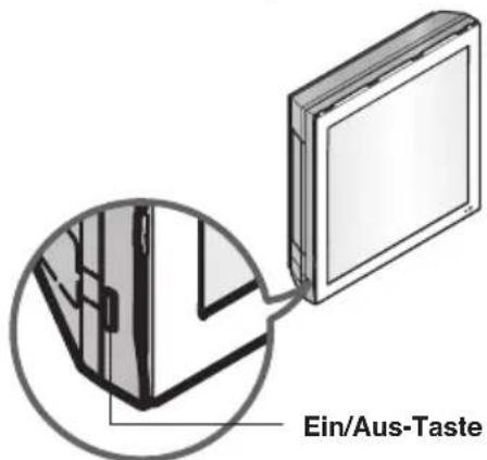
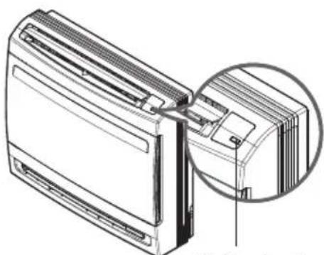
natural_image
Technical line drawing of a front-mounted air conditioner unit with a magnified inset showing internal components (no text or symbols)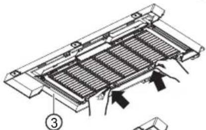
natural_image
Technical diagram of a mechanical component with internal ribs and mounting features (no text or symbols)
natural_image
Technical line drawing of a heat exchanger or cooling unit with internal blades and cooling fins (no text or symbols)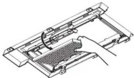
natural_image
Technical line drawing of a mechanical device with a hand operating the component (no text or symbols present)natural_image
Diagram of hands operating a device with a highlighted internal component and an upward arrow indicating motion (no text or symbols present)natural_image
Illustration of a hand using a tool to adjust or install a mechanical component, with an inset showing a close-up of the component (no text or symbols visible)natural_image
Line drawing of a hand holding a mechanical component with an arrow indicating direction (no text or symbols)natural_image
Line drawing of a hand holding a mechanical component, no text or symbols presentnatural_image
Line drawing of a hand holding a tool interacting with a mechanical component (no text or symbols)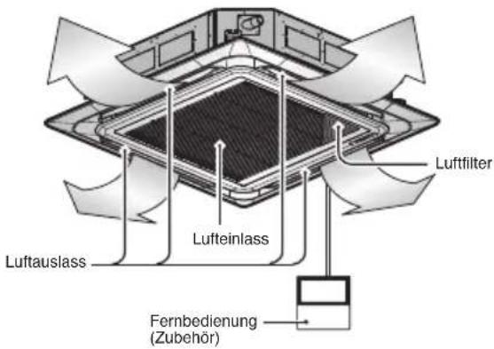
natural_image
Diagram of a tray with two circular objects and an inset showing a hand holding a curved object (no text or symbols)natural_image
Technical illustration of a mechanical component with cross-sectional views and close-ups (no text or symbols)natural_image
Technical line drawings of a vehicle air vent, showing front panel, back panel, and side tray (no text or symbols)natural_image
Illustration of hands performing a medical procedure on a device (no text or symbols present)natural_image
Line drawing of a hand inserting a cable into an open electrical outlet (no text or symbols)Art Cool Gallery Series
⚠️ ACHTUNG
natural_image
Illustration of hands holding a flatboard device (no text or symbols visible)natural_image
Illustration of hands holding a blank rectangular panel with a curved arrow indicating rotation (no text or symbols)natural_image
Illustration of hands installing or adjusting a component on a tablet device (no text or symbols visible)natural_image
Illustration of hands interacting with a digital display panel (no text or symbols visible)natural_image
Illustration of two hands holding a tablet with arrows indicating motion or movement (no text or symbols)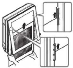
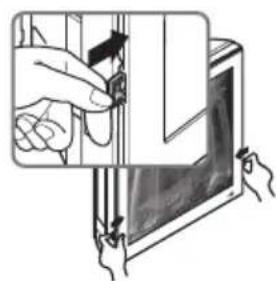
natural_image
Illustration of hands inserting a device into a tablet (no text or symbols visible)natural_image
Diagram of a mechanical component with a pipe and lever, no visible text or symbolsDen Luftfilter reinigen
natural_image
Technical line drawing of a car air duct or duct component with two upward arrows indicating flow direction (no text or symbols)30\~36 kBtu/h
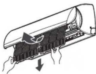
natural_image
Diagram of a car air conditioner unit with hands operating it, showing internal components and airflow direction (no text or labels)Luftfilter
natural_image
Illustration of three different household cleaning tasks: a water tap, a container with a brush, and a detergent bottle (no text or symbols present)Anti-Allergen-Filter
natural_image
Line drawing of a mechanical device with a handle and lever (no text or symbols)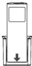
Μέθοδος Λειτουργίας
natural_image
Line drawing of a mobile phone with keypad and control panel (no text or symbols)natural_image
Pure electrical circuit lines without any symbols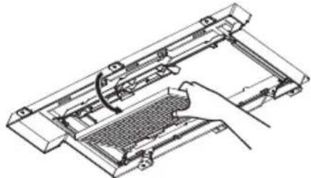
natural_image
Technical line drawing of a mechanical device with a hand operating the component (no text or symbols present)natural_image
Diagram of a hand pressing a component on a device, showing internal structure and an upward arrow (no text or symbols)natural_image
Hand holding a mechanical component with a magnified inset showing internal components (no text or symbols)natural_image
Line drawing of a hand holding a mechanical component with an arrow indicating direction (no text or symbols)natural_image
Line drawing of a hand holding a mechanical component, no text or symbols presentnatural_image
Line drawing of a hand holding a tool near a mechanical component (no text or symbols)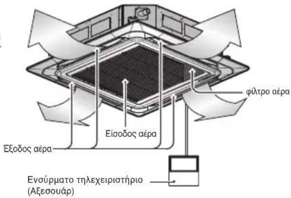
natural_image
Diagram of a tray with two circular objects and an inset showing a hand holding a fruit (no text or symbols)natural_image
Technical illustration of a mechanical component with cross-sectional views and close-ups (no text or symbols)natural_image
Technical line drawings of a heat exchanger panel with handle, cover plate, and tray (no text or symbols)natural_image
Illustration of hands performing a medical or therapeutic procedure on a device (no text or symbols present)natural_image
Line drawing of a hand inserting a cable into an open electrical socket (no text or symbols)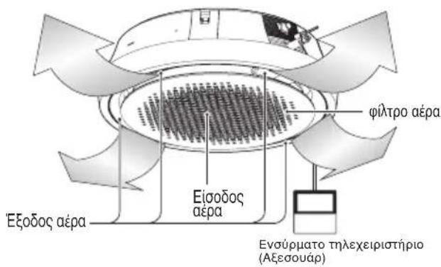
natural_image
Illustration of a roof drainage system with a faucet and tiled roof (no text or symbols)
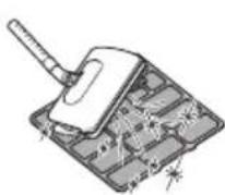
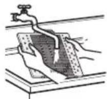
natural_image
Illustration of a hand holding a water tank with a faucet, no text or symbols present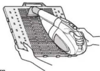
natural_image
Illustration of hands using a handheld device to interact with a grid-patterned device (no text or symbols visible)natural_image
Illustration of hands holding a blank sheet with a clip, no text or symbols presentnatural_image
Illustration of hands installing or adjusting a component on a device panel (no text or symbols visible)natural_image
Illustration of two hands inserting a rectangular device into a screen (no text or symbols visible)natural_image
Illustration of hands holding a tilted rectangular object with a screen, no text or symbols presentnatural_image
Illustration of hands holding a tablet with a screen, showing a magnified view of the screen (no text or symbols present)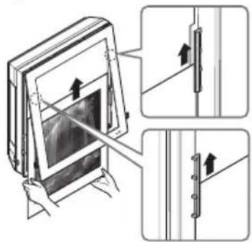

natural_image
Illustration of a hand inserting a component into a device (no text or symbols visible)φίλτρα αέρα
natural_image
Diagram of a solar panel installation with a water tap and pipe (no text or symbols)natural_image
Technical line drawing of a car air duct or duct assembly with two upward arrows indicating flow direction (no text or symbols present)30\~36 kBtu/h
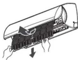
natural_image
Diagram of a car air conditioner unit with hands holding the lid and cooling system inside (no text or symbols)natural_image
Illustration of three different household cleaning methods: a water tap, a plastic bag with contents, and a spray bottle filled with greenery (no text or symbols)natural_image
Line drawing of a laboratory brush with a handle and spout (no text or symbols)POZNÁMKA
natural_image
Front view of a mobile phone with keypad and display (no text or symbols)natural_image
Simple line drawing of a Wi-Fi icon above a horizontal line with two small dots, no text or symbols present.natural_image
Diagram of a device with a lock and folder, showing internal components and a magnified view of the lock (no text or symbols present)Tlačítko pro ZAPNUTÍ/VYPNUTÍ (ON/OFF)
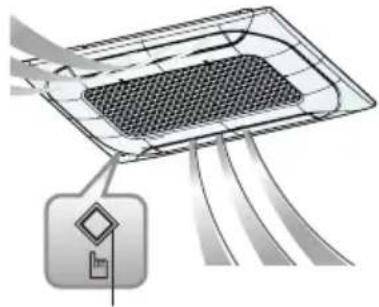
natural_image
Diagram of a smart grid device with connecting cables and a control panel (no text or symbols)Tlačítko pro ZAPNUTÍ/VYPNUTÍ (ON/OFF)
<Řada Art Cool Gallery>
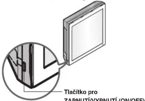

natural_image
Technical line drawing of a wall-mounted air conditioner unit with a magnified inset showing internal components (no text or symbols)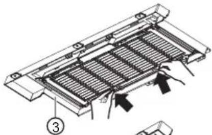
natural_image
Technical diagram of a mechanical component with internal channels and arrows indicating motion (no text or symbols)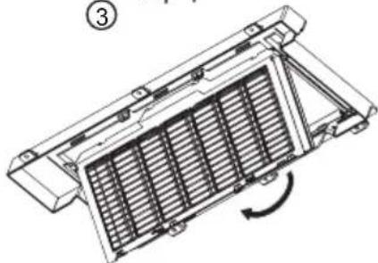
natural_image
Technical line drawing of a mechanical component with internal grating and mounting bracket (no text or symbols)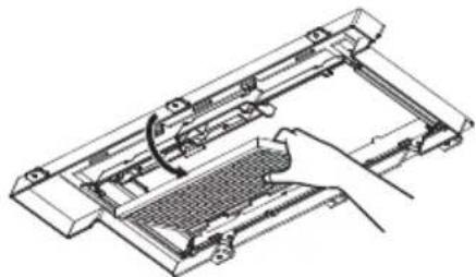
natural_image
Technical line drawing of a mechanical device with a hand operating the component (no text or symbols present)natural_image
Diagram of hands operating a device with an arrow indicating direction (no text or symbols present)natural_image
Hand operating a mechanical device with a magnified inset showing internal components (no text or symbols visible)natural_image
Line drawing of a hand pressing down on a mechanical component with an arrow indicating motion (no text or symbols)natural_image
Line drawing of a hand holding a mechanical component, no text or symbols presentnatural_image
Line drawing of a hand holding a tool interacting with a mechanical component (no text or symbols)natural_image
Diagram of a tray with two circular objects and a magnified inset showing a hand holding a finger (no text or symbols)natural_image
Technical illustration of a mechanical component with cross-sectional views and internal structure (no text or symbols)natural_image
Technical line drawings of a heat exchanger panel with handle, cover plate, and tray (no text or symbols)natural_image
Illustration of hands performing a medical or therapeutic procedure on a device (no text or symbols present)natural_image
Line drawing of a hand inserting a switch into an open electrical socket (no text or symbols)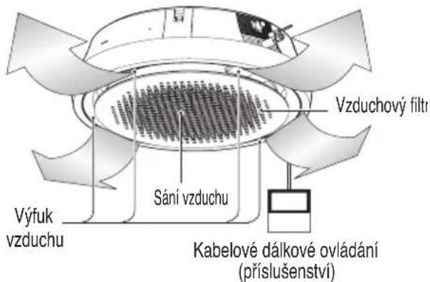
natural_image
Four-panel illustration showing different methods of cleaning or cleaning a solar panel, including surface treatment, cleaning, and surface finish (no text or symbols)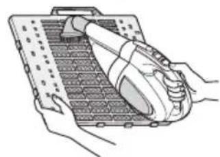
natural_image
Illustration of hands holding a device with a pen inserted, no text or symbols visiblenatural_image
Illustration of a hand inserting a card into a rectangular frame (no text or symbols)natural_image
Illustration of hands installing or adjusting a door panel with a pencil (no text or symbols visible)natural_image
Illustration of hands interacting with a rectangular device or frame (no text or symbols visible)- Vyjměte obrázek.
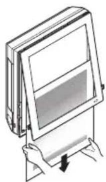
natural_image
Illustration of hands holding a blank rectangular panel with a downward arrow indicating compression (no text or symbols)natural_image
Illustration of hands holding a tablet with a magnified view of the screen (no text or symbols)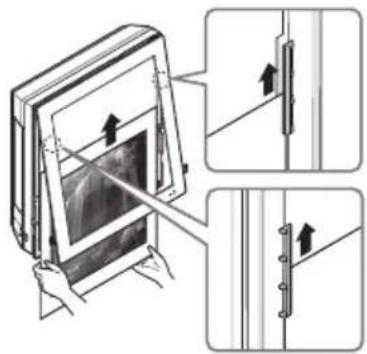
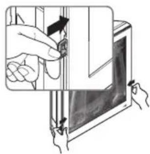
natural_image
Illustration of a hand inserting a small object into a device, with hands holding a tool (no text or symbols visible)natural_image
Diagram of a mechanical component with a pipe and lever, no visible text or symbolsnatural_image
Technical line drawing of a car air duct or duct assembly with two upward arrows indicating flow direction (no text or symbols present)30\~36 kBtu/h
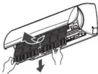
natural_image
Diagram of a car air conditioner unit with hands and airflow arrows indicating airflow direction (no text or symbols)Vzduchové filtry
natural_image
Line drawing of a mechanical device with a handle and internal components (no text or symbols)OPMERKING
natural_image
Line drawing of a mobile phone with keypad and control panel (no text or symbols)natural_image
Pure electrical circuit lines without any symbols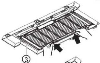
natural_image
Technical diagram of a mechanical component with internal channels and directional arrows (no text or symbols)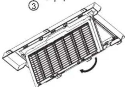
natural_image
Technical line drawing of a heat exchanger or cooling unit with internal blades and mounting brackets (no text or symbols)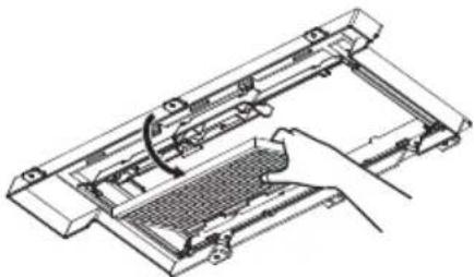
natural_image
Technical line drawing of a mechanical device with a hand operating the component (no text or symbols present)① PM 1.0-filter
② Handgreep
③ Filterhouder
④ Deodoriserend filter
⑤ Haak
⑥ Vierkant gat
⚠ WAARSCHUWING
natural_image
Diagram of hands operating a device with a highlighted internal component and an upward arrow indicating motion (no text or symbols present)natural_image
Illustration of a hand using a tool to adjust or install a mechanical component, with an inset showing a close-up of the component (no text or symbols present)natural_image
Technical line drawing of a mechanical assembly with hand and tool (no text or symbols)natural_image
Line drawing of a hand holding a mechanical component, no text or symbols presentnatural_image
Line drawing of a hand holding a tool interacting with a mechanical component (no text or symbols)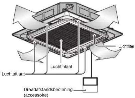
natural_image
Technical illustration of a mechanical component with cross-sectional views and close-ups (no text or symbols)natural_image
Technical line drawings of a heat exchanger panel, its top view, and its internal components (no text or symbols)natural_image
Illustration of hands performing a medical procedure on a device (no text or symbols present)natural_image
Line drawing of a hand inserting a cable into an open electrical socket (no text or symbols)natural_image
Illustration of hands holding a blank sheet with a black clip, no text or symbols presentnatural_image
Illustration of hands installing or adjusting a component on a device panel (no text or symbols visible)natural_image
Illustration of hands interacting with a screen or tablet device (no text or symbols visible)natural_image
Illustration of a person holding a blank board with a downward arrow, no text or symbols presentnatural_image
Illustration of hands holding a tablet with a magnified view of the screen (no text or symbols)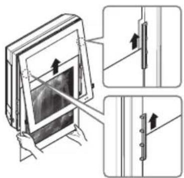
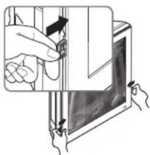
natural_image
Illustration of a hand inserting a small object into a device panel (no text or symbols visible)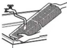
natural_image
Technical line drawing of a mechanical component with a lever and base plate (no text or symbols)Reinig de luchtfilter
natural_image
Technical line drawing of a car air duct or duct assembly with two upward arrows indicating flow direction (no text or symbols present)30\~36 kBtu/h

natural_image
Diagram of a car air conditioner unit with hands operating it, showing internal components and airflow direction (no text or labels)natural_image
Illustration of three different cleaning or cleaning methods: a water tap, a container with a brush, and a detergent bottle (no text or symbols present)Rooster verwijderen
natural_image
Line drawing of a mechanical device with a handle and lever (no text or symbols)UWAGA
natural_image
Line drawing of a mobile phone with keypad and display screen (no text or symbols)natural_image
Pure electrical circuit lines without any symbolsnatural_image
Diagram of a device with a lock and handle, showing internal components and a close-up view (no text or symbols)natural_image
Diagram of a device with mesh insulation and connecting wires, no text or symbols presentnatural_image
Technical line drawing of a wall-mounted air conditioner unit with a magnified inset showing internal components (no text or symbols)natural_image
Diagram of hands operating a device with a highlighted internal component and an upward arrow indicating motion (no text or symbols present)natural_image
Hand holding a mechanical component with a magnified inset showing a close-up of a car interior (no text or symbols visible)natural_image
Line drawing of a hand holding a mechanical component with an arrow indicating direction (no text or symbols)natural_image
Line drawing of a hand holding a mechanical component, no text or symbols presentnatural_image
Line drawing of a hand holding a tool interacting with a mechanical component (no text or symbols)natural_image
Diagram of a tennis court with two balls and a magnified inset showing a finger pressing on the surface (no text or symbols)natural_image
Technical illustration of a mechanical component with cross-sectional views and close-ups (no text or symbols)natural_image
Technical line drawings of a car air vent assembly, showing front panel, top panel, and side tray (no text or symbols)natural_image
Illustration of hands performing a medical procedure on a patient's face (no text or symbols present)natural_image
Line drawing of a hand inserting a switch into an open electrical socket (no text or symbols)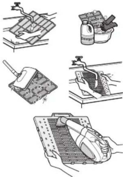
natural_image
Illustration of five different cleaning or cleaning techniques: surface water treatment, spray bottle, cleaning board, handwashing, and cleaning device (no text or symbols present)Wyjmowanie filtrów
Typ "Art Cool":
natural_image
Illustration of a hand holding a rectangular panel with a black clip, no text or symbols presentnatural_image
Illustration of hands installing or adjusting a panel with arrows indicating movement (no text or symbols)natural_image
Illustration of hands inserting a rectangular device into a frame (no text or symbols)natural_image
Illustration of hands holding a rectangular object with a gradient screen, no text or symbols presentnatural_image
Illustration of hands holding a tablet with a magnified view showing internal tissue (no text or symbols)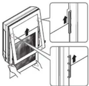

natural_image
Illustration of a hand inserting a small object into a device (no text or symbols visible)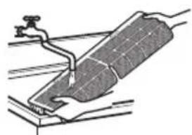
natural_image
Diagram of a solar panel installation with a water tap and pipe (no text or symbols)natural_image
Technical line drawing of a mechanical component with two upward arrows indicating force or movement (no text or symbols)30\~36 kBtu/h
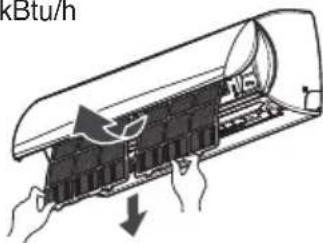
FILTRY POWIETRZA
natural_image
Line drawing of a mechanical device with a handle and internal components (no text or symbols)NOTĂ
natural_image
Line drawing of a mobile phone with keypad and control panel (no text or symbols)Vânt indirect (Oțional)
Vânt direct (Oțional)
Mod inteligent (Oțional)
natural_image
Pure electrical circuit lines without any symbolsAuto-curățare (Optional)
natural_image
Diagram of a device with a highlighted component and a pointing arrow (no text or symbols)Buton pornit / oprit
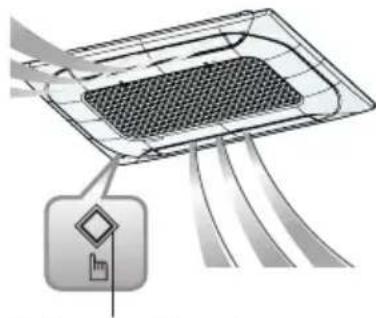
natural_image
Diagram of a device with a grid pattern and directional arrows, no text or symbols presentButon pornit / oprit
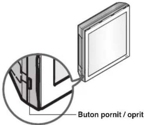
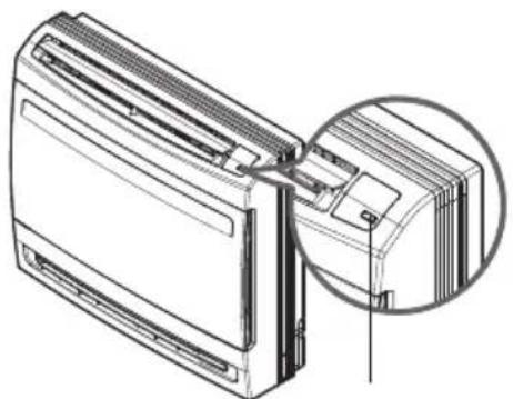
natural_image
Technical line drawing of a front-mounted air conditioner unit with a magnified inset showing internal components (no text or symbols)
natural_image
Technical line drawing of a mechanical device with a hand operating the component (no text or symbols present)natural_image
Diagram of hands operating a device with an arrow indicating direction (no text or symbols present)natural_image
Hand operating a mechanical device with a magnified inset showing internal components (no text or symbols visible)natural_image
Technical line drawing of a mechanical assembly with a hand holding a component (no text or symbols present)natural_image
Line drawing of a hand holding a mechanical component, no text or symbols presentnatural_image
Line drawing of a hand using a tool to cut or mark a mechanical component (no text or symbols present)natural_image
Diagram of a kitchen sink with two circular objects and a magnified inset showing a finger pointing to a textured surface (no text or symbols)natural_image
Technical diagram showing a mechanical component with cross-sectional views and internal structure (no text or symbols)natural_image
Technical line drawings of a heat exchanger panel with handle, cover plate, and tray (no text or symbols)natural_image
Illustration of hands performing a medical or therapeutic procedure on a device (no text or symbols present)natural_image
Line drawing of a hand inserting a switch into an electrical outlet (no text or symbols)natural_image
Diagram of a device with ports and connectors, showing internal components and directional arrows (no text or symbols)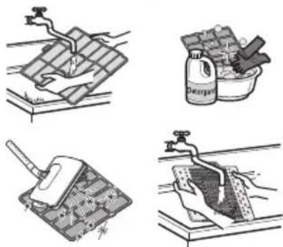
natural_image
Four-panel illustration showing different methods of cleaning or cleaning a surface: solar panel, spray bottle, mortar, and drain (no text or symbols)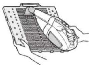
natural_image
Illustration of hands using a tool to handle a grid-patterned device (no text or symbols visible)natural_image
Illustration of a hand holding a rectangular panel with a clip, no text or symbols presentnatural_image
Illustration of hands installing or adjusting a mechanical component with arrows indicating motion (no text or symbols)natural_image
Illustration of hands interacting with a screen or tablet device (no text or symbols visible)- Scoateți imaginea.
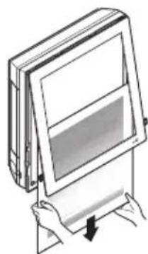
natural_image
Illustration of hands holding a rectangular device with a screen, showing a downward arrow (no text or symbols)natural_image
Illustration of hands holding a tablet with a magnified view of the screen (no text or symbols)natural_image
Illustration of hands inserting a component into a device (no text or symbols visible)natural_image
Technical line drawing of a car air duct or duct with internal grid pattern (no text or symbols)30\~36 kBtu/h

natural_image
Diagram of a car air conditioner unit with airflow arrows indicating airflow direction (no text or symbols)natural_image
Illustration of three different household cleaning methods: a water tap, a spray can on a surface, and a detergent bottle filled with granular material (no text or symbols)natural_image
Three-step diagram showing a device transitioning from closed to open air gap, with arrows indicating motion direction (no text or symbols)Scoaterea filtrelor
natural_image
Diagram showing airflow or ventilation system transformation from a fan-shaped device to a grid-patterned panel (no text or symbols)Eco design requirement
- The information for Eco design is available on the following free access website. https://www.lg.com/global/support/cedoc/cedoc