EC82 - Microphone AKG - Free user manual and instructions
Find the device manual for free EC82 AKG in PDF.
User questions about EC82 AKG
0 question about this device. Answer the ones you know or ask your own.
Ask a new question about this device
Download the instructions for your Microphone in PDF format for free! Find your manual EC82 - AKG and take your electronic device back in hand. On this page are published all the documents necessary for the use of your device. EC82 by AKG.
USER MANUAL EC82 AKG
natural_image
Illustration of four different feather illustrations in beige, brown, maroon, and black (no text or symbols)MICROLITE
WEARABLE MICROPHONES
LOW-PROFILE, ULTRA-MINIATURE MICROPHONES FOR THEATER, BROADCAST AND CONFERENCES
Read the manual before using the equipment!
102 MODE D'EMPLOI
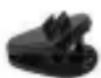
Abb. 6: H3
Kabelclip
natural_image
Black and blue compact device labeled 'AKG' with a zipper (no additional text or symbols visible)natural_image
Blue cable or cable with a magnified inset showing a small circular component (no text or symbols)natural_image
Two identical cylindrical electronic components with leads, shown in isometric view (no text or symbols)Abb. 13: Make-Up Schutz anbringen
natural_image
Black and blue compact device labeled 'AKG' with a zipper (no additional text or symbols visible)natural_image
Line drawing of two hands holding a tool, one with a blue arrow and the other with a diagonal line (no text or symbols)7
natural_image
Line drawing of a human head with a medical instrument inserted, showing anatomical positioning (no text or symbols)8
natural_image
Two cylindrical electronic components with leads, shown in line style (no text or symbols)natural_image
Black and blue hard drive case with 'ARG' label, no visible text or symbols beyond brandingnatural_image
Line drawing of a human head with surgical instrument placement (no text or symbols)natural_image
Simple line drawing of a blue cable or cable with a circular base and a small circular head (no text or symbols)10
natural_image
Illustration of a medical or laboratory probe with a blue clip attached to a cylindrical component (no text or symbols visible)natural_image
Pure electrical connector diagram without any text or symbolsnatural_image
Illustration of a medical or laboratory probe with a blue cable inserted into a cylindrical component (no text or symbols visible)natural_image
Illustration of a medical or laboratory device with a blue cable inserted into a cylindrical component (no text or symbols visible)natural_image
Illustration of a medical or laboratory device with a blue clip attached to a cylindrical component (no text or symbols visible)natural_image
Illustration of a medical device with a needle inserted, showing internal components (no text or symbols)natural_image
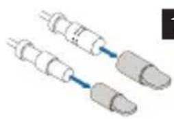
Six metallic cylindrical connectors with black caps and metallic bodies, shown from different angles (no text or symbols visible)MDA2 SEN1 MDA3 SEN2 MDA4 SHU MDA5 AT MDA6 BD MDA7 LEC
Abb. 39: Microdot-Adapter
natural_image
Black cylindrical electronic component with three pins (no text or symbols visible)Abb. 40: Phantomspeiseadapter (MDPA)
text_image
JPhase180 JumperAbb. 41: Phantomspeiseadapter
natural_image
Line drawing of a person playing a string instrument on a stool, with no text or symbols present.8.3.3 Theater, Musical, Oper
Theater, Musical, Oper

natural_image
Line drawing of a person with spiky hair and raised hand, no text or symbols presentnatural_image
Line drawing of a person playing violin (no text or symbols)natural_image
Simple line drawing of a medical or laboratory device with a loop and rod, no text or symbols present.1
natural_image
Diagram of a medical or surgical device with two curved components and directional arrows, no text or symbols present.natural_image
Medical catheter device with two tubes and a wire, no visible text or labels3
natural_image
Two mechanical components with blue arrows indicating direction, no visible text or symbolsnatural_image
Diagram of two electrical components with leads, connected by a blue arrow (no text or symbols)1
natural_image
Two cylindrical electronic components with leads, shown in wire and cap (no text or symbols visible)1
Frequenz-gang XX81 MD
10.1.1 Frequenzgang

line
| Ω | 1 m | 2 cm | 190° | | ---- | ----- | ----- | ----- | | 20 | -25 | -5 | -30 | | 60 | -20 | -5 | -30 | | 100 | -15 | -5 | -30 | | 200 | -10 | -5 | -30 | | 500 | -5 | -5 | -25 | | 1000 | 0 | -5 | -20 | | 2000 | 0 | -5 | -15 | | 5000 | 0 | -5 | -10 | | 10000| 0 | -5 | -5 | | 15000| 0 | 5 | -5 | | 20000| -5 | -5 | -10 |Abb. 46: Frequenzgang XX81 MD
Polar- diagramm XX81 MD
10.1.2 Polardiagramm
radar
| Angle | Frequency (Hz) | |-------|----------------| | 0° | 2000 | | 30° | 4000 | | 60° | 8000 | | 90° | 16000 | | 120° | 2500 | | 150° | 4000 | | 180° | 8000 |Abb. 47: Polardiagramm XX81 MD
Frequenz-gang XX82 MD
10.2.1 Frequenzgang

line
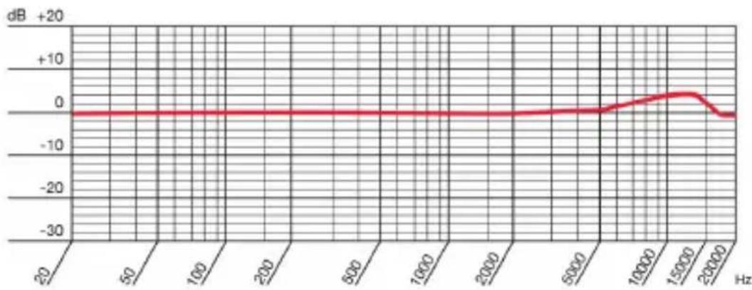
| Hz | dB | |-------|------| | 20 | 0 | | 50 | 0 | | 100 | 0 | | 200 | 0 | | 500 | 0 | | 1000 | 0 | | 2000 | 0 | | 5000 | 0 | | 10000 | 0 | | 15000 | 0 | | 20000 | -5 |Abb. 48: Frequenzgang XX82 MD
Polar- diagramm XX82 MD
10.2.2 Polardiagramm
radar
| Frequency Range | Value | | --------------- | ----- | | 125 Hz | -20 | | 250 Hz | -10 | | 500 Hz | -5 | | 600 Hz | 0 | | 800 Hz | 5 | | 1000 Hz | 10 |Abb. 49: Polardiagramm XX82 MD
1.1 Purpose of this user instructions 56
1.2 Storing this user instructions 56
1.3 Explanation of the symbols used 56
1.4 Correct use 57
1.5 Liability and warranty 57
1.6 Risk of damage 57
1.7 Safety and environment 58
1.7.1 Safety 58
1.8 Environment 59
2 DECLARATION OF CONFORMITY 59
3 MICROLITE: GENERAL DESCRIPTION 60
3.1 Introduction 60
3.2 Brief Description 60
3.3 MicroLite series variants 60
4 LAVALIER MICROPHONES 61
4.1 Package content 62
4.2 Accessories 63
4.2.1 Wire-mesh grill 63
4.2.2 Lavalier clips 64
4.2.3 Wind screen 64
4.2.4 Make-up cover 65
4.2.5 AKG adapter plug 65
4.2.6 Case with window 65
4.3 Attaching the lavalier microphone 66
4.3.1 Attaching the make-up cover 67
4.4 Using the microphone 68
4.5 Cleaning the microphone 68
5 EAR HOOK MICROPHONE 69
5.1 Package content 70
5.2 Accessories 70
5.2.1 Wire-mesh grill 71
5.2.2 Cable clip 71
5.2.3 Wind screen 71
5.2.4 Make-up cover 72
5.2.5 Protection against sweat 72
5.2.6 AKG adapter plug 73
5.2.7 Case with window 73
5.3 Attaching the ear hook microphone 74
5.3.1 Attaching the make-up cover 76
5.4 Using the microphone 76
5.5 Cleaning the microphone 76
6 HEADWORN MICROPHONES 77
6.1 Package content 78
6.2 Accessories 78
6.2.1 Wire-mesh grill 79
6.2.2 Cable clip 79
6.2.3 Wind screen 79
6.2.4 Make-up cover 80
6.2.5 Protection against sweat 80
6.2.6 AKG adapter plug 81
6.2.7 Case with window 81
6.3 Attaching the headworn microphone 82
6.4 Using the Microphone 84
6.5 Cleaning the microphone 84
7 CONNECTING THE MICROPHONE 84
7.1 Connecting the microphone to an AKG wireless system 84
7.2 Connecting the microphone to an alternative wireless system84
7.3 Connection to conventional mixing console using a cable 85
7.4 Optional accessories 85
7.4.1 Adapter plug for alternative systems 85
7.4.2 Phantom power adapter 86
8 USE 87
8.1 General 87
8.2 Tips for use 87
8.2.1 Positioning the microphone 87
8.2.2 Avoiding disturbances from electrical interference 87
8.2.3 Rotating the phase 88
8.3 Using a lavalier microphone 89
8.3.1 Voice transmission 89
8.3.2 Recording microphone or spot microphone 90
8.3.3 Theater, musical or opera 90
8.3.4 Recording musical instruments 91
8.4 Ear hook microphone and headworn microphone 92
8.4.1 Transmitting voices or songs 92
8.4.2 Recording musical instruments 92
9 CLEANING 93
9.1 Microphone 93
9.2 Ear clip 93
9.3 Protective cap 94
9.4 Wind screen 95
9.5 Make-up cover 95
10 TECHNICAL DATA 96
10.1 XX81 MD 96
10.1.1 Frequency response 96
10.1.2 Polar pattern 96
10.1.3 Specifications 97
10.2 XX82 MD 98
10.2.1 Frequency response 98
10.2.2 Polar pattern 98
10.2.3 Specifications 99
11 TROUBLESHOOTING 100
1 General
Purpose of this 1.1 Purpose of this user instructions
user instructions
This user instructions is intended to enable you to:
- Operate the equipment safely
- Use the equipment correctly.
Storing this user instructions
1.2 Storing this user instructions
Keep this user instructions in a safe place or store it electronically in an easily accessible location.
Pass this user instructions on to subsequent owners.
This user instructions is an important part of the equipment.
Symbols used 1.3 Explanation of the symbols used

Describes useful information and application notes for efficient operation of the equipment

Provides reference to more in-depth information and downloads online.
Includes information on the correct disposal of the components described.

Describes instructions on how to dispose of packaging correctly.
1.4 Correct use
Correct use
The microphones from the MicroLite series are designed exclusively for the transmission of sounds and voices.
1.5 Liability and warranty
Liability and warranty
AKG Acoustics GmbH accepts no liability or warranty for damage, if
- Microphones from the MicroLite series are used for purposes other than those described as intended use
- Damage is incurred due to incorrect operation
- Modifications are made to the microphones
- Documents are not kept up-to-date.
1.6 Risk of damage

Make sure that the piece of equipment your microphone will be connected to fulfills the safety regulations implemented in your country and is fitted with a ground lead.
1.7 Safety and environment
Safety
1.7.1 Safety
- Protect the equipment against
- Direct sunlight
- The impact of significant dust and humidity
- Rain
- Vibrations or knocks.
- Do not spill liquids on the equipment.
- The equipment must only be used in dry rooms.
- The equipment must only be opened, serviced and repaired by authorized personnel. The housing contains no user-serviceable parts.
- Do not place the equipment near heat sources such as radiators, heating ducts, amplifiers, etc.
- Do not expose the equipment to extreme forces and do not pull on the cable.
- Only use the equipment for the applications described in this user instructions. AKG cannot accept any liability for damages resulting from improper handling or misuse.
1.8 Environment
- At the end of the product's service life, disconnect the housing, electronics and cable from each other and discard all components in accordance with applicable disposal regulations.
- The packaging is recyclable. Dispose of the packaging via an appropriate collection system provided for this purpose.

2 Declaration of Conformity
This product conforms to the standards listed in the Declaration of Conformity. You can request the Declaration Of Conformity by E-Mail from sales@akg.com or download it from www.akg.com.
3 MicroLite: General description
Introduction
3.1 Introduction
Thank you for deciding to buy an AKG product. Read the user instructions carefully before using the equipment and keep the user instructions in a safe place so that you can refer to it at any time in the future. We hope you enjoy the equipment and good luck!
Brief description
3.2 Brief Description
The microphones from the MicroLite series are professional cardioid or omnidirectional condenser microphones. The microphones are specifically designed for use in the following high end areas:
- Musicals
- Theater
- TV shows
- Presentations
The compact size ensures optimum comfort. Additionally, the microphones feature the best sound quality and long service life.
The AKG MicroLite series is compatible with all common wireless systems and can connect to an XLR cable.
Versions
3.3 MicroLite series variants
The following variants, each being cardioid and omnidirectional, are available within the MicroLite series:
• Lavalier microphones (see pages 61 ff.)
- Ear hook microphones (see pages 69 ff.)
• Headworn microphones (see pages 77 ff.)
4 Lavalier microphones
The LC81 MD lavalier microphones are cardioid condenser microphones and are available in black, white, beige and cocoa.
LC81 MD
The LC82 MD lavalier microphones are omnidirectional condenser microphones and are available in black, white, beige and cocoa.
LC82 MD
The lavalier microphones in black and white are designed to be attached to clothing and have a 1 m cable.
The lavalier microphones in beige and cocoa are designed to be used with make-up in the head area and have a 1.3 m cable.
The corresponding clips for each of these microphones are included in the package content.
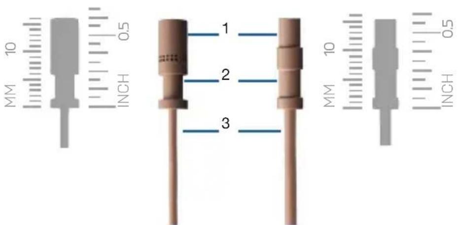
text_image
10 MM INCH 0.5 1 2 3 10 MM INCH 0.5Fig. 1: LC81 MD (left) and LC82 MD (right)
1 Microphone capsule
2 Recess for clip clasp (H1 and H2)
3 Microphone cable
4.1 Package content
Lavalier microphone package content
Check to ensure that the package contains all parts specified below.
All accessory parts necessary for use with AKG wireless systems are enclosed. Adapter plugs for other wireless systems can be found on page 85.
The microphones in the MicroLite series are condenser microphones. As a result, they require a power supply. The corresponding power adapter with phantom power is available as an optional accessory.
For more information, see pages 85 ff.
Optional accessories can be purchased later as required.
Microphone
- 1x LC81 MD (lavalier cardioid condenser microphone in black, white, beige or cocoa)
- 1x LC82 MD (lavalier omnidirectional condenser microphone in black, white, beige or cocoa)
4.2 Accessories
| LC81 MD LC82 MD black/white | LC81 MD LC82 MD black/white | |
| Microphone including cable 1 1 | ||
| MDA1 Microdot Adapter AKG 1 1 | ||
| WM81/WM82 Wire-mesh grill 2 2 | ||
| W81/W82 Foam wind screen 3 3 | ||
| MUP81/MUP82 Make-up cover 3 3 | ||
| H1 Magnet clip 1 | ||
| H2 Crocodile clip 1 | ||
| H3 Cable clip 1 1 | ||
| Transport case with window 1 1 |
LC81 MD LC82 MD accessories
4.2.1 Wire-mesh grill
Wire-mesh grill
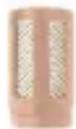
Fig. 2: WM81
Wire-mesh grill for LC81 MD
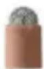
Fig. 3: WM82
Wire-mesh grill for LC82 MD
The supplied wire-mesh grill (WM81, WM82) consists of several layers of different materials.
The wire-mesh grill is used as protection against dirt and make-up. Additionally, the wire-mesh grill protects the microphone membrane from wind and pop noise.
Lavalier clips 4.2.2 Lavalier clips
The MicroLite series offers three different lavalier clips for attaching the microphone to clothing:

Fig. 4: H1 Magnet clip

Fig. 5: H2 Crocodile clip
Fig. 6: H3 Cable clip
The microphone is attached to the housing by the clasp on the clip: This helps ensure the microphone cable is protected.
The cable clip is used to fasten the cable to the article of clothing. The cable clip is used for the strain relief of the microphone cable.
Wind screen 4.2.3 Wind screen
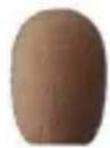
Fig. 7: W81
Wind screen for LC81 MD
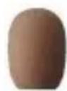
Fig. 8: W82 Wind screen for LC82 MD
The wind screen (W81, W82) is placed over the wire-mesh grill to shield the microphone from picking up wind outdoors. This ensures the sound is clean and the microphone is optimally protected.
4.2.4 Make-up cover
Make-up cover
Fig. 9: MUP81
Make-up cover for LC81 MD
Fig. 10: MUP82
Make-up cover for LC82 MD
The make-up cover (MUP81, MUP82) is placed on the microphone to protect it during the make-up application process.
4.2.5 AKG adapter plug
AKG adapter plug
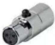
Fig. 11: MDA1 AKG adapter plug
The supplied MDA1 AKG adapter plug connects the MicroLite series microphone to the AKG bodypack transmitter with a 3-pin Mini-XLR input.
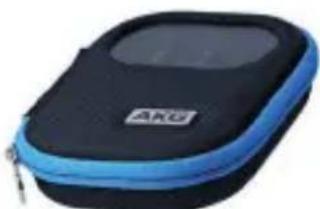
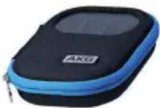
4.2.6 Case with window
Case
natural_image
Black and blue ARU device case with a zipper, no visible text or symbols on the body.Fig. 12: Case with window
The supplied case is used as a secure way of storing the lavalier microphone. The built-in window enables you to check the color or type of microphone at any time without having to open the case.
Attaching the lavalier microphone
4.3 Attaching the lavalier microphone

text_image
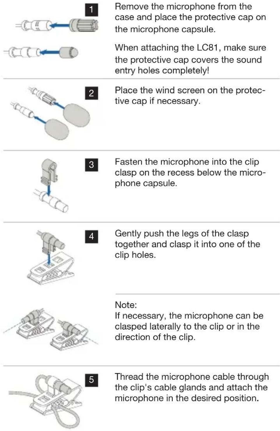
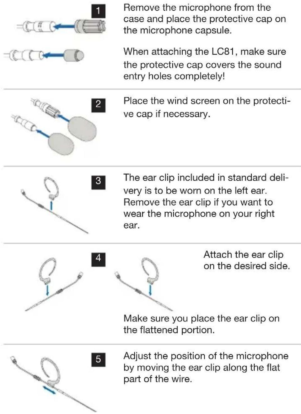
1 Remove the microphone from the case and place the protective cap on the microphone capsule. When attaching the LC81, make sure the protective cap covers the sound entry holes completely! 2 Place the wind screen on the protective cap if necessary. 3 Fasten the microphone into the clip clasp on the recess below the microphone capsule. 4 Gently push the legs of the clasp together and clasp it into one of the clip holes. Note: If necessary, the microphone can be clasped laterally to the clip or in the direction of the clip. 5 Thread the microphone cable through the clip's cable glands and attach the microphone in the desired position.
natural_image
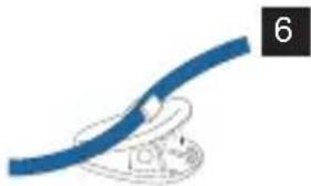
Blue cable or cable with a magnified inset showing a small circular component (no text or symbols)To support the cable, use the H3 cable clip (provided in the LCXX MD package content, available in beige or cocoa):
Press the cable into the cable clip and attach the clip to the article of clothing.
7 Connect the microphone. For more information, see pages 84 ff.
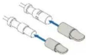
4.3.1 Attaching the make-up cover
natural_image
Two identical cylindrical electronic components with leads, shown in isometric view (no text or symbols)Fig. 13: Attaching the make-up cover

Fig. 14: Lavalier microphone with make-up cover during make-up application
If the microphone is built into the mask, place the make-up cover directly on the microphone capsule during the make-up application process!
Place the protective cap back on after removing the make-up cover! If necessary, the wind screen can be placed over the protective cap.

4.4 Using the microphone
For details on use, see from page 87 ff.
4.5 Cleaning the microphone
For details on cleaning the individual parts, see from page 93 ff.
5 Ear hook microphone
The EC81 MD ear hook microphones are cardioid condenser microphones and are available in beige and cocoa.
EC81 MD
The EC82 MD ear hook microphones are omnidirectional condenser microphones and are available in beige and cocoa.
EC82 MD
text_image
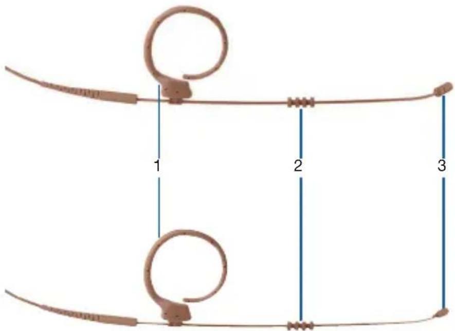
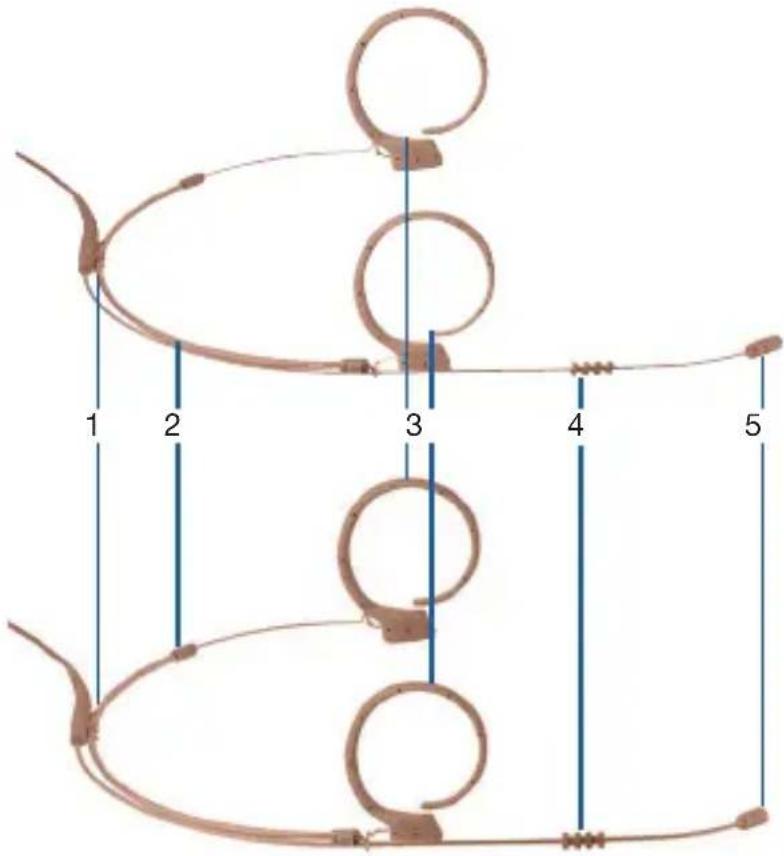
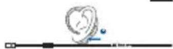
1 2 3Fig. 15: EC81 MD (top) and EC82 MD (bottom)
1 Ear clip
2 Moisture shield
3 Microphone capsule
5.1 Package content
Ear hook microphone package content
Check to ensure that the package contains all parts specified below.
All accessory parts necessary for use with AKG wireless systems are enclosed. Adapter plugs for other wireless systems can be found on page 85.
The microphones in the MicroLite series are condenser microphones. As a result, they require a power supply. The corresponding power adapter with phantom power is available as an optional accessory.
For more information, see pages 85 ff.
Optional accessories can be purchased later as required.
Microphone
- 1x EC81 MD (ear hook cardioid condenser microphone in beige or cocoa)
- 1x EC82 MD (ear hook omnidirectional condenser microphone in beige or cocoa)
5.2 Accessories
| EC81 MD beige/cocoa | EC82 MD beige/cocoa | ||
| EC81 MDEC82 MDaccessories | Microphone including cable 1 1 | ||
| MDA1 Microdot Adapter AKG 1 1 | |||
| WM81/WM82 Wire-mesh grill 2 2 | |||
| W81/W82 Foam wind screen 3 3 | |||
| MUP81/MUP82 Make-up cover 3 3 | |||
| H3 Cable clip 1 1 | |||
| Transport case with window 1 1 |
5.2.1 Wire-mesh grill
Wire-mesh grill

Fig. 16: WM81 Wire-mesh grill for EC81 MD

Fig. 17: WM82 Wire-mesh grill for EC82 MD
The supplied wire-mesh grill (WM81, WM82) consists of several layers of different materials.
The wire-mesh grill is used as protection against dirt and make-up. Additionally, the wire-mesh grill protects the microphone membrane from wind and pop noise.
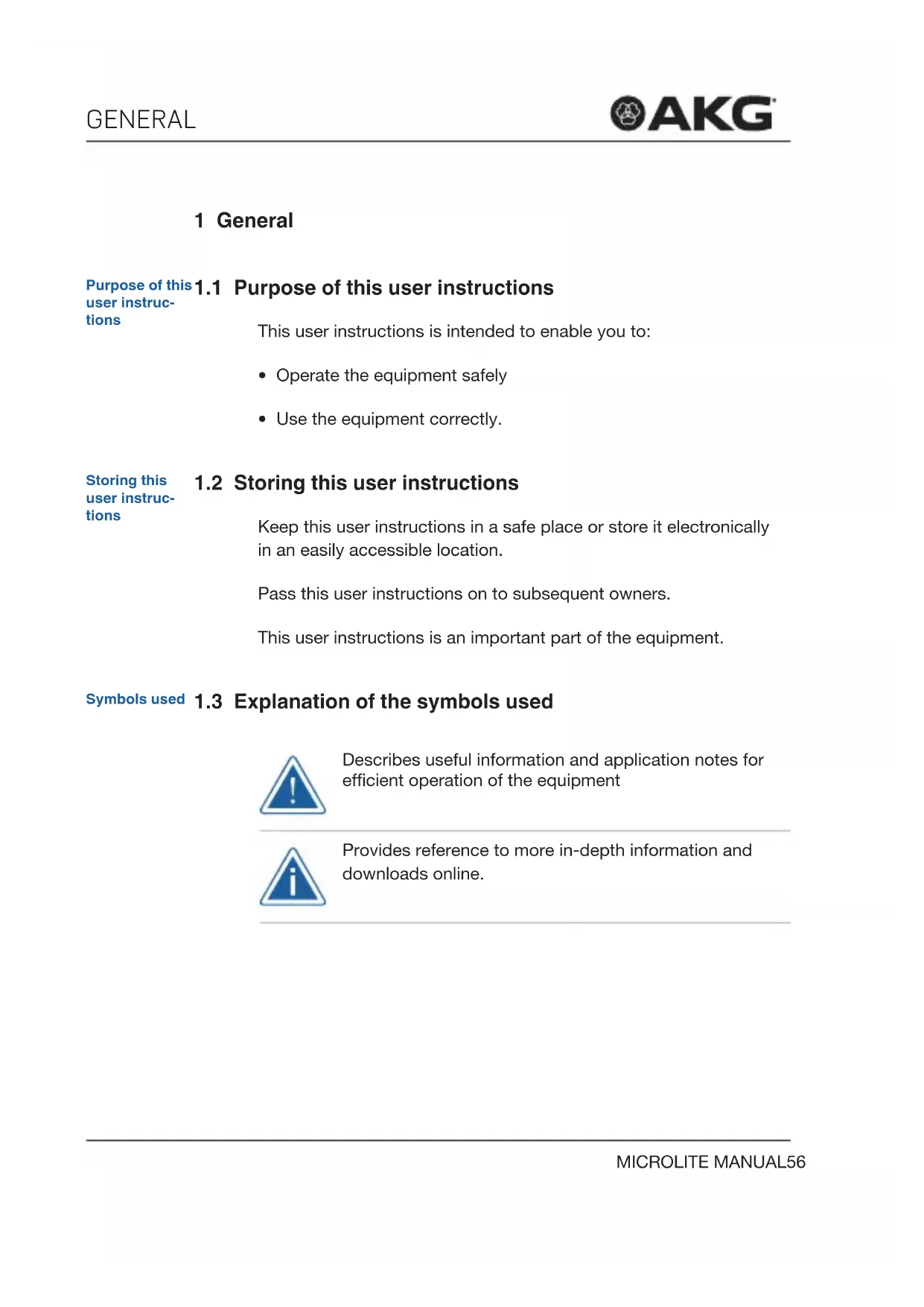
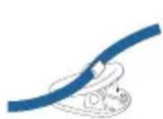
5.2.2 Cable clip
Cable clip
The cable clip is used to fasten the cable to the article of clothing, which relieves stress on the microphone cable.
Fig. 18: H3 Cable clip
The microphone is attached to the housing by the clasp on the clip: This helps ensure the microphone cable is protected.
5.2.3 Wind screen
Wind screen
Fig. 19: W81
Wind screen for EC81 MD
Fig. 20: W82 Wind screen for EC82 MD
The wind screen (W81, W82) is placed over the wire-mesh grill to shield the microphone from picking up wind outdoors. This ensures the sound is clean and the microphone is optimally protected.
Make-up cover
5.2.4 Make-up cover

Fig. 21: MUP81
Make-up cover for EC81 MD

Fig. 22: MUP82
Make-up cover for EC82 MD
The make-up cover (MUP81, MUP82) is placed on the microphone to protect it during the make-up application process.
Protection against sweat
5.2.5 Protection against sweat

Fig. 23: Moisture shield
The ear hook microphones are equipped with a patented moisture shield that is attached to the wire frame.
The moisture shield prevents sweat and make-up from penetrating into the capsule area.
This prevents the microphone from being blocked, which could lead to dull sound and lower microphone sensitivity.
5.2.6 AKG adapter plug
AKG adapter plug
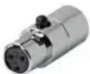
Fig. 24: MDA1 AKG adapter plug
The supplied MDA1 AKG adapter plug connects the MicroLite series microphone to the AKG bodypack transmitter with a 3-pin Mini-XLR input.
5.2.7 Case with window
Case

natural_image
Black and blue compact device labeled 'AKG' with a zipper (no additional text or symbols visible)Fig. 25: Case with window
The supplied case is used as a secure way of storing the lavalier microphone. The built-in window enables you to check the color or type of microphone at any time without having to open the case.
Attaching the ear hook microphone
5.3 Attaching the ear hook microphone

Remove the microphone from the case and place the protective cap on the microphone capsule.
When attaching the LC81, make sure the protective cap covers the sound entry holes completely!
Place the wind screen on the protective cap if necessary.
3 The ear clip included in standard delivery is to be worn on the left ear. Remove the ear clip if you want to wear the microphone on your right ear.
Attach the ear clip on the desired side.
Make sure you place the ear clip on the flattened portion.
5 Adjust the position of the microphone by moving the ear clip along the flat part of the wire.

6
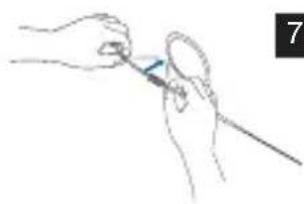
Place the ear clip over your ear so that the ear clip's amplifier fits snugly behind your earlobe.
natural_image
Line drawing of two hands holding a tool, one with a blue tool and the other with a white tool (no text or symbols)7
If the microphone is too loose, remove the microphone again and carefully bend the wire frame inwards.
natural_image
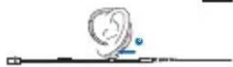
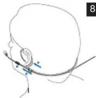
Line drawing of a human head with a medical instrument inserted, showing anatomical positioning (no text or symbols)8
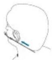
Position the microphone so that the microphone capsule is approximately 1 cm away from the corner of your mouth (1).
Make sure the piece intended to protect against sweat is positioned against the skin and not against the wire frame (2).
9
Make sure the ear clip's amplifier fits snugly behind your earlobe (3).
If necessary, attach the wire frame to your cheek using a piece of tape.
10
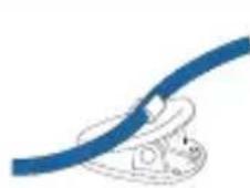
Use the supplied H3 cable clip as a strain relief:
Press the cable into the cable clip and attach the clip to the article of clothing.
11
Connect the microphone. For more information, see from page 84 ff.
Attaching the make-up cover
5.3.1 Attaching the make-up cover
natural_image
Two cylindrical electronic components with leads, no visible text or symbolsFig. 26: Attaching the make-up cover
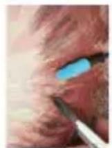
Fig. 27: Microphone with make-up cover during make-up application

If the microphone is built into the mask, place the make-up cover directly on the microphone capsule during the make-up application process!
Place the protective cap back on after removing the make-up cover! If necessary, the wind screen can be placed over the protective cap.
Use
5.4 Using the microphone
For details on use, see from page 87 ff.
Cleaning
5.5 Cleaning the microphone
For details on cleaning the individual parts, see from page 93 ff.
6 Headworn microphones
The HC81 MD headworn microphones are cardioid condenser microphones and are available in beige and cocoa.
HC81 MD
The HC82 MD headworn microphones are omnidirectional condenser microphones and are available in beige and cocoa.
HC82 MD
text_image
1 2 3 4 5Fig. 28: HC81 MD (top) and HC82 MD (bottom)
1 Strain relief for microphone cable
4 Moisture shield
2 Headset 5 Microphone capsule
3 Ear clip
6.1 Package content
Headworn microphone package content
Check to ensure that the package contains all parts specified below.
All accessory parts necessary for use with AKG wireless systems are enclosed. Adapter plugs for other wireless systems can be found on page 85.
The microphones in the MicroLite series are condenser microphones. As a result, they require a power supply. The corresponding power adapter with phantom power is available as an optional accessory.
For more information, see pages 85 ff.
Optional accessories can be purchased later as required.
Microphone
- 1x HC81 MD (headworn cardioid condenser microphone in beige or cocoa)
- 1x HC82 MD (headworn omnidirectional condenser microphone in beige or cocoa)
6.2 Accessories
| HC81 MD beige/cocoa | HC82 MD beige/cocoa | ||
| HC81 MD HC82 MD accessories | Microphone including cable 1 1 | ||
| MDA1 Microdot Adapter AKG 1 1 | |||
| WM81/WM82 Wire-mesh grill 2 2 | |||
| W81/W82 Foam wind screen 3 3 | |||
| MUP81/MUP82 Make-up cover 3 3 | |||
| H3 Cable clip 1 1 | |||
| Transport case with window 1 1 |
6.2.1 Wire-mesh grill
Wire-mesh grill
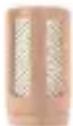
Fig. 29: WM81 Wire-mesh grill for EC81 MD

Fig. 30: WM82 Wire-mesh grill for EC82 MD
The supplied wire-mesh grill (WM81, WM82) consists of several layers of different materials.
The wire-mesh grill is used as protection against dirt and make-up. Additionally, the wire-mesh grill protects the microphone membrane from wind and pop noise.
6.2.2 Cable clip
Cable clip
The cable clip is used to fasten the cable to the article of clothing, which relieves stress on the microphone cable.
Fig. 31: H3 Cable clip
The microphone is attached to the housing by the clasp on the clip: This helps ensure the microphone cable is protected.
6.2.3 Wind screen
Wind screen
Fig. 32: W81
Wind screen for EC81 MD

Fig. 33: W82
Wind screen for EC82 MD
The wind screen (W81, W82) is placed over the wire-mesh grill to shield the microphone from picking up wind outdoors. This ensures the sound is clean and the microphone is optimally protected.
Make-up cover 6.2.4 Make-up cover
Fig. 34: MUP81
Make-up cover for EC81 MD

Fig. 35: MUP82
Make-up cover for EC82 MD
The make-up cover (MUP81, MUP82) is placed on the microphone to protect it during the make-up application process.
Protection against sweat 6.2.5 Protection against sweat

Fig. 36: Moisture shield
The headworn microphones are equipped with a patented moisture shield that is attached to the wire frame.
The moisture shield prevents sweat and make-up from penetrating into the capsule area.
This prevents the microphone from being blocked, which could lead to dull sound and lower microphone sensitivity.
6.2.6 AKG adapter plug
AKG adapter plug

Fig. 37: MDA1 AKG adapter plug
The supplied MDA1 AKG adapter plug connects the MicroLite series microphone to the AKG bodypack transmitter with a 3-pin Mini-XLR input.
6.2.7 Case with window
Case
natural_image
Black and blue compact device labeled 'AKG' with a zipper (no additional text or symbols visible)Fig. 38: Case with window
The supplied case is used as a secure way of storing the lavalier microphone. The built-in window enables you to check the color or type of microphone at any time without having to open the case.
Attaching the headworn microphone
6.3 Attaching the headworn microphone

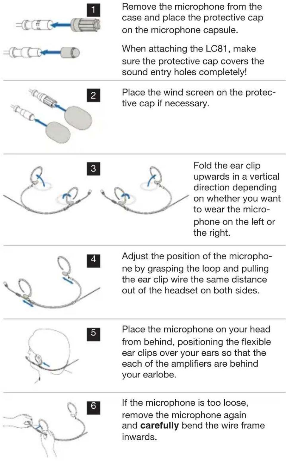
text_image
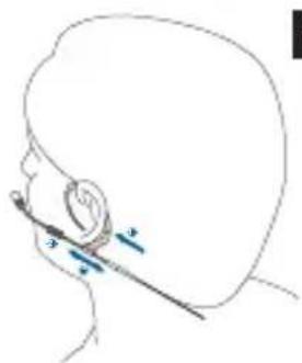
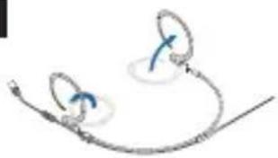
1 Remove the microphone from the case and place the protective cap on the microphone capsule. When attaching the LC81, make sure the protective cap covers the sound entry holes completely! 2 Place the wind screen on the protective cap if necessary. 3 Fold the ear clip upwards in a vertical direction depending on whether you want to wear the microphone on the left or the right. 4 Adjust the position of the microphone by grasping the loop and pulling the ear clip wire the same distance out of the headset on both sides. 5 Place the microphone on your head from behind, positioning the flexible ear clips over your ears so that the each of the amplifiers are behind your earlobe. 6 If the microphone is too loose, remove the microphone again and carefully bend the wire frame inwards.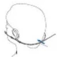
7
Place the microphone on your head again and adjust the headset by pushing the clip toward your neck from behind until it fits snugly.
natural_image
Line drawing of a human head with a medical instrument inserted, showing anatomical positioning (no text or symbols)8
Position the microphone so that the microphone capsule is approximately 1 cm away from the corner of your mouth (1).
Make sure the piece intended to protect against sweat is positioned against the skin and not against the wire frame (2).
9
Make sure the ear clip's amplifier fits snugly behind your earlobe (3).
If necessary, attach the wire frame to your cheek using a piece of tape.
We recommend using a mirror to check the correct position of the headworn microphone. Alternatively, a second person can help ensure the headworn microphone is in the correct position.
10
Use the supplied H3 cable clip as a strain relief:
Press the cable into the cable clip and attach the clip to the article of clothing.
11
Connect the microphone. For more information, see from page 84 ff.

6.4 Using the Microphone
For details on use, see from page 87 ff.
6.5 Cleaning the microphone
For details on cleaning the individual parts, see from page 93 ff.
Connection
7 Connecting the microphone
AKG wireless system
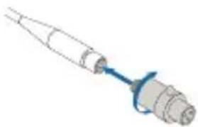
7.1 Connecting the microphone to an AKG wireless system
natural_image
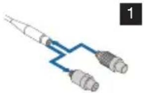
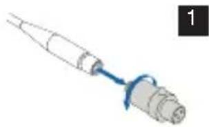
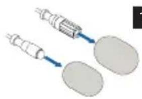
Pure diagram of a mechanical connector or probe assembly without any text, numbers, or symbolsScrew the supplied MDA1 AKG adapter plug into the Microdot plug to connect it to an AKG wireless system.
Alternative wireless systems
7.2 Connecting the microphone to an alternative wireless system

AKG makes no guarantee of compatibility to third-party wireless systems and assumes no liability in this respect!
For more information, refer to the user instructions from the respective wireless system manufacturer.
natural_image
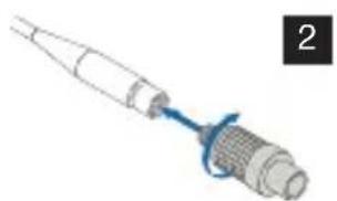
Pure electrical circuit lines without any symbolsReplace the AKG adapter plug with the corresponding adapter plug to connect it to an alternative wireless system.
natural_image
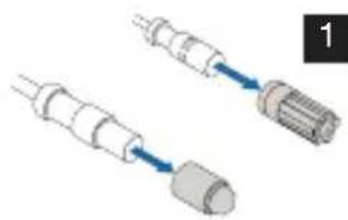
Illustration of a medical or laboratory probe with a blue ribbon, no text or symbols presentScrew on the corresponding adapter. (For more information, see from page 85 ff)
7.3 Connection to conventional mixing console using a cable
natural_image
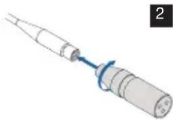
Illustration of a medical or laboratory device with a blue ribbon connecting its tip (no text or symbols)Replace the AKG adapter plug with the corresponding phantom power adapter (MDPA) to connect it to an alternative mixing console.
natural_image
Illustration of a medical or laboratory device with a blue cable and a pointed tip, no text or symbols present.Connect the phantom power adapter (MDPA) (for more information, see from page 85 ff).
The microphones in the MicroLite series are condenser microphones. As a result, they require a power supply.
natural_image
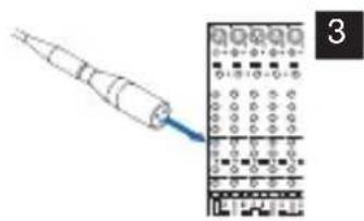
Illustration of a probe inserted into a grid device (no text or symbols visible)Connect the microphone to a balanced XLR microphone input with phantom power.
Connect the microphone input cable to the mixing console.

7.4 Optional accessories
7.4.1 Adapter plug for alternative systems
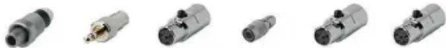
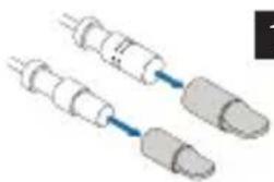
All MicroLite microphones are equipped with a cable and a Microdot plug: This ensures the microphones can be used with a wide variety of wireless systems (AKG ^® , Audio-Technica ^® , Beyerdynamic, Lectrosonics ^® , Sennheiser ^® and Shure ^® ). ^1
In addition to a wide variety of optional accessories, the corresponding adapters can be found on our website www.akg.com.
natural_image
Six metallic cylindrical connectors with black and white bodies, shown from different angles (no text or symbols visible)MDA2 SEN1 MDA3 SEN2 MDA4 SHU MDA5 AT MDA6 BD MDA7 LEC
Fig. 39: Microdot Adapter
AKG makes no guarantee of compatibility to third-party wireless systems and assumes no liability in this respect.
7.4.2 Phantom power adapter
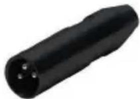
natural_image
Black cylindrical electronic component with three pins (no text or symbols visible)Fig. 40: Phantom power adapter (MDPA)
To ensure complete flexibility with the MicroLite microphone, users can switch to a wired application using the phantom power adapter.
The phantom adapter is equipped with:
- Microdot input
- XLR output
- Low cut filter (switchable)
- Phase rotation (can be plugged in via a jumper on the board, for more information, see page 88)

8 Use
Use
8.1 General
The major advantage of a microphone that is attached to an article of clothing, on the user's head or in their mask is that the distance between the microphone and the user's mouth is always the same.
This ensures there is no need to worry about the microphone level fluctuating.
The freedom of movement is preserved and hands remain free.
8.2 Tips for use
8.2.1 Positioning the microphone
Positioning the micro-phone
The following must be taken into consideration when positioning cardioid condenser microphones:
- The closer the microphone is positioned to the sound source, the more low frequencies are captured.
- Cardioid condenser microphones are sensitive to body noises and wind noises.
8.2.2 Avoiding disturbances from electrical interference
Avoiding interference
- To avoid hum or interference, route all audio lines, particularly those connected to the microphone inputs, away from power lines of any type.
- If you use cable ducts, be sure to use separate ducts for the audio lines.
8.2.3 Rotating the phase
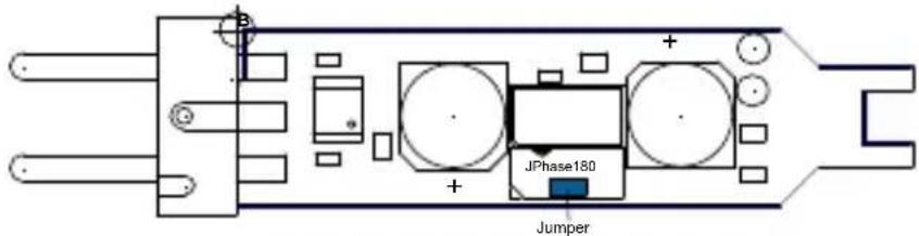
text_image
JPhase180 JumperFig. 41: Phantom power adapter
The signal phase can be rotated by 180^ using the phantom power adapter.
1) Screw the Phillips-head screw into the phantom adapter's housing.
2) Remove the housing.
3) Remove the jumper and plug it into only one pin.
4) Put the housing on.
5) Tighten the screws.
8.3 Using a lavalier microphone
8.3.1 Voice transmission
Voice transmission
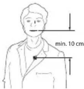
text_image
min. 10 cmFig. 42: Voice transmission
Fasten the microphone to a piece of clothing with the crocodile clip to ensure optimal voice transmission. Position the microphone as close as possible to the speaker's mouth.
The smaller the distance between the microphone and the sound source, the lower the risk of acoustic feedback and the less room noise will be picked up in the audio signal.

Recording microphone and spot microphone
8.3.2 Recording microphone or spot microphone
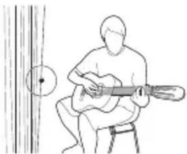
natural_image
Line drawing of a person playing an acoustic guitar on a stool, with no text or symbols present.Fig. 43: Microphone attached to a decorative piece
Fasten the microphone to a suitable decorative piece using the crocodile clip or the magnet clip (e.g. a backdrop, background or curtain).
Theater, musical or opera
8.3.3 Theater, musical or opera
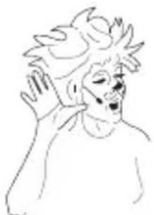
natural_image
Line drawing of a person with spiky hair and open mouth, no text or symbols presentFig. 44: Transmitting voices or songs
Attach the microphone in the mask as close as possible to the mouth.
8.3.4 Recording musical instruments
The microphone can be attached to a variety of different instruments (e.g. string instruments, guitars, wind instruments).
You only need to rotate the gain controller on the mixing console slightly because the microphone is located very close to the sound source.
For this reason, feedback occurs only in very low levels in PA systems.
Attach the microphone to different positions on the instrument and compare the sound to determine the optimal position of the microphone on an instrument.
You can use the supplied wind screen on wind instruments to dampen the sounds of rushing air.
Violin
Violin
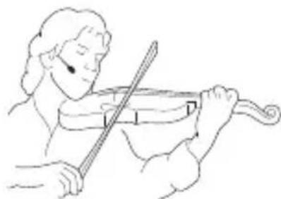
natural_image
Line drawing of a violinist playing a violin (no text or symbols)Fig. 45: Microphone for recording the violin
The microphone can be fastened to the performer's cheek using a piece of tape if the microphone cannot or should not be attached to the violin itself.
Alternatively, you can use the ear clip or the headworn microphone.
Recording musical instruments
This method offers the following advantages:
• The sound of the violin is not influenced.
- There is no risk of damaging the violin by using tape.
- The violin does not require a cable connection.
8.4 Ear hook microphone and headworn microphone
Voice transmission
8.4.1 Transmitting voices or songs
Attach the microphone as described in section 5 and 6.3.
Make sure that the microphone is approximately 1 cm away from the corner of your mouth.
Recording musical instruments
8.4.2 Recording musical instruments
Attach the microphone as described in section 5 and 6.3.
Make sure that the microphone is approximately 1 cm away from the corner of your mouth.
You can use the supplied wind screen on wind instruments to dampen the sounds of rushing air.
9 Cleaning
Clean the following parts before you store the microphone in the case:
- Microphone
- Ear clip
- Protective cap
- Wind screen
- Make-up cover
Stow the microphone in the case.
9.1 Microphone
Microphone
Use a damp cloth to clean the microphone housing.
Do not use any cleaning agents.
9.2 Ear clip
Ear clip
natural_image
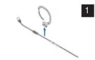
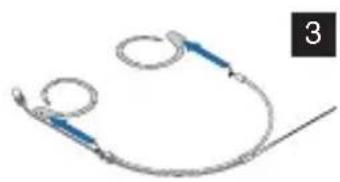
Simple line drawing of a medical or laboratory instrument with a loop and pointer (no text or symbols)Pull the ear clip from the wire on the ear hook microphone.
natural_image
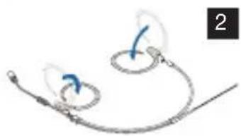
Diagram of a medical or surgical device with two curved components and directional arrows, no text or symbols present.Fold the ear clip vertically inward on the headworn microphone.
natural_image
Medical or medical device with two circular loops and a long wire, no visible text or symbolsPull the ear clip from the wire on the lower amplifier.
4 Wash the ear clip in hot, soapy water (60 to 70 °C).
Allow the ear clip to dry completely.
Push the ear clip back on to the wire.
Protective cap
9.3 Protective cap

natural_image
Two mechanical components with blue arrows indicating direction, no visible text or symbolsRemove the protective cap from the microphone.
2 Wash the protective cap in warm, soapy water.
Allow the protective cap to dry completely before using it again.
9.4 Wind screen
Wind screen
natural_image
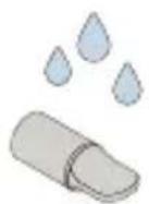
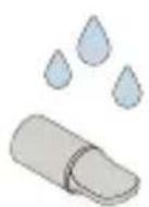
Illustration of two medical or surgical instruments with blue arrows pointing to their body (no text or symbols)Remove the wind screen from the microphone.
2 Wash the wind screen in warm, soapy water.
Allow the wind screen to dry completely before using it again.

9.5 Make-up cover
Make-up cover
natural_image
Two cylindrical electronic components with leads, shown in blue and gray (no text or symbols)Remove the make-up cover from the microphone.
2 Wash the make-up cover in warm, soapy water.
Allow the make-up cover to dry completely before using it again.

10 Technical data
XX81 MD
10.1 XX81 MD
XX81 MD frequency response
10.1.1 Frequency response
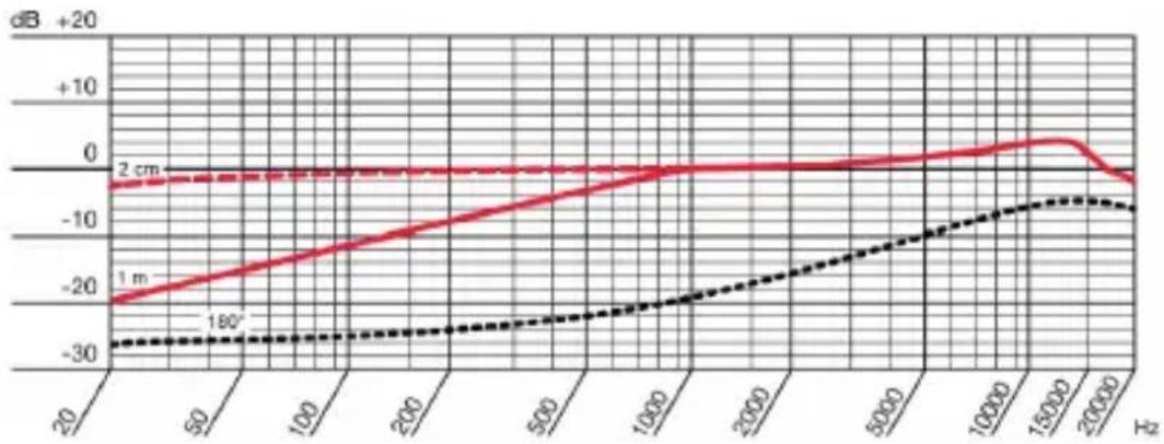
line
| N | 1 m | 2 cm | 190° | |------|-------|-------|-------| | 20 | -25 | -5 | -30 | | 60 | -20 | -5 | -30 | | 100 | -15 | -5 | -30 | | 200 | -10 | -5 | -30 | | 500 | -5 | -5 | -25 | | 1000 | 0 | -5 | -20 | | 2000 | 0 | -5 | -15 | | 5000 | 0 | -5 | -10 | | 10000| 0 | -5 | -5 | | 15000| 0 | 0 | 0 | | 20000| -5 | -5 | -5 |Fig. 46: XX81 MD frequency response
XX81 MD polar pattern
10.1.2 Polar pattern
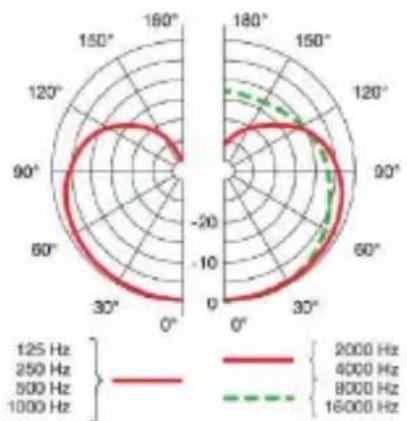
radar
| Angle | Frequency (Hz) | |-------|----------------| | 0° | 125 Hz | | 30° | 250 Hz | | 60° | 500 Hz | | 90° | 800 Hz | | 120° | 1000 Hz | | 150° | 125 Hz | | 180° | 250 Hz |Fig. 47: XX81 MD polar pattern
10.1.3 Specifications
XX81 MD specification
Capsule Capsule with condenser microphone
Directivity pattern Cardioid
Frequency range 20 to 20,000 Hz (2 - 3 cm)
Sensitivity 13 mV/Pa
Signal-to-noise ratio 57 dB(A)
Max. SPL 145 dB (sound pressure level)
THD (total harmonic distortion) at 1,000 Hz/120 dB <1%
Electric impedance at 5,000 ohms 1,000 Hz
Equivalent noise level 35.5 mV
Required voltage (typical 5 V at 4.5 kOhm, two-wire power requirement)
Dimensions Microphone (capsule):
∅ 4.4 mm
Length: 8.5 mm
Cable:
∅ 1.4 mm
Weight (including cable) LC: EC: HC: 5.3 g 7.6 g 11.7 g
Connection 1 Microdot
Connection 2 All common brands
XX82 MD
10.2 XX82 MD
XX82 MD frequency response
10.2.1 Frequency response
line
| Hz | dB | |-------|------| | 20 | 0 | | 50 | 0 | | 100 | 0 | | 200 | 0 | | 500 | 0 | | 1000 | 0 | | 2000 | 0 | | 5000 | 0 | | 10000 | 0 | | 15000 | 0 | | 20000 | -5 |Fig. 48: XX82 MD frequency response
XX82 MD polar pattern
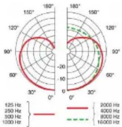
10.2.2 Polar pattern
radar
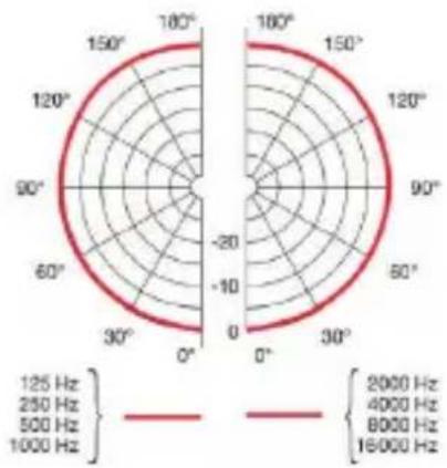
| Frequency Range | Value | | --------------- | --------- | | 2000 Hz | 2000 Hz | | 4000 Hz | 4000 Hz | | 8000 Hz | 8000 Hz | | 16000 Hz | 16000 Hz |Fig. 49: XX82 MD polar pattern
10.2.3 Specifications
XX82 MD specification
Capsule Capsule with condenser microphone
Directivity pattern Omnidirectional
Frequency range 20 to 20,000 Hz (2 - 3 cm)
Sensitivity 15 mV/Pa
Signal-to-noise ratio 63 dB(A)
Max. SPL 145 dB (sound pressure level)
THD (total harmonic distortion) at 1,000 Hz/120 dB <1%
Electric impedance at 5,000 ohms 1,000 Hz
Equivalent noise level 31.2 mV
Required voltage (typical 5 V at 4.5 kOhm, two-wire power requirement) requirement
Dimensions Microphone (capsule): ∅ 3.6 mm; Length: 7.2 mm
Cable: ∅ 1.4 mm
Weight (including cable) LC: 5.3 g EC: 7.6 g HC: 11.7 g
Connection 1 Microdot
Connection 2 All common brands
11 Troubleshooting
Problem Possible cause Remedy
| No sound Power to mixing console and/or amplifier is off | Switch on power to mixing console or amplifier |
| Channel fader or master level controller on the mixing console or volume control on amplifier is at zero | Set channel fader or master level controller on mixing console or volume control on amplifier to desired level |
| Microphone is not connected to mixing console or amplifier | Connect microphone to mixing console or amplifier |
| Cable connector not plugged in correctly | Plug in cable connector again |
| The cable is defective Check the cable and replace if necessary | |
| No supply voltage Switch on phantom power. | |
| Check the cable and replace if necessary | |
Problem Possible cause Remedy
| Distortions | Gain controller on the mixing console set too high | Turn gain controller down |
| Mixing console input sensitivity too high | Insert a preattenuation pad between the microphone cable and the input | |
| Canceling some frequencies | Shifting the phase The phase can be shifted by 180°For more information, see page 88 | |
In addition, read the user instructions of the transmitter and receiver!

1 GÉNÉRALITÉS 105
natural_image
Black and blue compact device labeled 'AKG' with a zipper (no additional text or symbols visible)natural_image
Simple blue curved line with a circular base and a small black square labeled '6' (no text or symbols on the line itself)natural_image
Illustration of two cylindrical electronic components with leads, no text or symbols presentProtection ma-quillage
Fig. 21 : MUP81
Protection maquillage EC81 MD
Fig. 22 : MUP82
Protection maquillage EC82 MD
natural_image
Black and blue compact device labeled 'AKG' with a zipper (no additional text or symbols visible)natural_image
Illustration of a hand holding a small object with a pen, no text or symbols present7
natural_image
Line drawing of a human head with a medical instrument inserted, showing anatomical positioning (no text or symbols)8
natural_image
Two cylindrical electronic components with leads, no visible text or symbolsProtection ma-6.2.4 Protection maquillage quillage
Fig. 34 : MUP81
Protection maquillage EC81 MD
Fig. 35 : MUP82
Protection maquillage EC82 MD
natural_image
Black and blue compact device labeled 'AKG' with a zipper (no additional text or symbols visible)natural_image
Two types of electrical connectors with blue wires, no text or symbols visiblenatural_image
Medical catheter device with two blue surgical instruments attached to a wire (no text or labels visible)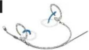
natural_image
Medical catheter device with two blue arrows indicating force or movement (no text or symbols)natural_image
Medical catheter or wire loop diagram with blue connectors and a white end cap (no text or labels)natural_image
Simple line drawing of a human head with a finger pointing to the ear area (no text or symbols)5
natural_image
Line drawing of hands holding a curved object with a looped end (no text or symbols)natural_image
Line drawing of a human head with medical instruments, no text or symbols presentnatural_image
Illustration of a medical or laboratory device with a blue connector (no text or symbols visible)natural_image
Pure electrical connector diagram without any text or symbolsnatural_image
Illustration of a medical or laboratory probe with a blue cable inserted into a cylindrical component (no text or symbols visible)natural_image
Illustration of a medical or laboratory device with a blue ribbon connecting its tip to a cylindrical component (no text or symbols visible)natural_image
Illustration of a medical or laboratory device with a blue clip attached to a cylindrical component (no text or symbols visible)Branchez l'adaptateur d'alimentation fantôme (MDPA) (Voyez page 136 ff).
natural_image
Illustration of a medical device with a needle inserted, showing internal components (no text or symbols)natural_image
Six metallic cylindrical connectors with black and gold contacts, shown from different angles (no text or symbols visible)MDA2 SEN1 MDA3 SEN2 MDA4 SHU MDA5 AT MDA6 BD MDA7 LEC
natural_image
Black cylindrical electronic component with three pins (no text or symbols visible)text_image
JPhase180 Jumpernatural_image
Line drawing of a person playing a stringed instrument on a stool, with no text or symbols present.natural_image
Line drawing of a person with spiky hair and expressive hand (no text or symbols)natural_image
Line drawing of a violinist playing a violin (no text or symbols)natural_image
Medical or laboratory probe setup with a loop and rod, no visible text or symbolsnatural_image
Diagram of a medical or surgical device with two circular components and directional arrows, no text or symbols presentnatural_image
Medical or laboratory device with coiled tubing and connectors (no visible text or symbols)natural_image
Two mechanical components with blue arrows indicating assembly or connection (no text or symbols)natural_image
Illustration of two medical or surgical instruments with blue arrows pointing to their body (no text or symbols)Retirez la bonnette anti vent du microphone.
Protection ma-quillage
natural_image
Illustration of two cylindrical resistors with blue leads, no text or symbols presentRetirez la protection maquillage du microphone.
Dimensions Microphone (capsule) :
∅ 3,6 mm
Longueur : 7,2 mm
Câble :
∅ 1,4 mm
natural_image
Blue recycling symbol with crossed-out bins and circular arrow (no text or numbers)natural_image
Black and blue compact device labeled 'AKG' with a zipper (no additional text or symbols visible)natural_image
Two cylindrical electronic components with leads, shown in side view (no text or symbols)natural_image
Black and blue compact device labeled 'AKG' with a zipper (no additional text or symbols visible)natural_image
Line drawing of two hands holding a tool, one with a blue tool and the other with a white tool (no text or symbols)7
natural_image
Line drawing of a human head with a medical instrument inserted, showing anatomical positioning (no text or symbols)8
natural_image
Two cylindrical electronic components with leads, shown in line style (no text or symbols)natural_image
Black and blue compact electronic device labeled 'AKG' (no additional text or symbols visible)natural_image
Two mechanical components with blue arrows indicating direction, no text or symbols presentnatural_image
Two types of electric shakers with metallic leads, no text or symbols visible2
natural_image
Illustration of a medical or surgical device with two curved arms and blue circular components, no text or symbols present.3
natural_image
Pure electrical circuit lines without any symbolsnatural_image
Medical catheter or wire loop diagram with blue arrows indicating force direction (no text or labels)natural_image
Simple line drawing of two hands holding a curved object with a loop (no text or symbols)6
natural_image
Line drawing of a human head with a medical device inserted, showing anatomical positioning (no text or symbols)natural_image
Simple line drawing of a blue curved object with a circular base and a small circle on top (no text or symbols)10
natural_image
Illustration of a medical or laboratory device with a blue connector (no text or symbols visible)natural_image
Pure electrical connector diagram without any text or symbolsnatural_image
Illustration of a medical or laboratory probe with a blue cable inserted into a cylindrical component (no text or symbols visible)natural_image
Simple line drawing of a medical or laboratory device with a blue cable inserted into a cylindrical component (no text or symbols)natural_image
Illustration of a medical or laboratory device with a blue cable inserted into a cylindrical component (no text or symbols visible)text_image
Diagram showing a probe inserted into a grid with numbered labels, likely illustrating a measurement or calibration process.natural_image
Six metallic cylindrical connectors with black caps and metallic bodies, shown from different angles (no text or symbols visible)MDA2 SEN1 MDA3 SEN2 MDA4 SHU MDA5 AT MDA6 BD MDA7 LEC
Fig. 39: Adaptador Microdot
natural_image
Black cylindrical electronic component with three pins (no text or symbols visible)text_image
JPhase180 Jumpernatural_image
Line drawing of a person playing an acoustic guitar on a stool, with no text or symbols present.natural_image
Line drawing of a person with spiky hair and raised hand, no text or symbols presentnatural_image
Line drawing of a person playing violin (no text or symbols)natural_image
Simple line drawing of a medical or laboratory instrument with a loop and arrow, no text or symbols present.1
natural_image
Diagram of a medical or surgical device with two curved arms and directional arrows, no text or symbols presentnatural_image
Medical or laboratory device with coiled tubing and two circular components (no visible text or symbols)3
natural_image
Two mechanical components with blue arrows indicating assembly or transformation (no text or symbols)natural_image
Illustration of two cylindrical objects with arrows pointing to them, no text or symbols presentnatural_image
Illustration of two cylindrical resistors with leads, no text or symbols presentXX81 MD 10.1 XX81 MD
| Publisher | AKG Acoustics GmbHLaxenburger Straße 2541230 ViennaAustriaTel: +43 (0)1 86654-0Fax: +43 (0)1 86654-8800sales@akg.com | AKG ACOUSTICS, U.S.8500 Balboa Blvd. Dock 15Northridge, CA 91329U.S.A.Tel: +1 818 920-3224akgusatechsupport@harman.com |
| Copyright | © 2016 AKG Acoustics GmbHAll rights reserved.The information contained in this manual, including any drawings and photos provided, are the intellectual property of AKG Acoustics GmbH.In accordance with copyright law, it is not permitted for this documentation or parts thereof to be reproduced or transmitted for any purpose in any form using any means, whether electronic or mechanical, by photocopying, recording or using information storage and information processing systems without the express, written consent of AKG Acoustics GmbH. Forwarding to third parties is not permitted. This manual should be returned to us on request. | |
| Updates | This manual may be modified without prior notice and does not represent any obligation on the part of AKG Acoustics GmbH. | |
| Version | 1.0 | |
| Publication date | May 2016/DE/EN/FR/ES | |