
D12 VR - Microphone AKG - Free user manual and instructions
Find the device manual for free D12 VR AKG in PDF.


| Product type | Large diaphragm dynamic microphone, cardioid |
| Primary use | Kick drum sound pickup |
| Frequency range | 17 - 17 000 Hz (±2 dB) |
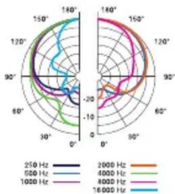
| Polar pattern | Cardioid |
| Sensitivity (1 kHz, passive) | 1.2 mV/Pa |
| Electrical impedance (1 kHz) | < 200 Ohm |
| Recommended load impedance | > 1 000 Ohm |
| Max sound pressure level (0.5% distortion) | 164 dB SPL |
| Power supply | Passive operation without phantom, or with P48 phantom power for active filters |
| Active filter settings | 3 presets (green, orange, blue) selectable with automatic 10 dB reduction |
| Connector | XLR 3-pin (pin 1 ground, 2 hot, 3 cold) |
| Dimensions (L x W x H) | 125 x 101 x 66 mm |
| Weight | 500 g |
| Housing material | Metal, front grille matte nickel, rear grille matte black |
| Cleaning | Slightly damp cloth, never wet |
| Safety | Check the compliance of the connected device (grounded outlet) |
| Environment | Separately recycle housing, electronics, cables at end of life |
| Included accessories | Transport bag, frequency chart, instruction manual |
| Operating temperature | -10 °C to +70 °C |
| Allowable relative humidity | 90% at 20 °C |
Frequently Asked Questions - D12 VR AKG
User questions about D12 VR AKG
0 question about this device. Answer the ones you know or ask your own.
Ask a new question about this device
Download the instructions for your Microphone in PDF format for free! Find your manual D12 VR - AKG and take your electronic device back in hand. On this page are published all the documents necessary for the use of your device. D12 VR by AKG.
USER MANUAL D12 VR AKG
Please read the manual before using the equipment!
MODE D'EMPLOI 18
natural_image
Close-up of a black D12 VR microphone with metallic grille and logo (no visible text beyond brand name)Inhaltsverzeichnis
natural_image
Close-up of a black D12 VR microphone with three colored indicator lights (green, red, blue) on its cap (no text or symbols on the device body)3 Anwendung
Bass Drum
radar
| Frequency | 250 Hz | 500 Hz | 800 Hz | 1000 Hz | 1200 Hz | 1400 Hz | |---|---|---|---|---|---|---| | 2500 Hz | -15 | -18 | -22 | -25 | -30 | -35 | | 5000 Hz | -12 | -16 | -20 | -23 | -28 | -33 | | 8000 Hz | -8 | -12 | -16 | -21 | -26 | -31 | | 16000 Hz | -5 | -9 | -13 | -19 | -24 | -29 | | 2000 Hz | -3 | -7 | -11 | -17 | -22 | -26 | | 4000 Hz | -1 | -5 | -9 | -15 | -20 | -24 | | 6000 Hz | 1 | -3 | -7 | -13 | -18 | -22 | | 8000 Hz | 3 | -1 | -5 | -11 | -16 | -20 | | 1000 Hz | 5 | 1 | -3 | -9 | -14 | -18 | | 1200 Hz | 7 | 3 | 1 | -7 | -12 | -16 | | 1400 Hz | 9 | 5 | 3 | -5 | -10 | -14 | | 1600 Hz | 11 | 7 | 5 | -3 | -8 | -12 | | 1800 Hz | 13 | 9 | 7 | -1 | -6 | -10 | The chart displays a radar chart with angular positions (θ) on the x-axis and frequency values on the y-axis. The frequency values are labeled at each data point along the chart. The legend indicates frequency ranges: 250 Hz, 500 Hz, 800 Hz, 1600 Hz, and corresponding frequencies for each frequency. The chart is saved as a PNG image and displayed.Table of Contents
1 Safety and Environment 11
Environment 11
2 Description....12
Introduction 12
Contents....12
Optional Accessories....12
Description....12
Connections / Controls / Display 13
Microphone operation ....14
3 Application....15
Bass Drum 15
4 Cleaning....15
Microphone 15
5 Specifications....16
1 Safety and Environment

ATTENTION
Risk of damage
Please make sure that the piece of equipment your microphone will be connected to fulfills the safety regulations in force in your country and is fitted with a ground lead.
Environment

- When the product reaches the end of its life, separate the housing, electronics and cables and dispose of all components in accordance with local waste disposal regulations.
- The packaging can be recycled. Dispose of the packaging in a suitable collection system.
2 Description
Introduction
Thank you for purchasing an AKG product. This Manual contains important instructions for setting up and operating your equipment. Please take a few minutes to read the instructions below carefully before operating the equipment. Please keep the Manual for future reference. Have fun and impress your audience!
Contents
• D12 VR microphone
- Microphone carry-case
• Frequency response chart
- User manual
Optional Accessories
For optional accessories, refer to the current AKG catalog or folder, or visit www.akg.com. Your dealer will be glad to help.
Description
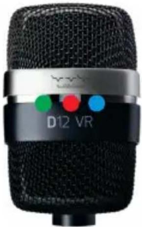
The D12 VR is a large-diaphragm cardioid dynamic microphone. Designed specifically for kick-drum recording applications, the microphone has a thin diaphragm to enhance the low frequency performance.
Without phantom power, the microphone delivers the pure character of the sound source. With phantom power enabled, one of three switchable active-filter presets can be used to quickly adapt the microphone response to suit the desired kick-drum. The filter setting can be controlled using a switch on the microphone body. In this mode the output level is also reduced by 10 dB automatically.
Active filter operation:
The implementation of an active electronic filter in a dynamic microphone is an AKG patented solution. “Phantom Power” must be supplied from the connected mixing desk in order to power the active filter circuitry. The operating principle of the active filters is based on analogue circuitry combined with a transformer. Frequency processing is performed in the filter circuit and then combined with the audio signal in the transformer. Impedance differences between the microphone and other equipment are cancelled out enabling a perfect sound regardless of the connected device. The resulting sound is especially impressive at high signal levels at which the transformer enhances the audio signal.
Connections / Controls / Display
• Standard 3-pin male XLR connector
- 3-way sliding switch for active filter selection
• 3 LEDs to indicate the switch position
Microphone operation
a Without phantom power the D12 VR operates as a normal dynamic microphone. The three active filters are bypassed and do not affect the audio signal.
b When connected to a standard phantom power supply (P48V) the output level is automatically reduced by 10 dB and one of three active filter presets can be selected using the three-way switch.
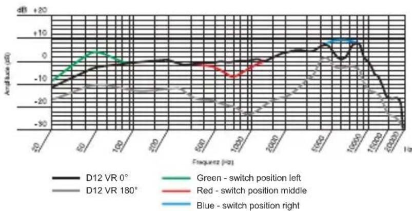
1) Switch in left position (green LED)
The midrange filter is applied as in Position 2 and a low-end boost enhances the power of the kick drum.
Recommended for use with open kick drums.
2) Switch in centre position (red LED)
A mid-range attenuation filter is active, providing more space for other instruments in the mix.
natural_image
Close-up of a black D12 VR microphone with visible color dots (green, red, blue) on its cap and body.Recommended for achieving a vintage sound.
3) Switch in right position (blue LED)
The mid-range and low-end filters are applied as in positions 1 and 2 as well as a high-end boost to enhance the presence of the kick.
Recommended for use with closed kick drums.
The switch position is clearly represented by the colour coded LEDs and hence the filter selection can be determined with ease.
3 Application
Bass Drum
Most engineers agree that it is beneficial to remove the front head when miking up the bass drum. A full drum sound is obtained by placing the microphone just outside the drum. The further inside, the drier and less boomy the sound and the better the acoustic separation of the bass drum from the rest of the kit. Pointing the microphone right toward the beater produces a harder sound culminating in a "click" when the microphone is as close as 1 or 1.5 inches to where the beater strikes the head. Directing the microphone away from this point, toward the rim of the head, will mellow the sound.
4 Cleaning
Microphone
- Use a soft cloth moistened with water to clean the surface of the microphone body.
5 Specifications
Transducer Principle: dynamic pressure gradient transducer
| Polar Pattern: cardioid | |
| Frequency Range: | 17 - 17.000 Hz (±2 dB) |
| Sensitivity at 1000 Hz passive: 1,2 mV/Pa ± -58 dBV | |
| Electrical Impedance at 1000 Hz: < 200 Ohm | |
| Recommended Load Impedance: >1.000 Ohm | |
| Maximum SPL for 0,5 % THD: 164 dB SPL | |
| Climatic Conditions: | temperature range: -10 °C - +70 °C relative humidity at +20 °C: 90 % |
| Connector Type: three-pin male standard XLR | |
| Connector Wiring: pin 1: ground pin | pin 2: AF (in phase) pin 3: AF (out phase) |
| Housing Material: metal | |
| Finish: front grille: glossy galvanized nickel matte, rear grille: matte black paint | |
| Dimensions (H x W x D): | 125 mm x 101 mm x 66 mm |
| Weight: | 500 g |
This product conforms to the standards listed in the Declaration of Conformity. To order a free copy of the Declaration of Conformity, visit http://www.akg.com or contact sales@akg.com.
Frequency Response Curve
Polar Pattern
radar
| Frequency | 250 Hz | 500 Hz | 1000 Hz | 2000 Hz | 4000 Hz | 6000 Hz | 16000 Hz | |---|---|---|---|---|---|---|---| | 250 Hz | -1.5 | -1.2 | -0.8 | -0.5 | -0.3 | -0.1 | 0.2 | | 500 Hz | -1.2 | -1.0 | -0.6 | -0.3 | -0.1 | 0.1 | 0.4 | | 1000 Hz | -0.8 | -0.6 | -0.3 | 0.1 | 0.3 | 0.5 | 0.7 | | 2000 Hz | -0.5 | -0.3 | 0.1 | 0.4 | 0.6 | 0.8 | 1.0 | | 4000 Hz | -0.2 | 0.1 | 0.3 | 0.6 | 0.8 | 1.0 | 1.2 | | 6000 Hz | 0.1 | 0.3 | 0.5 | 0.8 | 1.0 | 1.2 | 1.4 | | 16000 Hz | 0.3 | 0.5 | 0.7 | 1.0 | 1.2 | 1.4 | 1.6 |Sommaire
natural_image
Close-up of a black D12 VR microphone with visible color bands (green, red, blue) on its cap (no text or symbols beyond brand logo)2) Centre : (rouge)
line
| Frequency (%) | D12 VR 0° | D12 VR 180° | Green - switch position left | Red - position middleswitch | Blue - positions switch right | | ------------- | --------- | ----------- | ---------------------------- | --------------------------- | ----------------------------- | | 0 | -15 | -20 | -10 | -15 | -20 | | 50 | -5 | -25 | 0 | -10 | -25 | | 100 | 0 | -30 | 5 | -5 | -30 | | 150 | 5 | -35 | 10 | 0 | -35 | | 200 | 10 | -40 | 15 | 5 | -40 | | 250 | 15 | -45 | 20 | 10 | -45 | | 300 | 20 | -50 | 25 | 15 | -50 | | 350 | 25 | -55 | 30 | 20 | -55 | | 400 | 30 | -60 | 35 | 25 | -60 | | 450 | 35 | -65 | 40 | 30 | -65 | | 500 | 40 | -70 | 45 | 35 | -70 | | 550 | 45 | -75 | 50 | 40 | -75 | | 600 | 50 | -80 | 55 | 45 | -80 | | 650 | 55 | -85 | 60 | 50 | -85 | | 700 | 60 | -90 | 65 | 55 | -90 | | 750 | 65 | -95 | 70 | 60 | -95 | | 800 | 70 | -100 | 75 | 65 | -100 | | 850 | 75 | -105 | 80 | 70 | -105 | | 900 | 80 | -110 | 85 | 75 | -110 | | 950 | 85 | -115 | 90 | 80 | -115 | | 1000 | 90 | -120 | 95 | 85 | -120 | | 1050 | 95 | -125 | 100 | 90 | -125 | | 1100 | 100 | -130 | 105 | 95 | -130 | | 1150 | 105 | -135 | 110 | 100 | -135 | | 1200 | 110 | -140 | 115 | 105 | -140 | | 1250 | 115 | -145 | 120 | 110 | -145 | | 1300 | 120 | -150 | 125 | 115 | -150 | | 1350 | 125 | -155 | 130 | 120 | -155 | | 1400 | 130 | -160 | 135 | 125 | -160 | | 1450 | 135 | -165 | 140 | 130 | -165 | | 1500 | 140 | -170 | 145 | 135 | -170 | | 1550 | 145 | -175 | 150 | 140 | -175 | | 1600 | 150 | -180 | 155 | 145 | -180 | | 1650 | 155 | -185 | 160 | 150 | -185 | | 1700 | 160 | -190 | 165 | 155 | -190 | | 1750 | 165 | -195 | 170 | 160 | -195 | | 1800 | 170 | -200 | 175 | 165 | -200 | | 1850 | 175 | -205 | 180 | 170 | -205 | | 1900 | 180 | -210 | 185 | 175 | -210 | | 1950 | 185 | -215 | 190 | 180 | -215 | | 2000 | 190 | -220 | 195 | 185 | -220 | | Note: The frequency values are labeled as 'Hz' on the x-axis. The y-axis is labeled as 'dB'. There are no labels for the data series in this case. The color of the line represents the position of each position. The label 'Blue' indicates which position is right. The label 'Green' indicates which position is left. The label 'Red' indicates which position is middle. The label 'Blue' indicates which position is right. The label 'Blue' indicates which position is right. The label 'Green' indicates which position is left. The label 'Red' indicates which position is middle. The label 'Blue' indicates which position is right. The label 'Blue' indicates which position is left. The label 'Green' indicates which position is right. The label 'Red' indicates which position is middle. The label 'Blue' indicates which position is right. The label 'Blue' indicates which position is left. The label 'Green' indicates which position is left. The label 'Red' indicates which position is middle. The label 'Blue' indicates which position is right. The label 'Blue' indicates which position is left. The label 'Green' indicates which position is right. The label 'Red' indicates which position is middle. The label 'Blue' indicates which position is right. The label 'Blue' indicates which position is left. The label 'Green' indicates which position is left.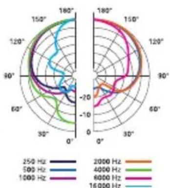
radar
| Frequency | 250 Hz | 500 Hz | 1000 Hz | 2000 Hz | 4000 Hz | 6000 Hz | 16000 Hz | |---|---|---|---|---|---|---|---| | 250 Hz | -15 | -18 | -22 | -25 | -30 | -35 | -40 | | 500 Hz | -18 | -22 | -28 | -32 | -38 | -45 | -52 | | 1000 Hz | -22 | -28 | -35 | -40 | -48 | -55 | -62 | | 2000 Hz | -25 | -32 | -42 | -48 | -55 | -65 | -75 | | 4000 Hz | -30 | -38 | -50 | -58 | -65 | -75 | -85 | | 6000 Hz | -35 | -45 | -58 | -68 | -78 | -88 | -98 | | 16000 Hz | -40 | -52 | -65 | -78 | -88 | -98 | -108 |Indice
natural_image
Close-up of a black D12 VR microphone with visible color dots (green, red, blue) on its cap and grille (no text or symbols beyond branding)natural_image
Close-up of a black D12 VR microphone with three colored indicator lights (green, red, blue) on its cap (no text or symbols on the device body)3 Aplicación
Bombo
natural_image
Close-up of a black D12 VR microphone with green, red, and blue indicator lights (no text or symbols on the device body)3 Utilização
Bombo
For other products and distributors worldwide visit www.akg.com



ROHS OK
Technische Änderungen vorbehalten. Specifications subject to change without notice. Ces caractéristiques sont susceptibles de modifications. Ci riserviamo il diritto di effettuare modifiche tecniche. Nos reservamos el derecho de introducir modificaciones técnicas. Especificações sujeitas a mudanças sem aviso prévio.
Printed in Austria on recycled paper 11/12/9100 U 13710

- Inhaltsverzeichnis
- Anwendung
- Bass Drum
- Table of Contents
- Safety and Environment
- Risk of damage
- Environment
- Description
- Introduction
- Contents
- Optional Accessories
- Description
- Active filter operation:
- Microphone operation
- Application
- Cleaning
- Microphone
- Specifications
- Sommaire
- Indice
- Aplicación
- Bombo
- Utilização
- ROHS OK
Brand : AKG
Model : D12 VR
Category : Microphone