
Skyrider 65 - Receiver TECHNISAT - Free user manual and instructions
Find the device manual for free Skyrider 65 TECHNISAT in PDF.
| Product Type | Mobile satellite antenna system for motorhome/caravan |
| Brand | TechniSat |
| Model | Skyrider 65 |
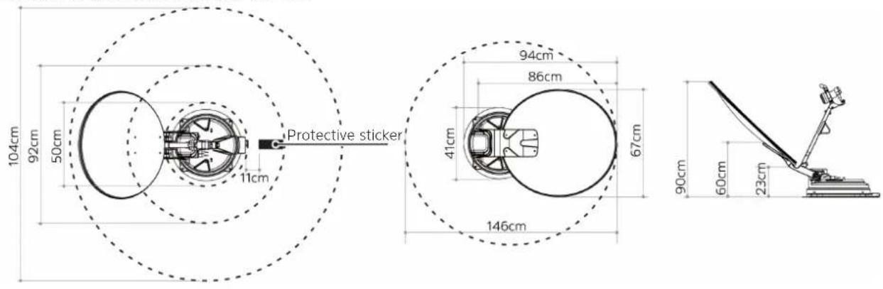
| Dimensions (folded) | 67 x 17.5 x 94 cm |
| Dimensions (unfolded) | 67 x 96.5 x 68 cm |
| Net weight (satellite installation) | 15 kg |
| Total weight (with controller and cables) | 16.5 kg |
| Power supply | 12 V DC |
| Power consumption | 50 W (during search) |
| Input frequency | 10.7 ~ 12.75 GHz |
| Polarization | Horizontal / Vertical |
| Satellite switching system | DiSEqC 1.0 / 1.1 |
| Number of LNB outputs | 1 (single version) or 2 (twin version) |
| Operating temperature | -20 °C to +60 °C |
| Package contents | Satellite antenna, controller, base, cable cover, remote control, power and signal cables, user manual |
| Main functions | Automatic satellite alignment, auto-fold, control via remote or controller, receiver current detection |
| Maintenance and cleaning | Wipe with a soft, dry cloth; do not use abrasive cleaners or solvents |
| Safety | Do not open the device, use only in temperate climates, installation by qualified professional, max vehicle speed 130 km/h with antenna folded |
| Installation | On flat roof, base glued and screwed, cables routed through roof, connection to receiver and 12 V battery |
Frequently Asked Questions - Skyrider 65 TECHNISAT
User questions about Skyrider 65 TECHNISAT
0 question about this device. Answer the ones you know or ask your own.
Ask a new question about this device
Download the instructions for your Receiver in PDF format for free! Find your manual Skyrider 65 - TECHNISAT and take your electronic device back in hand. On this page are published all the documents necessary for the use of your device. Skyrider 65 by TECHNISAT.
USER MANUAL Skyrider 65 TECHNISAT
natural_image
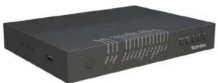
Exterior view of a black electronic device labeled 'Technetek' with ports and control buttons (no readable text beyond branding)SKYRIDER 65
natural_image
White TechniSat satellite dish mounted on a base, no visible text or symbols on the dish itself.CONTENTS
DEUTSCH 3-29
ENGLISH 31-57
FRANÇAIS 59-85
ITALIANO....87-113
NEDERLANDS....115-141
POLSKE....143-169
Bedienungsanleitung
SKYRIDER 65

natural_image
Exterior view of a black electronic device labeled 'Service' with ports and control buttons (no readable text beyond branding)
natural_image
White TechniSat satellite dish mounted on a base with antenna and support bracket (no visible text or symbols beyond brand name)TechniSat
natural_image
Simple line drawing of a desk with an arm and a separate chair, no text or symbols present- Rückseite
natural_image
Circular diagram with dots and a labeled arrow pointing left (no text or symbols on the diagram itself)natural_image
Simple circular diagram with evenly spaced dots and a small protrusion on the right side (no text or symbols)natural_image
Simple line drawing of a circular object with vertical lines inside, resembling a food or mechanical component (no text or symbols)natural_image
Simple line drawing of a circular object with a tool inserted, no text or symbols presentnatural_image
Simple line drawing of a dropper inspecting a circular object with dots (no text or symbols)natural_image
Simple line drawing of a circular object with a pointed tip and small dots, resembling a magnifying glass or lens (no text or symbols)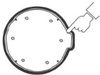
natural_image
Simple line drawing of a hand holding a circular object with holes, no text or symbols presentnatural_image
Illustration of a hand using a tool to lift a U-shaped pipe (no text or symbols)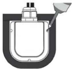
natural_image
Diagram of a U-shaped container with a funnel inserted, no text or symbols presentnatural_image
Diagram of a mechanical device with a tool inserted into a housing (no text or symbols visible)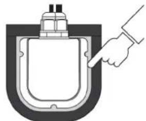
natural_image
Diagram of a hand inserting a plug into a container (no text or symbols)natural_image
Illustration of a drone flying over a tree with a car nearby, and a sad face in the sky (no text or symbols)
natural_image
Illustration of a drone flying over a tree with a car approaching, and a smiling face in the background (no text or symbols)natural_image
Exterior view of a black electronic device labeled 'Solutions' with ports and control buttons (no readable text beyond branding)
natural_image
White TechniSat satellite dish mounted on a base with antenna and support bracket (no visible text or symbols beyond brand name)TechniSat
8 Contents
8 Contents....32
9 Important information....33
9.1 Safety 33
9.2 Intended use....36
9.3 Disposal....36
9.4 Legal notices....38
9.5 Service instructions ....39
10 Figures and description 40
11 Description of the SKYRIDER 65....42
11.1 Introduction 42
11.2 Scope of delivery....42
11.3 Special features of the SKYRIDER 65....42
11.4 Installing the SKYRIDER 65....43
11.4.1 Where to install it? 43
11.4.2 Installing the satellite system 44
11.4.3 Connection diagram 50
11.5 Reception....51
12 Operation....52
12.1 Switching on & off 52
12.2 Switching the receiver power detection on / off 52
12.3 Setting up the satellite system and aligning it with a satellite....53
12.4 Home position / retracting the satellite system....53
12.5 DiSEqC setting....54
13 Troubleshooting ....55
13.1 No reaction when the controller is turned on....55
13.2 Alignment error (satellite search)....55
13.3 Other possible causes....55
32
13.4 Error messages....56
14 Technical data....57
9 Important information
Please take note of the following information to minimize safety risks, to prevent damage to the device and to make a contribution to environmental protection. Please read all the safety information carefully and keep it for future reference. Always observe all warnings and information in this quick start guide and on the rear of the device.
Caution - This identifies important information that must be observed to prevent device defects, data loss/misuse or undesired operation.
Tip - This identifies information relating to the described function, as well as to another related function that may have to be taken into account, with reference to the corresponding section in the manual.
9.1 Safety
For your own protection you should read the safety precautions carefully before using your SKYRIDER 65. The manufacturer accepts no liability for damage caused by improper handling and by not observing the following safety precautions:
The device must only be operated in an appropriate climate.
⚠️ Never open the device! Any attempt to repair the device by non-qualified persons can be dangerous and will void the warranty!
⚠️ Any required intervention must only be performed by qualified staff.
⚠️ If water has penetrated the device, switch it off and inform the Service department.
Do not expose the device to heat sources that will heat it up more than normal use.
When selecting the location for the controller to be installed make sure that it is adequately ventilated.
⚠️ If you detect a device defect, odour or smoke, considerable malfunctions, or damage to the housing, switch off the device and inform the Service department.
The device must only be connected to a mains voltage of 12V-24V DC. Never try to operate the device with another voltage.
The entire satellite system must only be installed by qualified specialist companies or similarly trained persons. Otherwise, leaks in your caravan / mobile home or even accidents caused by a releasing and / or collapsing system may occur.
Your mobile home / caravan must only be moved with the satellite system folded up. Make sure that the system is not opened up by switching it on while driving.
natural_image
Simple line drawing of a desk with an arm and a lamp, no text or symbols presentThe maximum driving speed of 130km/h must never be exceeded.

The satellite system is exposed to high loads due to wind and vibrations while driving. Therefore, the system and the components bolted to it must be regularly checked for secure location and corrected if necessary. That means, depending on the annual mileage, before departure and also during the journey when driving very long distances.
In storms and strong winds the antenna should be retracted.
A mobile home / caravan must not be driven through washing systems / car washes with a mounted satellite system.
⚠️ If the device shows any signs of damage, it must not be switched on.
When removing plugs pull on the plug, not on the cable.
⚠️ Never try to repair a faulty device yourself. Always contact one of our customer service points.
Even when switched off and on standby, the device is still connected to the mains power supply.
This device is not intended to be used by people (including children) with limited physical, sensory or mental capacities or lack of experience and/or knowledge, unless they are supervised by a person responsible for their safety or are instructed by such a person as to how to use the device.
Children must be supervised to ensure that they do not play with the device.
⚠ It is forbidden to carry out modifications to the device.
⚠️ Damaged devices or damaged accessories must not continue to be used.
⚠️ Leaking batteries can cause damage to the remote control.
⚠️ If the device is not being used for a prolonged period, remove the batteries from the remote control.
9.2 Intended use
Please read this instruction manual carefully. This is the only way to operate your device safely and correctly. Keep the instruction manual in a safe place for use at a later date.
The device is designed to receive satellite signals on stationary caravans / mobile homes.
The device has been designed for private use and not for commercial purposes.
9.3 Disposal
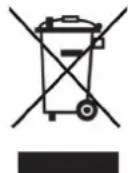
The device packaging is exclusively comprised of recyclable materials. Please sort these and take them to the "Dual System". This product is identified according to Directive 2012/19/EU on Electrical and Electronic Waste (WEEE) and, at the end of its service life, must not be disposed of with normal domestic waste, but must be taken to a collection point for recycling electrical and electronic devices.
This is indicated by the symbol on the product, the instruction manual or the packaging.
The materials are recyclable according to their labelling. An important contribution is made to protecting our environment by recycling, recovery of materials and other kinds of recycling of old devices.

Please ask local authorities for the location of the relevant disposal point. Ensure that used batteries/rechargeable batteries, as well as electronic waste, are not disposed of with household waste, but are properly disposed of (returned to the specialist dealer, hazardous waste).
Batteries/rechargeable batteries may contain poisonous substances which cause harm to health and the environment. Batteries/rechargeable batteries are subject to European Directive 2006/66/EC. They must not be disposed of with normal household waste.

Disposal instructions:
Disposal of packaging:
Your new device was protected by packaging on its way to you. All materials used are environmentally friendly and recyclable. Please collaborate and dispose of the packaging in an environmentally-friendly way. Ask for information from your dealer regarding current disposal means or your local disposal facility.

Risk of suffocation! Keep packaging and parts thereof away from children. Risk of suffocation by films and other packaging materials.
Device disposal:
Old devices constitute valuable waste. Valuable raw materials can be recovered by environmentally-friendly disposal. Consult your town or local authority as to the possibilities of environmentally-friendly and proper disposal of the device. Prior to disposal of the device, remove the batteries/rechargeable batteries contained therein.
9.4 Legal notices
TechniSat hereby declares that the SKYRIDER 65 complies with Directive 2014/53/EU. The complete text of the EU Declaration of Conformity is available at the following web address:
SKYRIDER 65 (single LNB version): http://konf.tsat.de/?ID=22699
SKYRIDER 65 (twin LNB version): http://konf.tsat.de/?ID=22700
TechniSat accepts no liability for product damage as a result of external influences, wear or improper handling, unauthorised repairs, modifications or accidents.
Changes and printing errors reserved. Version 04/20. Copying and reproduction are subject to the publisher's consent. The respective current version of the instructions can be downloaded in pdf format in the download area of the TechniSat Homepage at www.technisat.de.
i SKYRIDER 65 and TechniSat are registered trademarks of:
D-54550 Daun/Eifel, Germany
www.technisat.de
The names of the companies, institutions or brands referred to are trademarks or registered trademarks of the respective owners.
9.5 Service instructions
This product is quality-tested and provided with the legal warranty period of 24 months from the date of purchase. Please keep your receipt as proof of purchase. In the event of warranty claims please contact the product dealer.
i Note!
Should you experience a problem with this device, or for queries and information, our Technical Hotline is available:
Mon. - Fri. 8:00 am - 6:00 pm on tel.:
+49 (0) 3925 9220 1800.
If the device needs to be returned, please use the following address only:
39418 Stassfurt, Germany
CE
10 Figures and description
Satellite antenna
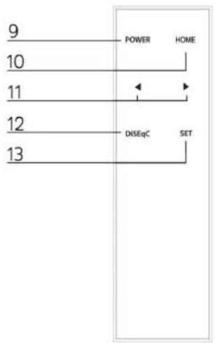
Remote control
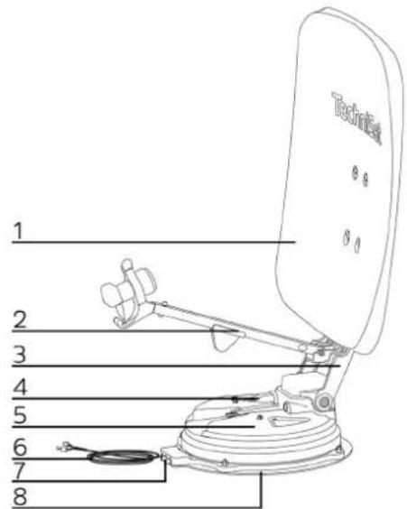
1 Satellite dish 9 Power button
2 LNB arm 10 Home button
3 Dish arm 11 Arrow keys
4 LNB connection 12 DiSEqC button
5 Alignment unit 13 SET button
6 Control cable
7 Satellite connection(s)
8 Base plate
flowchart
graph TD
    A["9"] --> B["POWER"]
    C["10"] --> B
    D["11"] --> E["←"]
    F["12"] --> G["DISEqC"]
    H["13"] --> I["SET"]
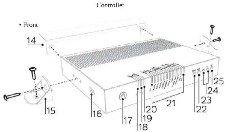
- Back
14 Cable cover
15 Holder for controller
16 USB port
17 Power button
18 Home LED
19 Lock LED
20 DiSEqC LED
21 Satellite LEDs
22 DiSEqC button
23 Home button
24 Arrow keys
25 SET button
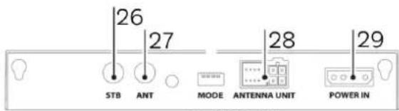
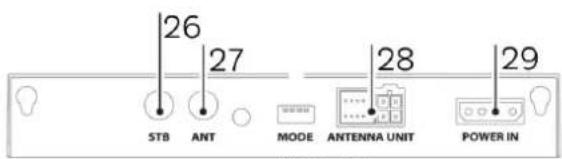
26 STB connection
27 Satellite dish connection
28 Connection controller
29 Power supply
11 Description of the SKYRIDER 65
11.1 Introduction
This manual describes the functions, installation and operation of the SKYRIDER 65 mobile satellite antenna system.
Correct and safe operation of the system can only be guaranteed by observing this manual.
Your antenna is a smart satellite TV reception system that can automatically align with the default satellites.
For general operation, ensure that the system always has a clear and unobstructed view of the desired satellite. If the satellite signal is interrupted by obstacles such as mountains, buildings, vehicles or trees, no satellite reception or only weak satellite reception is possible.
11.2 Scope of delivery
The scope of delivery includes:
Satellite antenna
1 x SKYRIDER alignment unit with base plate, 1x 65cm mirror, 1x LNB arm, 1x cable clamp, 1x protective sticker,
1 x M6x55 screw, 2 x M6x15 screw, 2 x M6x25 screw, 4 x washer, 6 x 4x16 screw, 1 x 4x10 screw
Controller
1 x controller, 1 x controller holder, 1 x cable cover, 1 x remote control, 1 x instruction manual, 4 x 4x16 screws
Cables
1 x power supply cable, 1 x signal cable (twin LNB version 2 x), 1 x STB cable, 1 x cable holder, 1 x cable screw connection,
3 x 4x16 screws
11.3 Special features of the SKYRIDER 65
The SKYRIDER 65 is a satellite reception system for camping use and has the following features:
- self-alignment
- 1 LNB connection for control and satellite signal reception
- 1 LNB connection with satellite signal for 2nd STB or 2nd connection to STB (only twin LNB version)
11.4 Installing the SKYRIDER 65
11.4.1 Where to install it?

The entire satellite system must only be installed by qualified specialist companies or similarly trained persons. Otherwise, leaks in your caravan / mobile home or even accidents caused by a releasing and / or collapsing system may occur.

The total vehicle height must not exceed 4m after installation of the satellite system when retracted and should not protrude beyond the vehicle contours.

It is not necessary to make an entry in the vehicle documents if the satellite system is at a height of more than 2m, but less than 4m and within the outer contour of the vehicle when the vehicle is laden.

The satellite system is to be installed on a solid and level roof. Whereby the entire base plate must be resting on the roof. When selecting the location for the installation, make sure that there are no obstacles in the rotation area of the satellite system, such as other installations or the like.

Direction of travel
11.4.2 Installing the satellite system
In addition to the components from the scope of delivery, to mount the satellite system requires:
1 x suitable mounting / sealing adhesive, 1 x cleaning agent, 1 x 2mm drill, 1 x 25mm drill, 1 x adhesive tape, 1 x screwdriver, 1 x 13mm wrench, flexible tape
Determine a suitable location for the installation of the satellite system as per 11.4.1.
i Be sure to pay attention to any installations that possibly exist on, in and under the vehicle roof.
Release and remove the 4 nuts connecting the alignment unit to the base plate and remove the alignment unit from the base plate.
Clean the roof surface according to the surface preparation specifications of the selected mounting adhesive.
Place the base plate in the previously determined position.
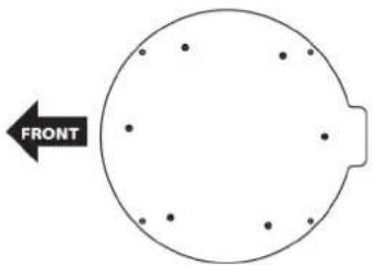
i Pay attention to the direction of travel indicated on the base plate.
natural_image
Circular diagram with dots and a labeled arrow pointing left (no text or symbols on the diagram itself)Lay a strip of the adhesive tape around the base plate at a distance of approx. 5mm.
natural_image
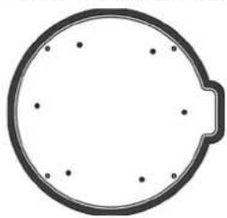
Simple circular diagram with a handle and evenly spaced dots, no text or symbols present.Put the base plate aside and apply the mounting adhesive to the roof. Keep a distance of approx. 2cm to the adhesive tape.
natural_image
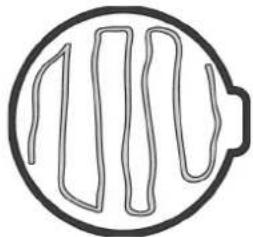
Simple line drawing of a circular object with vertical wavy lines inside, resembling a food or mechanical component (no text or symbols)Place the base plate onto the applied mounting adhesive and press down firmly.
Drill the 6 holes with the 2mm drill bit through the base plate for screwing to the vehicle roof.
natural_image
Simple line drawing of a circular object with a pointed tip and a tool inserted, no text or symbols present.Fill the holes with some of the mounting adhesive, screw the base plate down with the 4x16 screws and then apply some mounting adhesive to the screws to seal the holes.
natural_image
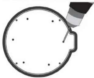
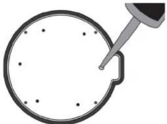
Simple line drawing of a dropper inspecting a circular object with dots (no text or symbols)i Make sure that the mounting adhesive does not protrude beyond the surface of the base plate.
Apply a thin seam of mounting adhesive around the edge of the base plate, smooth it out and remove the adhesive tape.
natural_image
Simple line drawing of a circular object with a pointed tip and small dots, resembling a mechanical or optical component (no text or symbols)
natural_image
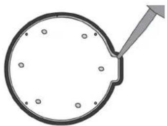
Simple line drawing of a hand holding a circular object with evenly spaced dots (no text or symbols)Place the alignment unit back on the base plate and screw together using the 4 nuts.
Find a suitable position for the cable support / cable duct through the vehicle roof.
i Be sure to pay attention to any installations that possibly exist on, in and under the vehicle roof.
Also note that the closed, rounded side of the cable holder must be facing in the direction of travel.
Mark the position by applying a strip of tape around the cable holder.
Drill a hole in the vehicle roof within this marked area with the 25mm drill bit to be able to pull the cables of the satellite system into the vehicle interior.
Connect the signal cable or, with the twin LNB version, both signal cables to the signal connection / connections of the satellite system (see connection diagram point 11.4.3) and push the rubber grommet(s) up to the stop.
Remove the nut, the screw cap and the rubber seal from the cable screw connection.
Slide the nut from below into the holder on the inside of the cable holder and screw in the cable screw connection.
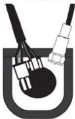
Slide the screw cap over the signal cable(s) and the control cable and insert the cables from the side into the rubber seal.
First push the control cable and then the signal cable(s) through the cable screw connection and the drilled hole.
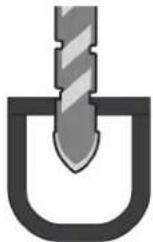
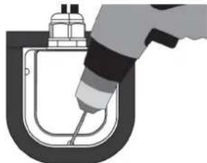
Set the cable holder onto the previously marked position and drill the 3 holes with the 2mm drill bit through the cable holder for screwing to the vehicle roof.
natural_image
Illustration of a hand using a tool to lift a U-shaped pipe (no text or symbols)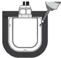
natural_image
Pure diagram of a U-shaped container with a funnel inserted, no text or symbols presentScrew the cable holder to the roof with the 4x16 screws.
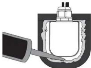
Remove the tape, apply a thin seam of mounting adhesive around the edge of the cable holder and over the screws and smooth it off.
natural_image
Diagram of a hand holding a device inside a container with a lid (no text or symbols visible)
natural_image
Diagram of a hand inserting a component into a U-shaped container (no text or symbols)Push the rubber seal into the cable screw connection and unscrew the screw cap.
Connect the satellite cable to the satellite system jack and the control cable to the controller port (see connection diagram point 11.4.3).
Connect the STB connector to the antenna jack of a satellite receiver / TV set with built-in receiver using the STB cable (see connection diagram point 11.4.3).
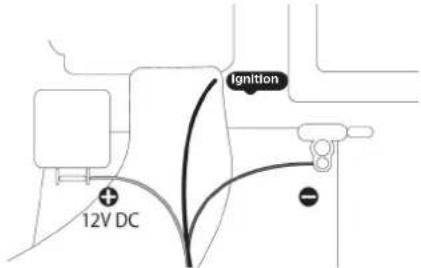
Connect the power supply cable to the on-board power supply of your vehicle following the labels on the cables and then connect it to the power supply of the controller (see point 11.4.3).
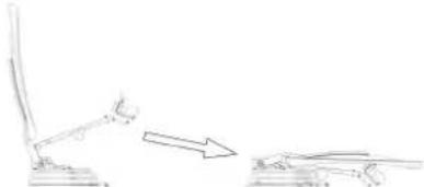
Press the Set button on the controller.
i The dish arm will now start up automatically and the system will begin to turn.
Disconnect the power supply as soon as the dish arm is upright.
Attach the dish to the dish arm and screw it in the upper holes using the M6x15 screws and in the lower holes with the M6x25 screws. Also use a washer for each screw.
Attach the LNB arm to the bottom of the dish arm and screw it on using the M6x55 screw.
Connect the coaxial cable(s) protruding from the LNB arm to the LNB jack(s) on the alignment unit and slide the grommet(s) all the way up.
Attach the coaxial cable using the cable clamps.
Apply the protective sticker in front of the satellite connection of the alignment unit at a distance of 11cm (see illustration under point 11.4.1).
Restore the connection to the power supply.
i The satellite system is now ready for use.
11.4.3 Connection diagram
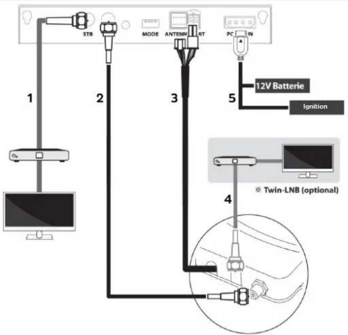
1 Cable connection from the controller to the main receiver (1st STB).
2 Signal cable connection from the satellite system to the controller.
3 Control cable connection from the satellite reception system to the controller.
4 Signal cable connection from the satellite system to the second receiver or second receiver connection (twin LNB version only).
5 Connect the power only after making all of the necessary cable connections.
11.5 Reception
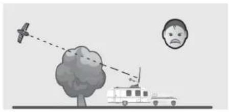
In order to receive a satellite signal, the vehicle must be parked in such a way that the satellite system has a clear view of the satellite in the direction of the equator. Make sure that there are no obstacles, such as buildings or trees in front of the antenna as these may reduce the quality of signal reception.
natural_image
Illustration of a drone flying over a tree with a vehicle nearby, and a sad face in the sky (no text or symbols)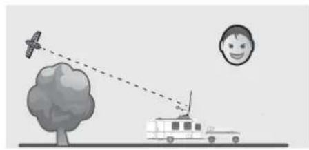
natural_image
Illustration of a drone flying over a tree with a car approaching, and a smiling face in the background (no text or symbols)i Electrical or magnetic fields near the antenna may affect reception.
i The use of non-insulated plugs will result in a loss of signal strength.
i The satellite signal may be temporarily affected due to heavy rainfall.
i Snow on the antenna can reduce the satellite signal strength; snow should therefore be removed as soon as possible.
12 Operation
12.1 Switching on & off
Press the Power button on the controller to turn it on.
If the satellite system was in the home position (point 12.4), it remains in this position after being switched on. If the satellite reception system is set up, it will automatically move to the home position after switching on the controller for safety reasons.
Press and hold the Power button on the controller or the remote control for about 2 seconds to turn off the controller.
Receiving satellite signals does not require the controller to be turned on. The controller is only needed for erecting, aligning to a satellite and retracting the dish. This means that you do not need to use the controller if you are only receiving signals from one satellite, the satellite receiving system has been aligned with the respective satellite, and the vehicle is not moving.
12.2 Switching the receiver power detection on / off
When the receiver power detection is turned on, the controller can be turned on only when the receiver connected to the STB connector is already turned on providing LNB boost voltage. This serves as a protective measure against accidental switching on of the controller and extension of the satellite system.
Move the satellite reception system to the Home position (point 12.4).
Switch off the controller by pressing and holding the Power button for 2 seconds.
Press and hold the arrow key on the left side of the controller and also press the Power button on the controller.
12.3 Setting up the satellite system and aligning it with a satellite
First use the arrow keys to select the desired satellite, unless the LED associated with the desired satellite is already lit.
By pressing the SET button, the satellite system automatically extends and aligns itself to the satellite if it was in the home position.
The lock LED flashes to signal that the SKYRIDER 65 is pointing at the desired satellite. After successful alignment, the lock LED and the LED associated with the satellite will light up.
Switching to other satellites is also possible by using DiSEqC (see point 12.5) together with your receiver, so that you do not have to resort to using the remote control of the controller or make the selection on the controller itself.
12.4 Home position / retracting the satellite system
It is essential to retract the satellite system before moving the vehicle, otherwise it could be damaged by obstacles or the wind. If this did not happen automatically when the vehicle ignition was switched on, you must start the retraction procedure manually.
With the controller turned on, press the HOME button on the controller or the remote control to retract the satellite system.
The Home LED flashes to signal that the SKYRIDER 65 is retracting. After the retraction process has ended, the Home LED lights up continuously. The controller can now be switched off and the vehicle can be moved.
If the satellite system is in the Home position and the controller was not switched off afterwards, it will switch off automatically after 15 minutes of idleness.
The satellite system must not be extended while driving.
12.5 DiSEqC setting
By default, DiSEqC is turned off. If you want to use DiSEqC, your connected receiver must support at least DiSEqC 1.0 or DiSEqC 1.1 and its satellite configuration must be set according to the tables below.
To enable or disable the DiSEqC function in the controller, press the DiSEqC button on the controller for 2 seconds.
The DiSEqC function can only be activated / deactivated in the Home position of the satellite system.
i The current status is indicated by the DiSEqC LED on the controller.
| DiSEqC 1.0 | ||
| No. Position / Option Satellite | ||
| 1 A / A | ASTRA 19.2° East | |
| 2 A / B | Eutelsat 13.0° East | |
| 3 B / A | Astra 23.5° East | |
| 4 B / B | Astra 28.5° East | |
| DISEqC 1.1 | ||
| No. LNB | Satellite | |
| 1 LNB 1 | Türksat 42.0° East | |
| 2 LNB 2 | Astra 28.5° East | |
| 3 | LNB 3 | Astra 23.5° East |
| 4 LNB 4 | ASTRA 19 | 2° East |
| 5 | LNB 5 Eutelsat 13 | 0° East |
| 6 LNB 6 | Eutelsat 9.0° East | |
| 7 | LNB 7 | Astra 4.9° East |
| 8 LNB 8 | Thor 0.8°West | |
| 9 LNB 9 | Eutelsat 5.0°West | |
| DiSEqC 1.1 | ||
| No. LNB | Satellite | |
| 10 LNB | 10 Hispasat 30.0° West | |
| 11 LNB | 1 User 1 | |
| 12 LNB | 12 User 2 | |
13 Troubleshooting
If the device does not operate as intended, check the following possible causes.
13.1 No reaction when the controller is turned on
- Check all connections again.
- The connection between the power supply and the controller.
- The connection between the controller and the antenna.
- Check if the power cord has been damaged.
- Check the polarity of the mains connection.
13.2 Alignment error (satellite search)
- Obstacles such as buildings or trees can block the satellite signals or affect the quality of signal reception. Make sure that the area to the south is clear of obstacles.
- Select another satellite, and if that works, choose your desired satellite.
- Move the system to Home position, turn the controller off and then on again and choose the desired satellite.
13.3 Other possible causes
- If the cables in the system are not connected properly, the system will not work perfectly. In the event of cable damage, please contact your local dealer.
13.4 Error messages
If the Home, Lock, and DiSEqC LEDs are lit together with any of the satellite LEDs listed below, then the controller has detected one of the errors listed below.
| Satellite LED Error | |
| Turksat Low voltage | |
| Astra 2 Tuner | |
| Astra 3 AZ motor | |
| Astra 1 EL motor | |
| Hotbird SK motor | |
| Eutelsat 9 AZ motor current | |
| Astra 4 EL motor current | |
| Thor SK motor current | |
| Eutelsat 5W EL area |
14 Technical data
| Input frequency 10.7 ~ 12.75GHz | |
| Polarization Horizontal / Vertical | |
| Min EIRP 46dBW | |
| Angular range (elevation / azimuth) 0° ~ 145° / 390° | |
| Skew Manual | |
| Satellite switching system DiSEqC 1.0/1.1 | |
| Satellite search time 180 seconds (AVG) | |
| LNB output 1 / 2 | |
| LNB output frequency 950 ~ 2,150MHz | |
| L.O. frequency 9.75 / 10.6GHz | |
| Dimensions WxHxD (retracted / ready to receive) 67cm x 17.5cm x 94cm / 67cm x 96.5cm x 68cm | |
| Weight (satellite system / total net weight) | 15 kg / 16.5kg |
| Operating temperature | -20°C - +60°C |
| Voltage supply | DC 12 V |
| Power consumption | Max. 50W (while searching) |
Mode d'emploi
SKYRIDER 65
natural_image
Exterior view of a black electronic device labeled 'Service' with ports and control buttons (no readable text beyond branding)
natural_image
White TechniSat satellite dish mounted on a base with antenna and support bracket (no visible text or symbols beyond brand name)TechniSat
1 Sommaire
1 Sommaire 60
2 Consignes importantes....61
2.1 Sécurité 61
2.2 Utilisation conforme....64
2.3 Élimination....64
4.1 Introduction....70
natural_image
Simple line drawing of a desk with a lamp and two objects on the floor (no text or symbols)natural_image
Circular diagram with dots and a labeled arrow pointing left (no text or symbols on the diagram itself)natural_image
Simple circular diagram with evenly spaced dots and a small protruding shape, no text or symbols present.natural_image
Simple line drawing of a circular object with vertical wavy lines inside, resembling a food or mechanical component (no text or symbols)natural_image
Simple line drawing of a circular object with a tool inserted, no text or symbols presentnatural_image
Simple line drawing of a dropper tiping a circular object with dots, no text or symbols presentnatural_image
Simple line drawing of a magnifying glass with a handle and circular lens (no text or symbols)
natural_image
Simple line drawing of a hand holding a circular object with holes, no text or symbols presentnatural_image
Illustration of a hand using a tool to lift a U-shaped pipe (no text or symbols)
natural_image
Pure diagram of a U-shaped container with a funnel inserted, no text or symbols presentnatural_image
Diagram of a hand holding a device inside a container with a lid (no text or symbols visible)
natural_image
Diagram of a hand inserting a component into a U-shaped container (no text or symbols)natural_image
Illustration of a weather incident with a vehicle, tree, and distant bird (no text or symbols)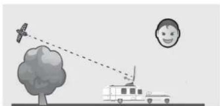
natural_image
Illustration of a drone flying over a tree with a car approaching, and a smiling face in the background (no text or symbols)natural_image
Exterior view of a black electronic device labeled 'Service' with ports and control buttons (no readable text beyond branding)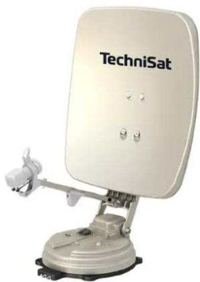
natural_image
White TechniSat satellite dish mounted on a base with antenna and support bracket (no visible text or symbols beyond brand name)TechniSat
1 Indice
1 Indice 88
2 Note importanti....89
2.1 Sicurezza 89
natural_image
Simple line drawing of a desk with a lamp and an arrow indicating motion (no text or symbols)natural_image
Circular diagram with dots and a labeled arrow pointing left (no text or symbols on the diagram itself)natural_image
Simple circular diagram with a handle and evenly spaced dots, no text or symbols present.natural_image
Simple line drawing of a circular object with vertical wavy lines inside, resembling a food or appliance outline (no text or symbols)natural_image
Simple line drawing of a circular object with a tool inserted, no text or symbols presentnatural_image
Simple line drawing of a dropper inspecting a circular object with dots (no text or symbols)natural_image
Simple line drawing of a circular object with a pointed tip and small dots, resembling a lens or dial (no text or symbols)
natural_image
Simple line drawing of a hand holding a circular object with holes, no text or symbols presentnatural_image
Illustration of a hand using a tool to lift a U-shaped pipe (no text or symbols)
natural_image
Diagram of a U-shaped container with a funnel inserted, no text or symbols presentnatural_image
Illustration of a hand inserting a plug into a container with a lid (no text or symbols)
natural_image
Diagram of a hand inserting a component into a U-shaped container (no text or symbols)natural_image
Illustration of a drone flying over a tree with a car nearby, showing communication and weather effects (no text or symbols)
natural_image
Illustration of a drone flying over a tree with a small human face and vehicle nearby (no text or symbols)natural_image
Exterior view of a black electronic device labeled 'Selective' with ports and control buttons (no readable text beyond branding)
natural_image
White TechniSat satellite dish mounted on a base, no visible text or symbols on the dish itself.TechniSat
1 Inhoudsopgave
1 Inhoudsopgave 116
natural_image
Simple line drawing of a desk with an arm and a separate table, no text or symbols presentnatural_image
Circular diagram with dots and a labeled arrow pointing left (no text or symbols on the diagram itself)natural_image
Simple circular diagram with a handle and evenly spaced dots, no text or symbols present.natural_image
Simple line drawing of a circular object with vertical lines inside, resembling a stylized food item or container (no text or symbols)natural_image
Diagram of a mechanical component with a tool inserted into a circular housing (no text or symbols)natural_image
Simple line drawing of a dropper inspecting a circular object with dots (no text or symbols)natural_image
Simple line drawing of a circular object with a pointed tip and small dots, resembling a stylized eye or lens (no text or symbols)
natural_image
Simple line drawing of a hand holding a circular object with holes, no text or symbols presentnatural_image
Illustration of a hand using a tool to lift a U-shaped pipe (no text or symbols)
natural_image
Diagram of a U-shaped container with a funnel inserted, no text or symbols presentnatural_image
Illustration of a hand inserting a plug into a container with a lid (no text or symbols)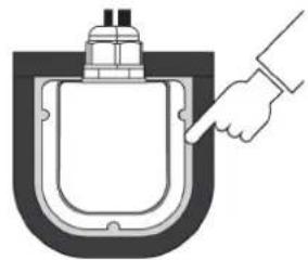
natural_image
Diagram of a hand inserting a plug into a container (no text or symbols)natural_image
Illustration of a drone flying over a tree with a car nearby, and a sad face in the sky (no text or symbols)
natural_image
Illustration of a drone flying over a tree with a car approaching, and a smiling face in the background (no text or symbols)natural_image
Exterior view of a black electronic device labeled 'Solutions' with ports and control buttons (no readable text beyond branding)
natural_image
White TechniSat satellite dish mounted on a base with antenna and support bracket (no visible text or symbols beyond brand name)TechniSat
1 Spis treści
1 Spis treści 144
natural_image
Simple line drawing of a desk with an arm and a separate chair, no text or symbols presentnatural_image
Circular diagram with dots and a labeled arrow pointing left (no text or symbols on the diagram itself)natural_image
Circular mechanical component with evenly spaced holes and a small protruding part (no text or symbols)natural_image
Simple line drawing of a circular object with vertical lines inside, resembling a stylized food or container (no text or symbols)natural_image
Simple line drawing of a circular object with a tool inserted, no text or symbols presentnatural_image
Simple line drawing of a dropper inspecting a circular object with dots (no text or symbols)natural_image
Simple line drawing of a circular object with a pointed tip and small dots, resembling a magnifying glass or dial (no text or symbols)
natural_image
Simple line drawing of a hand holding a circular object with holes, no text or symbols presentnatural_image
Illustration of a hand using a tool to lift a U-shaped pipe (no text or symbols)
natural_image
Diagram of a U-shaped container with a funnel inserted, no text or symbols presentnatural_image
Illustration of a hand inserting a plug into a container with a lid (no text or symbols)
natural_image
Diagram of a hand inserting a plug into a container (no text or symbols)natural_image
Illustration of a drone flying over a tree with a car, showing an airplane and a sad face (no text or symbols)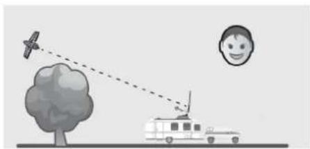
natural_image
Illustration of a drone flying over a tree with a car approaching, and a smiling face in the background (no text or symbols)
- CONTENTS
- Bedienungsanleitung
- Contents
- Important information
- Safety
- Intended use
- Disposal
- Disposal instructions:
- Legal notices
- Service instructions
- Figures and description
- Description of the SKYRIDER 65
- Introduction
- Scope of delivery
- Satellite antenna
- Controller
- Cables
- Special features of the SKYRIDER 65
- Installing the SKYRIDER 65
- Where to install it?
- Installing the satellite system
- Connection diagram
- Reception
- Operation
- Switching on & off
- Switching the receiver power detection on / off
- Setting up the satellite system and aligning it with a satellite
- Home position / retracting the satellite system
- DiSEqC setting
- Troubleshooting
- No reaction when the controller is turned on
- Alignment error (satellite search)
- Other possible causes
- Error messages
- Mode d'emploi
- Sommaire
- Indice
- Inhoudsopgave
- Spis treści
Brand : TECHNISAT
Model : Skyrider 65
Category : Receiver