
TY6011MUU - Hob Atag - Free user manual and instructions
Find the device manual for free TY6011MUU Atag in PDF.
| Product type | Teppan yaki cooking plate |
| Brand | Atag |
| Model | TY6011MUU |
| Dimensions (L x D x H) | 60 x 52 x 10 cm (estimated) |
| Net weight | Approximately 15 kg (estimated) |
| Power supply | 230 V, 50 Hz |
| Total power | 3400 W (2 x 1700 W) |
| Number of cooking zones | 2 zones (front and rear) |
| Control type | Rotary knobs with light ring |
| Temperature range | Up to 250 °C |
| Lock function | Yes, for child safety |
| Drip tray | Removable, dishwasher safe |
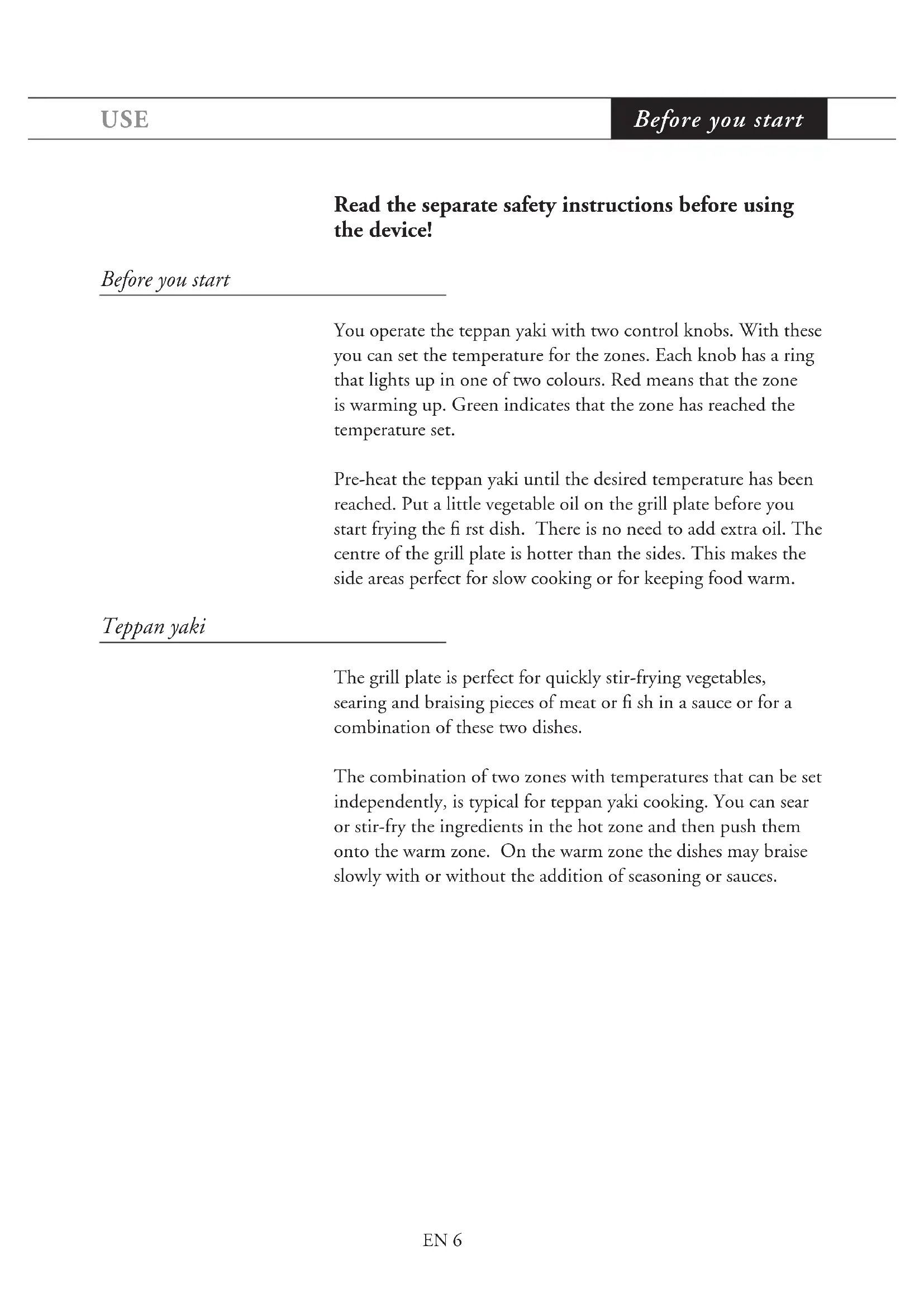
| Plate material | Stainless steel |
| Installation type | Built-in (on front or top, wood or stone) |
| Daily cleaning | Lemon juice and water on hot surface |
| Cleaning stubborn stains | Warm soapy water, non-abrasive sponge |
| Safety | Temperature control, overheat protection |
| Residual heat indicator | Via light ring (red/green) |
| Certifications | Compliant with CE standards |
| Package contents | Cooking plate, control box, drip tray, manual |
| Warranty | 2 years (to be verified) |
| After-sales service | Contact details on warranty card |
Frequently Asked Questions - TY6011MUU Atag
User questions about TY6011MUU Atag
0 question about this device. Answer the ones you know or ask your own.
Ask a new question about this device
Download the instructions for your Hob in PDF format for free! Find your manual TY6011MUU - Atag and take your electronic device back in hand. On this page are published all the documents necessary for the use of your device. TY6011MUU by Atag.
USER MANUAL TY6011MUU Atag
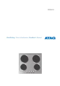
You will find the addresses and phone numbers of the service organisation on the guarantee card.
gebruiksaanwijzing
Teppan Yaki
instructions for use
Teppan Yaki
ATAG
TY3011M
TY6011M
700002149200
NL
"Front" of "top" montage
"Hout" of "steen" montage
"Front"-oder "Top"-Montage
Switching on and off 8
Dripping pan 9
Maintenance
Daily cleaning 10
Stubborn stains 11
Faults
Temperature limitation 12
Fault table 12
Installation instructions
Important matters 13
Installation situations 14
Installation instruction "Front" 15
Installation instruction Top - Wood 19
Installation instruction Top - Stone 25
Installation instruction Puzzelo 32
Drawing template 33
Appendices
Disposal of appliance and packaging 34
Technical data 34
Wholesome and nourishing food is important for a healthy lifestyle. Teppan yaki is an excellent method of preparing healthy food, the Japanese way. Ingredients are first cut into small pieces and then stir-fried in very little oil. This way, everything remains fresh, tasty and full of vitamins. And this is what modern cooking is all about. With your teppan yaki you will find that wholesome and tasty combine very well.
With the teppan yaki you will be able to quickly prepare light and tasty meals. Crisp and low in fat as is customary in Japanese cuisine. But of course this does not mean that you can only use the teppan yaki for Japanese food. Whether it is just a quick meal for yourself or a dinner party for your friends and family, the teppan yaki guarantees a fast and unrivalled culinary adventure.
This manual describes how to make optimum use of your teppan yaki. Store this manual in a safe place. The manual serves as a reference for the service department. Therefore, please paste the data card in the space provided at the back of the manual.
Enjoy your teppan yaki!
Pictograms used

important information
tip
TY3011M
TY6011M
TY3011M
- Teppan yaki 33cm 1700 watt
- Control knob LEFT (front zone 850 watt)
- Control knob RIGHT (rear zone 850 watt)
TY6011M
- Teppan yaki 60 cm 3400 watt
- Control knob LEFT (front zone 1700 watt)
- Control knob RIGHT (rear zone 1700 watt)
Read the separate safety instructions before using the device!
Before you start
You operate the teppan yaki with two control knobs. With these you can set the temperature for the zones. Each knob has a ring that lights up in one of two colours. Red means that the zone is warming up. Green indicates that the zone has reached the temperature set.
Pre-heat the teppan yaki until the desired temperature has been reached. Put a little vegetable oil on the grill plate before you start frying the first dish. There is no need to add extra oil. The centre of the grill plate is hotter than the sides. This makes the side areas perfect for slow cooking or for keeping food warm.
Teppan yaki
The grill plate is perfect for quickly stir-frying vegetables, searing and braising pieces of meat or fish in a sauce or for a combination of these two dishes.
The combination of two zones with temperatures that can be set independently, is typical for teppan yaki cooking. You can sear or stir-fry the ingredients in the hot zone and then push them onto the warm zone. On the warm zone the dishes may braise slowly with or without the addition of seasoning or sauces.
Operation
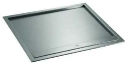
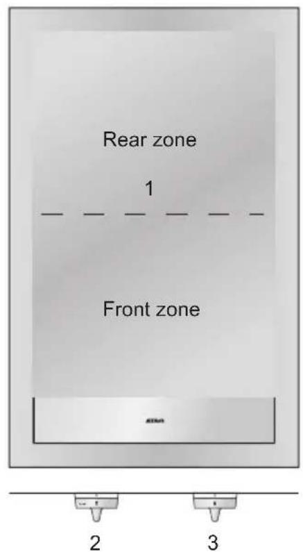
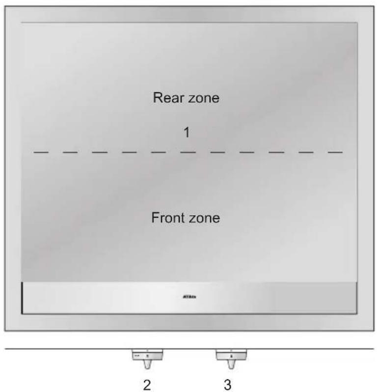
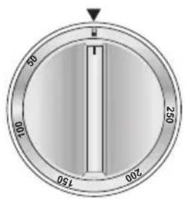
The teppan yaki contains two thermostatically controlled heating elements that can be set independently of each other. The grill plate consists of two zones: a front zone and a rear one. You set the temperatures for each zone with the two control knobs. The maximum temperature you can set is 250ircC .
Safety lock
You unlock the safety feature by pressing the button in the rosette.
Safety lock cancel (appliance switched on)
Safety lock switch on (appliance switched off)
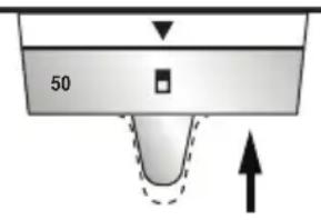
Switching on
zero position Switching on
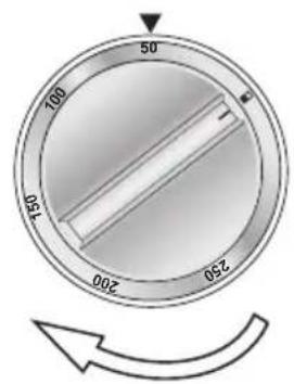
Switching off
Press the knob of the desired zone as far as it will go. Then turn it clockwise to set the right temperature. The light ring turns red to indicate that the zone is warming up. When the zone has reached the temperature set, the ring turns green: the appliance is ready for use.
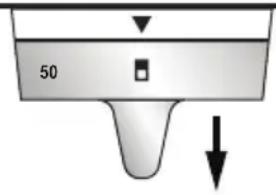
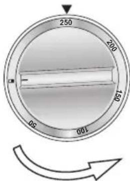
Switching off
Always turn the knob anticlockwise to return to the zero setting. You cannot reach the zero setting by turning the knob clockwise. After the knob has sprung forward again, the safety lock is activated.
Residual heat
Please remember that it takes some time for the teppan yaki to cool down after switching off.
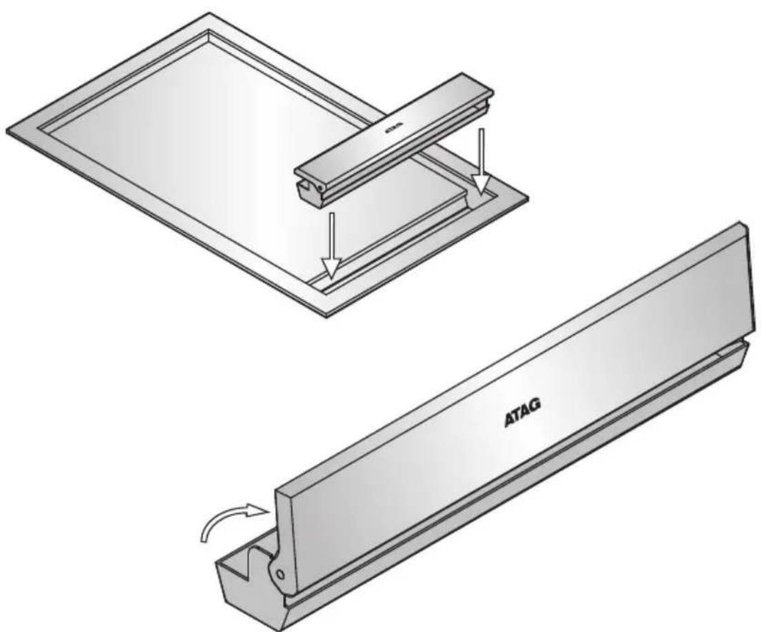
Dripping pan
The purpose of the dripping pan is the disposal of fried residue, fluid and excess oil or fat. Larger pieces of residue may be shoved into the dripping pan during cooking.
The dripping pan is removable so that you can dispose of the residue in the dustbin after you have finished cooking. The dripping pan is dishwasher-friendly.

You may use the ornamental lid to cover the dripping pan during and after cooking when the teppan yaki is cooling down.
Never scrape off your spatulas on the ornamental lid. This could scratch the lid.
Daily cleaning
It is advisable to clean the teppan yaki immediately after use. This way you avoid residue burning into the plate and thus causing stains that may be difficult to remove.
Daily cleaning is best done with lemon juice and water. Pour this liquid onto the frying area when it is still quite hot (100ircC) . The liquid soaks off the residue so that you can dispose of it in the dripping pan. Keep the teppan yaki switched on at a lower temperature for a short time. After the grill plate has cooled down use some kitchen paper to wipe away the residue and the water. You may then dry the teppan yaki with kitchen paper or a dry towel.
Stubborn stains
Stubborn marks on a stainless steel grill plate are best removed with a solution of warm water and washing-up liquid. You can use a cleaning agent for stainless steel to clean the frame. Always polish in the direction of the steel structure to avoid shine spots. Never use anything sharp like steel wool or scourers. These scourers cause scratches in the brush structure. Scouring and polishing will cause shine spots on the frying area (this kind of damage is not covered by the warranty).
If the above methods do not help to remove the stains, you can clean the grill plate with a non-scratch scouring pad, which can be ordered online at www.hps.nl. Remember to treat the entire area in order to avoid discolouring. Also, as a follow-up treat the grill plate with a polish or maintenance agent for stainless steel. Please note that over the years the surface will slightly discolour.
Never use aggressive abrasives. They leave scratches in which dirt and lime can accumulate. But if you should use an abrasive anyway, please polish in the direction of the finish.
In case of an electrical failure, please check all fuses and electrical connections in your home before you contact the service department.
Temperature limitation
When the teppan yaki has been switched on, a sensor continuously monitors the temperature of the parts of the grill plate. If the temperature gets too high, the power of the grill plate is automatically reduced.
Fault table
| Symptom Possible cause Solution | ||
| A slight smell is noticeable the first few times that you use the grill plate. | Appliance heating up. | This is normal and the smell will disappear after you have used the teppan yaki a few times. Ventilate your kitchen. |
| The grill plate becomes too hot during frying and will not remain at the set temperature. | The thermostat has broken down. | Contact the service department. |
| The knobs do not show any colour. The | the appliance has broken down. | Contact the service department. |
Important matters
- Do not use the teppan yaki if it is damaged.
- Never open the casing of the teppan yaki. This may only be done by a qualifi ed installer.
- Ensure that the fl exes of electrical appliances, c.g. a mixer, do not touch the hot grill zone.
- Always disconnect the appliance from the electronic power supply before any repair work is carried out. You do this by unplugging the appliance, by switching off the fuse(s) or, if you have a permanent connection, by setting the switch on the power supply lead to zero.
- Do not use a teppan yaki that is broken or contains cracks. Switch off the appliance immediately, unplug it from the power supply to avoid any electrical shocks and call the service department.
- The connection must comply with all national and local regulations.
The appliance must always be earthed. - The connection cable should hang unobstructed and not run the risk of being hit by a drawer.
- Ensure that the teppan yaki is built into a fl at worktop.
- The walls and the worktop surrounding the appliance should be heat-resistant to at least 85ircC .
- The warranty does not cover any damage resulting from a wrong connection, faulty assembly or improper use.
- The cables connecting the teppan yaki to the control box should not be bent, twisted or pressed down by an object. Ensure that this does not happen when unpacking and installing the teppan yaki.
- If the connecting cable is damaged, it may only be replaced by the manufacturer, the manufacturer's service organisation or equivalently qualified persons, in order to avoid dangerous situations.
- Place a protective plate under the hotplate to prevent touching of the hot underside of the hotplate.
Installation situations
Dependent on the installation situation, there are several instructions for installing the teppan yaki into a worktop. Which instructions to use depends on the position of the control knobs ("front" or "top") and the worktop material selected ("wood" or "stone"). Also special sawing measurements apply when integrating a teppan yaki with the ATAG Magna Puzzelo appliances HI3171M, HG3111M and WO3111M.
"Front" or "top"
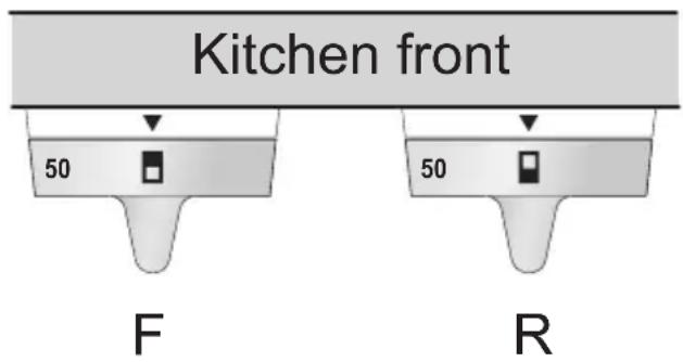
With "front" mounting, the control knobs are fitted into the kitchen front. With "top" mounting the control knobs are fitted into the worktop.
"Wood" or "stone"
"Wood" stands for all woodlike worktops that can be drilled into, e.g. wood, plywood and chipboard. "Stone" represents all stony worktops that are non-drillable, like marble or granite.
Use the table below to select the correct instruction for building in the appliance. Please select the desired installation situation and adhere to the corresponding order for building in the appliance.
| Installation situation table Worktop material | |||
| Wood Stone | |||
| Knob location Knobs inside | side the kitchen front | “Front” | |
| Knobs inside the worktop | Top-wood Top-stone | ||
| Installation next to a Magna Puzzelo appliance Puzzelo | |||
Attention: The control knobs cannot be mounted on the rear wall.
Before you start
Read the relevant installation instruction carefully to see if the conditions for building in the appliance have been met.
Installation instruction "Front"
Attention: the following instruction applies only to an installation situation whereby the control knobs are in the kitchen front, in combination with a "wooden" or "stone" worktop. See the "Installation situation table" on page 14.
Built-in dimensions
- Create the cut-out for the teppan yaki.
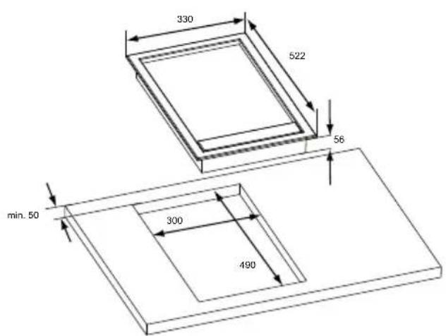
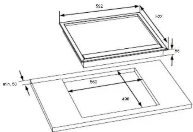
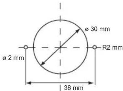
- The control box can be mounted on kitchen fronts with a maximum thickness of 40 mm . Create the cut-outs for the control knobs in the kitchen front. Use the drawing template on page 33.
| If worktop has thickness of: x becomes: | |
| < 56 mm x = 51 mm | |
| > 56 mm | x = 51 mm + (56 - worktop thickness) |
Wooden worktops
If necessary, treat the sawn ends of wooden worktops with scaling varnish, to prevent swelling of the worktop by moisture.
Order in which to build in the appliance
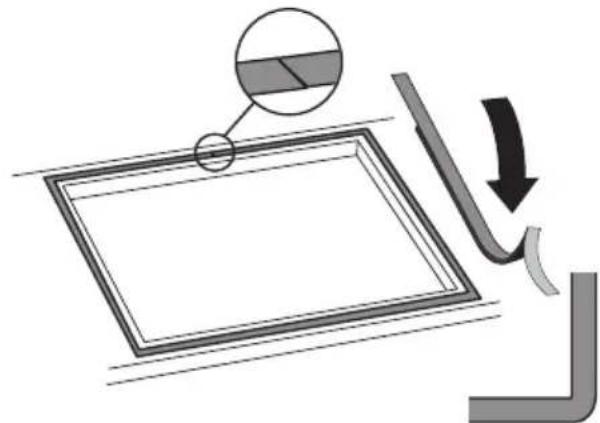
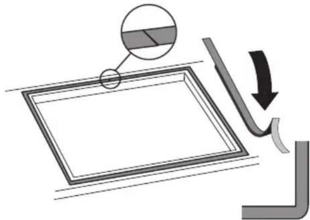
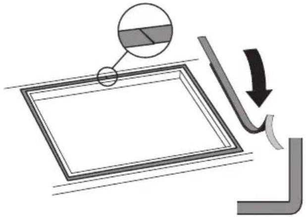
- Turn the appliance upside down and place it on the worktop. Remove the protective foil from the sealing tape and apply the tape around the cut-out in the worktop. Start at the rear side of the appliance and tape the sealing strip along the corners. Make sure that the ends of the sealing strip fit tightly together.
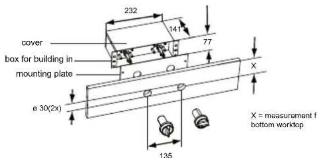
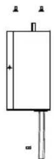
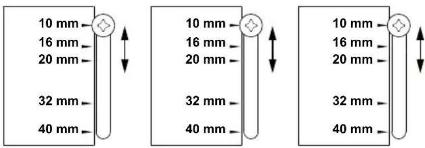
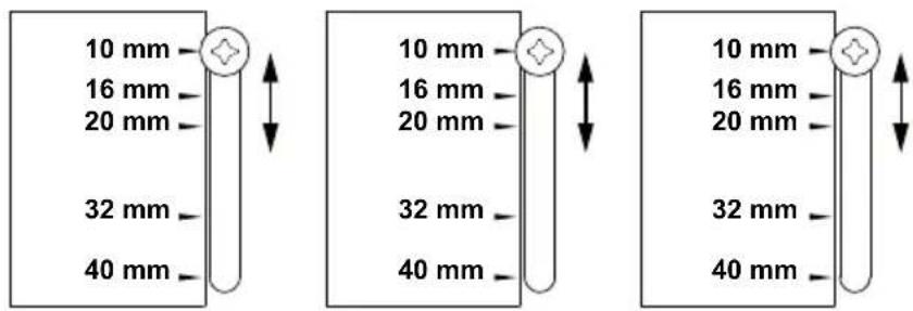
- Measure the thickness of the kitchen front. Set the control box to this thickness by correctly positioning the three screws on the bottom of the control box. The measurements on the sticker correspond with the thickness of the kitchen front.
- Position the control box so that the cover of the box faces
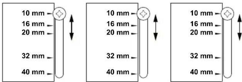
upwards.
- Remove the protection plate.
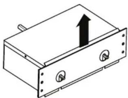
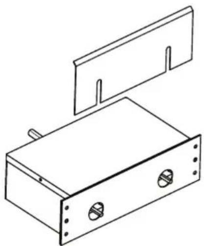
-
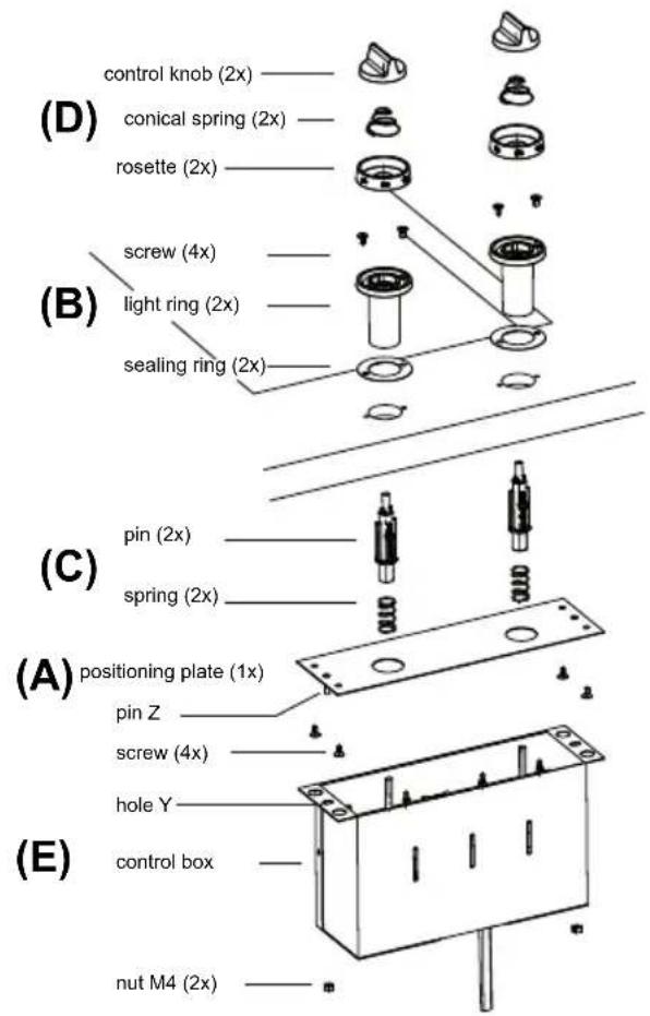
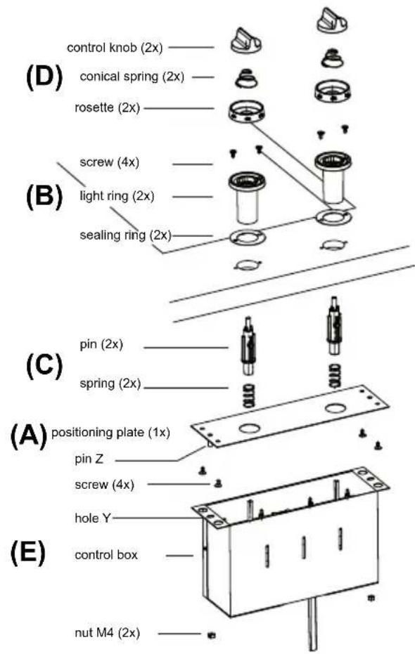
Screw the positioning plate (A) against the rear of the kitchen front with the screws supplied. The holes for the control knobs should be aligned. Use the light rings as fitting pins.
-
Now press the light rings (B) from the front through the holes in the kitchen front and screw them tight with the screws supplied.
-
Place the springs onto the pins (C) and push them from the rear through the light rings in the kitchen front.
Place the conical springs on the control knobs (D).
The teppan yaki comes with two sets of rosettes. For this
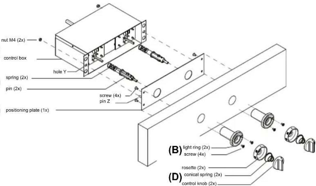
(E)
(C)
(A)
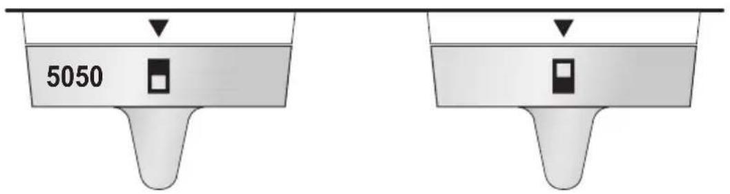
installation situation you need to use the following rosettes so that the temperatures are easy to read. Attention: the rosette with the symbol belongs to the front zone, the rosette with the symbol belongs to the rear zone).
- Press the rosettes from the front onto the pins.
- Press the control knobs onto the pins.
- Lead the control box and the mains plug through the cutout in the worktop.
- Position the control box (E) against the positioning plate so
that pin Y falls into hole Z.
- Use the nuts that were supplied with the product to secure the control box to the positioning plate.
- Turn the teppan yaki over and place it in the cut-out.
- Place the dripping pan into the teppan yaki.
- Connect the appliance to the mains. The hob is now ready for use.
- Check if the appliance works properly.
- Give the user manual to your client or, if you own the teppan yaki, store the manual in a safe place.
Installation Instruction Top-wood

Attention: the following instruction applies only to an installation situation whereby the control knobs are in the worktop, in combination with a "wooden" worktop. See the "Installation situation table" on page 14.
Before you start
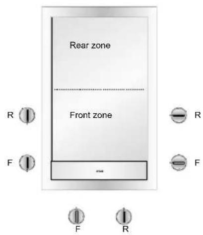
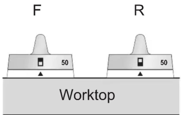
Choose the right position for the control knobs: in front, to the left or to the right of the teppan yaki. You can position the knobs in one of the following ways. This ensures that you can read the temperature indication on the knob from the user's position.
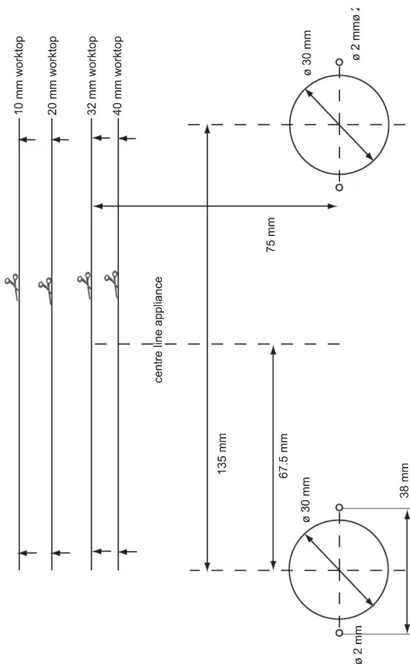
Built-in dimensions
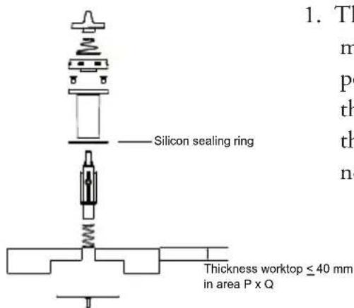
- The control box can be mounted on worktops with a maximum thickness of 40 mm . If the worktop at the position of the control knobs is thicker than 40 mm , refer to the illustration opposite to create a cut-out in the bottom of the worktop. Measure the thickness of the worktop and, if necessary, create this cut-out in the worktop.
-
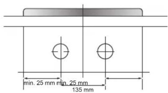
Create the cut-outs in the worktop for:
-
the teppan yaki
- the control knobs
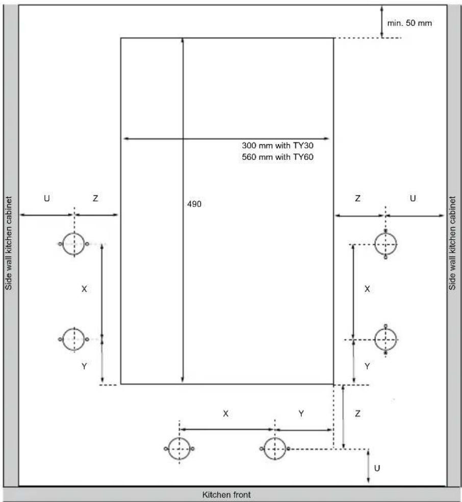
X = 1 3 5 mm
Y = . 2 5 mm; . 1 7 8 mm
Z = . 7 5 mm; . 1 2 5 mm
U = . 5 0 mm
Wooden worktops
If necessary, treat the sawn ends of wooden worktops with sealing varnish, to prevent swelling of the worktop by moisture.
Change zero position knob

If you wish you may turn the control knobs 90irc in relation to the control box so that the zero position of the knob is set in the right direction. Follow the steps as described below.
Ensure that the appliance is disconnected from the power supply before you start.
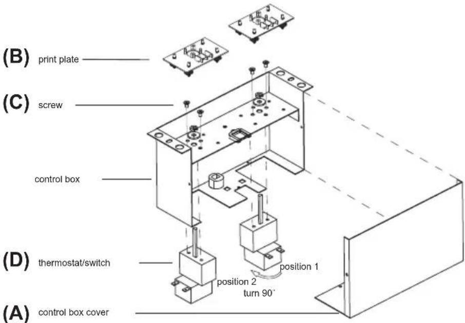
- Unscrew the cover of the control box and remove the cover (A).
- Carefully remove the print plates from their supports (B) and unscrew the thermostat/switch combinations (D) by loosening the screws (C).
- Change the position of the thermostat/switch combination. The figure shows a 90irc turn to the right from position 1 to position 2.
- Ensure that you do not bend the capillary lead of the thermostat.
Order in which to build in the appliance
- Turn the appliance upside down and place it on the worktop. Remove the protective foil from the sealing tape and apply the tape around the cut-out in the worktop. Start at the rear side of the appliance and tape the sealing strip along the corners. Make sure that the ends of the sealing strip fit tightly together.
- Measure the thickness of the worktop. Set the control box to this thickness by correctly positioning the three screws on the bottom of the control box. The sizes indicated correspond to the thickness of the worktop.
- Use the screws supplied to fasten the positioning plate (A) against the bottom of the worktop so that the holes are aligned. Use the light rings as fitting pins.
- When mounting the knobs into the worktop the sealing rings (B) should be mounted underneath the light rings.
- Place the light rings (B) from the top through the holes in the worktop and fasten them from the top with the screws supplied.
- Place the springs on the pins (C) and push them from the bottom through the light rings in the worktop.
-
Place the conical springs on the control knobs (D).
-
The teppan yaki comes with two sets of rosettes. For this installation situation you need to use the following rosettes so that the temperatures are easy to read. Attention: the rosette with the symbol belongs to the front zone, the rosette with the symbol belongs to the rear zone).

- Press the rosettes from the top onto the pins.
- Press the control knobs onto the pins.
- Lead the control box and the mains plug through the cutout in the worktop.
- Position the control box (E) against the positioning plate so that pin Y falls into hole Z.
- Use the nuts that were supplied with the product to secure the control box to the positioning plate.
- Turn the teppan yaki over and place it in the cut-out.
- Place the dripping pan into the teppan yaki.
- Connect the appliance to the mains. The hob is now ready for use.
- Check if the appliance works properly.
- Give the user manual to your client or, if you own the teppan yaki, store the manual in a safe place.
Installation Instruction Top - Stone

Attention: the following instruction applies only to an installation situation whereby the control knobs are in the worktop, in combination with a "stone" worktop. See the "Installation situation table" on page 14.
Before you start
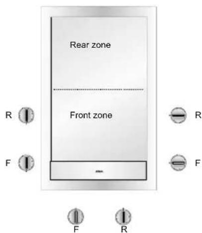
Choose the right position for the control knobs: in front, to the left or to the right of the teppan yaki. You can position the knobs in one of the following ways. This ensures that you can read the temperature indication on the knob from the user's position. Before you start, read the "Change zero position knob" paragraph.
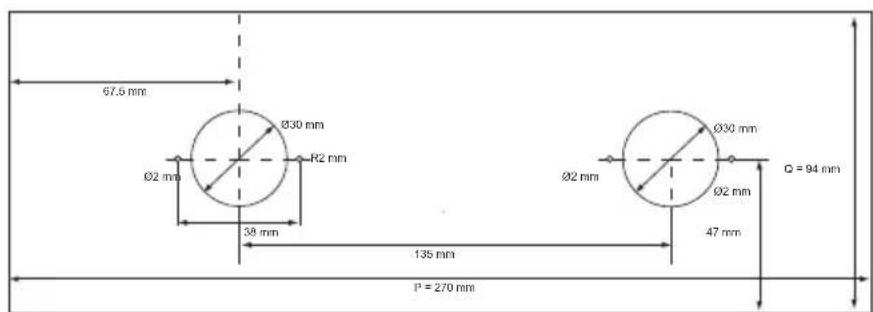
Built-in dimensions
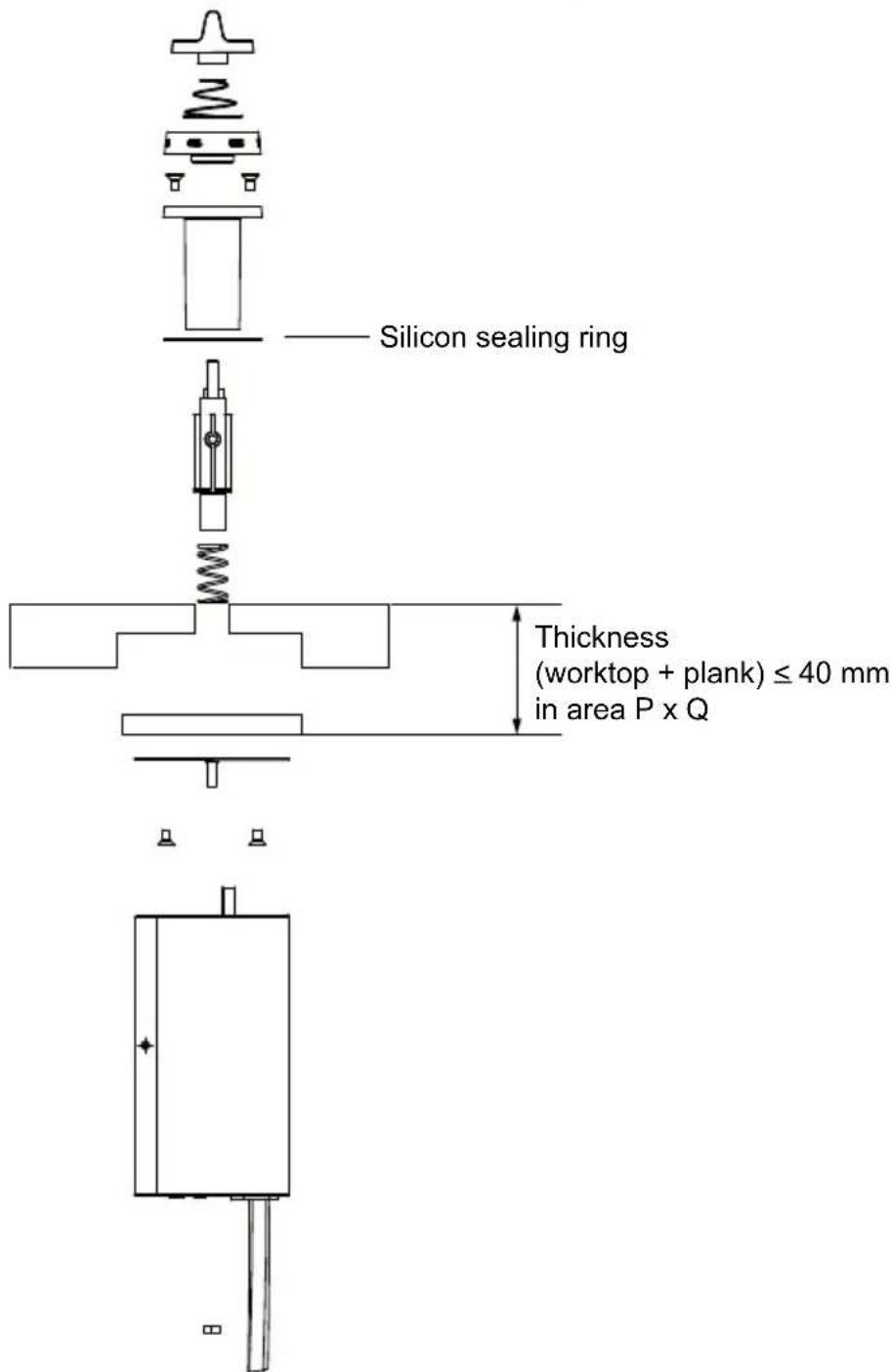
- Both the control box and the light rings are fixed with screws. You need to create a possibility to fix the control box and the light rings. You may do this by glueing a small plank to the bottom of the granite/natural stone worktop. Add the thickness of the plank to that of the worktop.
- The control box can be fixed to worktops with a maximum thickness of 40mm (including the plank used to fix the control box). If the worktop (including the plank) at the position of the control knobs is thicker than 40mm , refer the illustration above to create a cut-out in the bottom of the worktop. Measure the thickness of the worktop and, if necessary, create this cut-out in the worktop.
-
Create the cut-outs in the worktop for:
-
the teppan yaki
- the control knobs
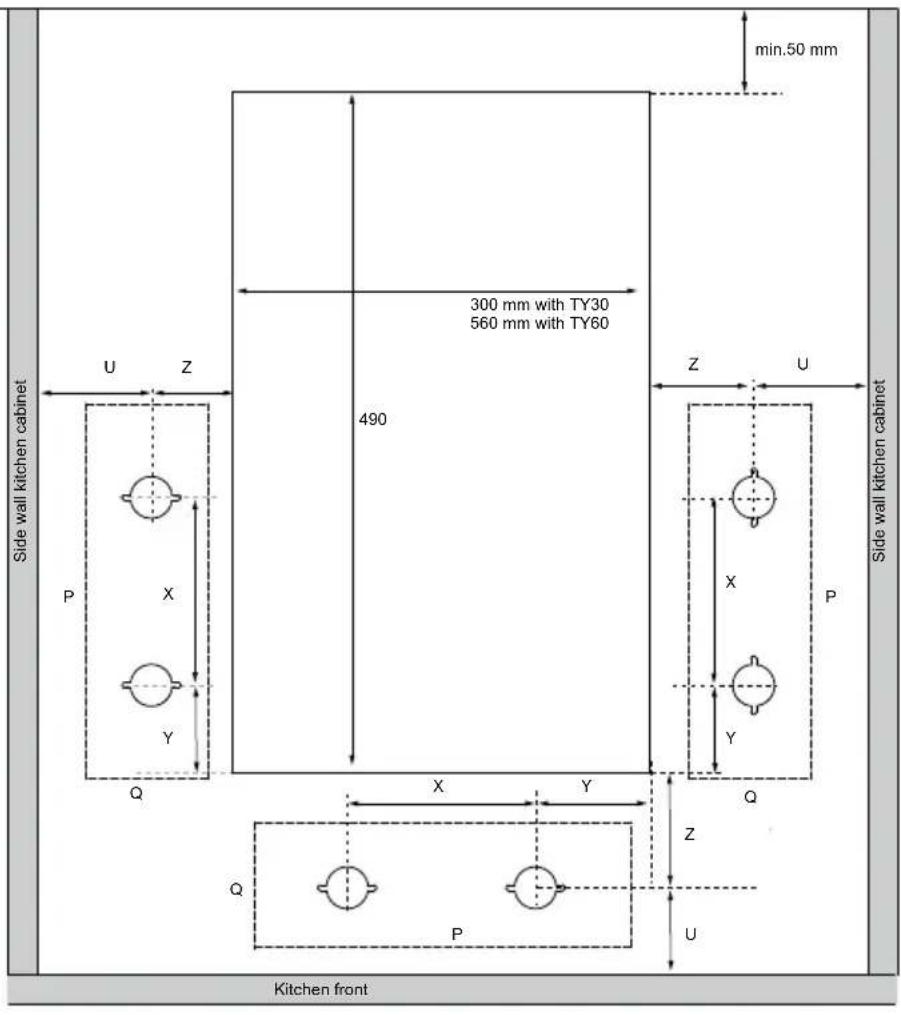
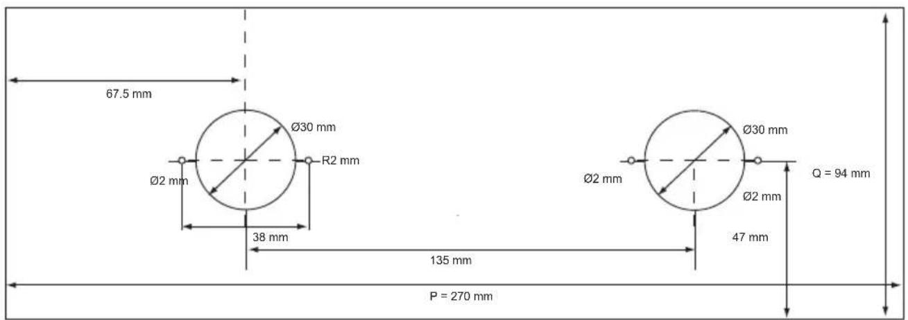
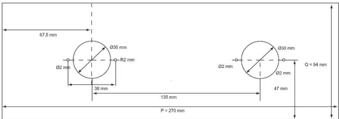
X = 1 3 5 mm Y = . 2 5 mm; . 1 7 8 mm Z = . 7 5 mm; . 1 2 5 mm U = . 5 0 mm P = 2 7 0 mm Q = 9 4 mm
Change zero position knob
If you wish you may turn the control knobs 90irc in relation to the control box so that the zero position of the knob is set in the right direction. Follow the steps as described below.
Ensure that the appliance is disconnected from the power supply before you start.

- Unscrew the cover of the control box and remove the cover (A).
- Carefully remove the print plates from their supports (B) and unscrew the thermostat/switch combinations (D) by loosening the screws (C).
- Change the position of the thermostat/switch combination. The figure shows a 90irc turn to the right from position 1 to position 2.
- Ensure that you do not bend the capillary lead of the thermostat.
Order in which to build in the appliance
- Turn the appliance upside down and place it on the worktop. Remove the protective foil from the sealing tape and apply the tape around the cut-out in the worktop. Start at the rear side of the appliance and tape the sealing strip along the corners. Make sure that the ends of the sealing strip fit tightly together.
- Measure the thickness of the worktop. Set the control box to this thickness by correctly positioning the three screws on the bottom of the control box. The sizes indicated correspond to the thickness of the worktop.
- Use the screws supplied to fasten the positioning plate (A) against the bottom of the worktop so that the holes are aligned.
- When mounting the knobs into the worktop the sealing rings (B) should be mounted underneath the light rings.
- Place the light rings (B) from the top through the holes in the worktop and fasten them from the top with the screws supplied.
- Place the springs on the pins (C) and push them from the bottom through the light rings in the worktop.
-
Place the conical springs on the control knobs (D).
-
The teppan yaki comes with two sets of rosettes. For this installation situation you need to use the following rosettes so that the temperatures are easy to read. Attention: the rosette with the symbol belongs to the front zone, the rosette with the symbol belongs to the rear zone).
- Press the rosettes from the top onto the pins.
- Press the control knobs onto the pins.
- Lead the control box and the mains plug through the cutout in the worktop.
- Position the control box (E) against the positioning plate so that pin Y falls into hole Z.
- Turn the teppan yaki over and place it in the cut-out.
- Place the dripping pan into the teppan yaki.
- Connect the appliance to the mains. The hob is now ready for use.
- Check if the appliance works properly.
- Give the user manual to your client or, if you own the teppan yaki, store the manual in a safe place.
Installation instruction Puzzle
If you wish to install a teppan yaki a short distance from an ATAG Magna Puzzelo appliance (HI3171M, HG3111M, WO3111M or FR3111M), refer to the relevant teppan yaki installation instruction. You will find the right instruction in the table on page 14.
If you wish to install a teppan yaki right next to an ATAG Magna Puzzelo appliance, refer to the chapter in the ATAG Magna Puzzelo appliance describing how to link the two appliances.
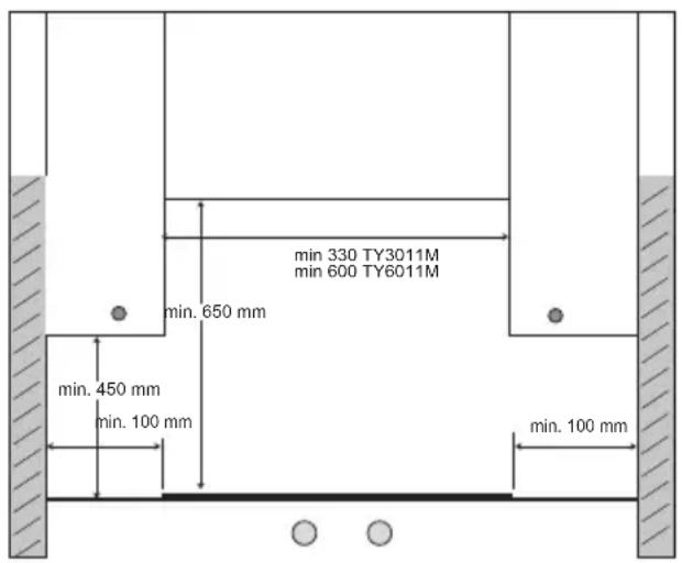
Free space required around the appliance
To ensure a safe use, there must be sufficient space around the teppan yaki. Check to see whether that space is available.
Disposal of appliance and packaging
The packaging of this appliance is recyclable. It could have been made from:
cardboard;
polythene foil (PE);
- CFK-free polystyrene (PS-hard foam).
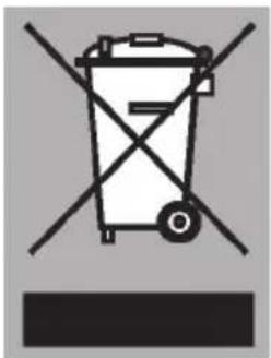
You need to dispose of these materials responsibly in accordance with offcial regulations. To draw attention to the fact that the segregated processing of electric household appliances is compulsory, this appliance carries the symbol of a crossed-out dustbin.
This means that at the end of its working life, you may not dispose of the appliance as household refuse. Instead, you should hand it in at a special refuse collection centre run by the local authority or at a dealer's providing this service.
Segregated processing of household appliances such as this grill plate, avoids any negative effects on the environment and public health that might otherwise occur. It enables the recovery of the materials used in the production of this appliance, thus realising considerable savings in terms of raw materials and energy.
Technical data
TY3011M: 230V - 50Hz - 1700W
TY6011M: 230V - 50Hz - 3400W

- NL
- "Front" of "top" montage
- "Hout" of "steen" montage
- "Front"-oder "Top"-Montage
- Maintenance
- Faults
- Installation instructions
- Appendices
- TY3011M
- TY6011M
- Read the separate safety instructions before using the device!
- Operation
- Safety lock
- Switching on
- Switching off
- Residual heat
- Dripping pan
- Daily cleaning
- Stubborn stains
- Temperature limitation
- Fault table
- Important matters
- Installation situations
- "Front" or "top"
- "Wood" or "stone"
- Before you start
- Installation instruction "Front"
- Built-in dimensions
- Wooden worktops
- Order in which to build in the appliance
- Installation Instruction Top-wood
- Change zero position knob
- Installation Instruction Top - Stone
- Installation instruction Puzzle
- Free space required around the appliance
- Disposal of appliance and packaging
- Technical data
Brand : Atag
Model : TY6011MUU
Category : Hob