Primo Viaggio 435 Nido - Car seat PEG PEREGO - Free user manual and instructions
Find the device manual for free Primo Viaggio 435 Nido PEG PEREGO in PDF.
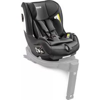
| Product type | Child car seat (carrycot) compatible with Peg Perego stroller |
| Brand | Peg Perego |
| Model | Primo Viaggio 4•35 Nido |
| Maximum child weight | 22.7 kg (50 lbs) |
| Maximum child height | 110 cm (43 inches) |
| Attachment system | T-Matic (quick attachment on Peg Perego chassis) |
| Safety harness | 5-point, height adjustable to 3 positions |
| Canopy | Yes, with visibility window (zipper) |
| Front bar | Removable (unclips via side buttons) |
| Basket (under chassis) | Maximum capacity 7 kg |
| Handle pouch | Maximum capacity 0.2 kg |
| Bottle holder | Maximum capacity 0.5 kg (do not put hot drink) |
| Front wheels | Swivel or fixed (lock with lever) |
| Parking brake | Yes, on the chassis |
| Safety standards | ASTM F833 (compliant with requirements) |
| Recommended age | From birth up to about 4 years (up to 22.7 kg) |
| Materials | Plastic, metal, fabric |
| Chassis cleaning | Damp cloth, no solvents |
| Fabric parts cleaning | Brush to remove dust, wash according to label (no bleach, no ironing, no dry cleaning, no tumble drying) |
| Intended use | Only with an approved Peg Perego chassis (Primo Viaggio 4•35 Nido, Primo Viaggio 4•35, Z4 Seat) |
| Repairability | Original Peg Perego spare parts, contact after-sales service |
| Compatible accessories | Primo Viaggio LINKS adapters (for Primo Viaggio 4•35 car seat); other Peg Perego accessories |
Frequently Asked Questions - Primo Viaggio 435 Nido PEG PEREGO
User questions about Primo Viaggio 435 Nido PEG PEREGO
0 question about this device. Answer the ones you know or ask your own.
Ask a new question about this device
Download the instructions for your Car seat in PDF format for free! Find your manual Primo Viaggio 435 Nido - PEG PEREGO and take your electronic device back in hand. On this page are published all the documents necessary for the use of your device. Primo Viaggio 435 Nido by PEG PEREGO.
USER MANUAL Primo Viaggio 435 Nido PEG PEREGO
EN Instructions for use
natural_image
Diagram of a mechanical component with a shaded triangular section and an arrow indicating direction (no text or symbols)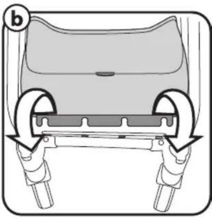
natural_image
Diagram of a car seat assembly with two wheels and a seat cover (no text or symbols)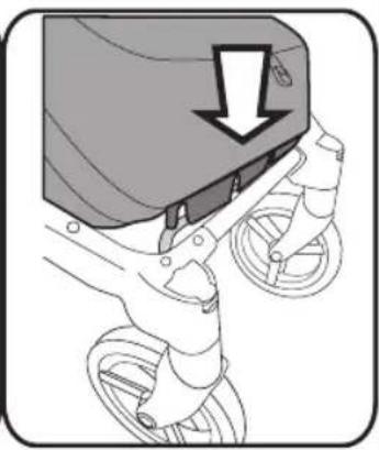
natural_image
Diagram of a bicycle's seatbelt mechanism with a downward arrow indicating force or motion (no text or symbols present)5
©
natural_image
Technical diagram showing a mechanical component with an inset close-up of a jacket's seat and adjustment mechanism (no text or symbols)6
d
natural_image
Illustration of a stroller with wheels and a shaded seat, no text or symbols present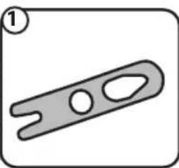
natural_image
Simple line drawing of a mechanical clamp or lever (no text or symbols)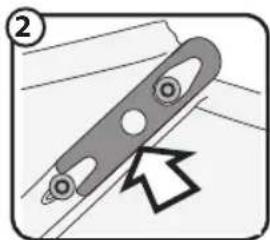
natural_image
Diagram of a mechanical component with a curved handle and circular holes, showing an arrow pointing to a section (no text or symbols present)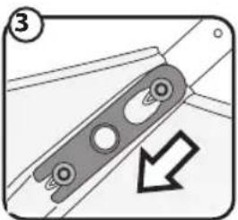
natural_image
Mechanical component diagram showing a bracket with mounting holes and a downward arrow indicating direction (no text or symbols)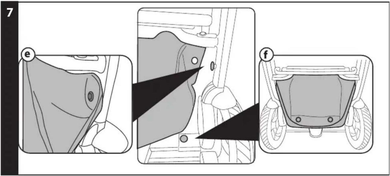
10
11
natural_image
Diagram showing a vehicle on a road with directional arrows indicating motion (no text or symbols)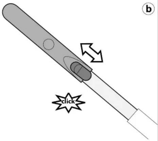
12
natural_image
Line drawing of a wheeled vehicle chassis with two wheels and a connecting rod, no text or symbols present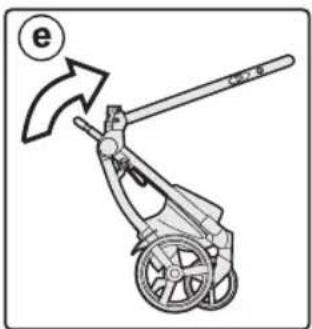
natural_image
Diagram of a mechanical device with a lever and wheels, showing an arrow indicating motion (no text or symbols present)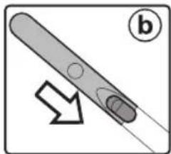
natural_image
Diagram of a pen-like object with a circular end and arrow indicating direction (no text or symbols)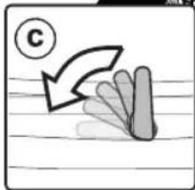
natural_image
Simple line drawing of a hand holding a leaf with a curved arrow and a circled number C (no text or symbols)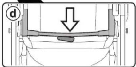
13
14
natural_image
Technical line drawing of a mechanical device with a wheel and lever, showing motion direction (no text or symbols)15

16
17
natural_image
Technical line drawing of a vehicle chassis frame with labeled components and directional arrows indicating movement (no text or symbols present)1
SEAT
2
natural_image
Technical illustration of a mechanical clamp tool with a downward arrow indicating motion (no text or symbols present)a
3
natural_image
Technical line drawing of a mechanical device with lever and handle (no text or symbols)a
natural_image
Technical line drawing of a mechanical clamp or lever mechanism (no text or symbols)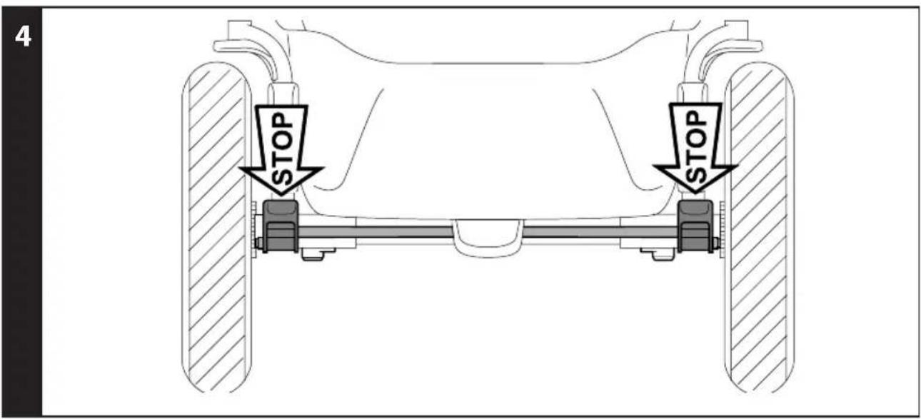
8
a
natural_image
Diagram of a car seatbelt with directional arrows indicating steering wheel movement (no text or symbols)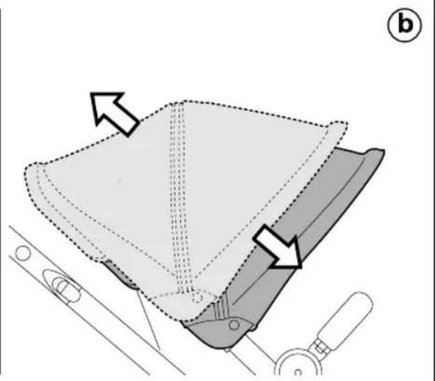
natural_image
Diagram of a mechanical component with arrows indicating direction, no text or symbols present9
13
14
15
16
natural_image
Illustration of a stroller with a hand pointing to the front wheel (no text or symbols)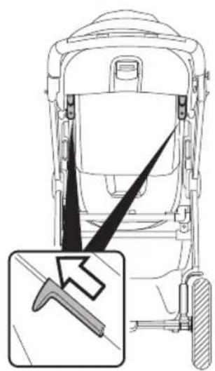
natural_image
Diagram of a vehicle rear view showing steering wheel, dashboard, and gear mechanism (no text or symbols)b
natural_image
Illustration of a stroller with fan blades and wheels, showing motion direction (no text or symbols)©
17
natural_image
Illustration of a mechanical device with directional arrows indicating motion (no text or symbols)b
natural_image
Line drawing of a mechanical device with an upward arrow and circled number ① (no text or symbols on the device itself)18
natural_image
Line drawing of a stroller with wheels and a stick, featuring a starburst labeled 'click' (no text or symbols on the device itself)b
natural_image
Illustration of a stroller with floral blades and a starburst symbol labeled 'click' (no text or symbols on the diagram itself)19
natural_image
Abstract diagram with curved arrow and shaded segments on lined paper (no text or symbols)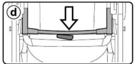
natural_image
Diagram of a pen-like object with a circular end and an arrow pointing to it, labeled 'b' (no text or symbols on the object itself)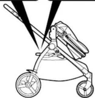
natural_image
Line drawing of a stroller with wheels and a blade, no text or symbols present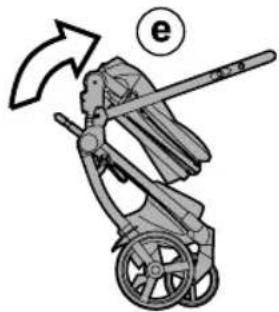
natural_image
Illustration of a person in a stroller with a handrail and arrow indicating rotation (no text or symbols)20
21
natural_image
Technical line drawing of a mechanical device with a wheel and lever, showing no text or symbols22
23
natural_image
Technical line drawing of a car seat assembly with a magnified inset showing internal components (no text or symbols)24
natural_image
Line drawing of a seatbelt device with two connectors and a close-up inset showing a cable being inserted (no text or symbols)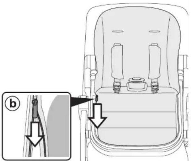
25

natural_image
Line drawing of a stroller with wheels and a close-up inset showing a rectangular object with a diagonal line (no text or symbols)26
a
27
natural_image
Technical line drawing of a mechanical device showing front and side views (no text or symbols)Ypsi Chassis
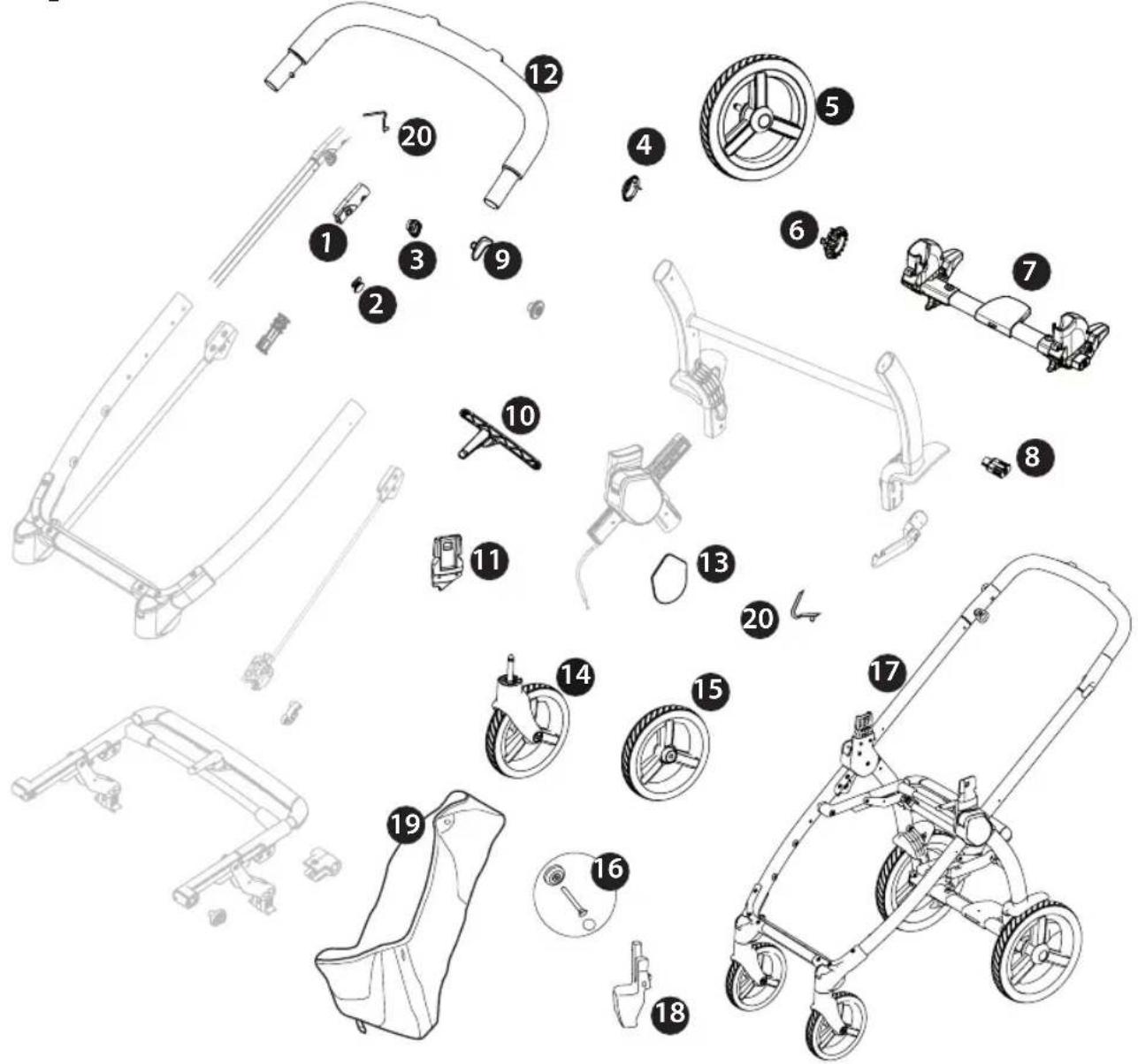
1 SPST7924DN
SPST7924SN
2 SPST7936N
3 SPST7935N
4 SPST6232KN
5 SAPI10219NGP
6 SPST7255N
7 ARPI0730L89NGR
8 SPST7309N
9 SPST7925N
10 SAPI10405NGR
11 SPST10252DN
SPST10252SN
12 SAPI0696.
13 SPST7286XXDNPEG
SPST7286XXSNPEG
14 SAPI10218NGP
15 SAPI7956KNN
16 MMST0087N
SPST7303N
MMRA0007
MMCA0007L30
17 ITCYP00BXNL25·
18 SAPI10260DNF
SAPI10260SNF
19 ERSHYP00-SH01RT01
20 MMMO0025D
EN Spare parts available in different colours to be specified when ordering.
1 ITSE050000NL25
2 ASPI0225L89N
3 BSPSYP.
4 BCASYP.
5 SAPI10231.
6 BSASYP.
EN\_English
Thank you for choosing a Peg-Pérego product.
WARNING
- CAREFULLY READ INSTRUCTIONS AND KEEP FOR FUTURE USE. - THE CHILD'S SAFETY COULD BE PUT AT RISK IF THE INSTRUCTIONS ARE NOT FOLLOWED.
- THIS PRODUCT IS DESIGNED FOR CHILDREN WHOSE MAXIMUM WEIGHT IS 50 lbs (22.7 KG) AND WHOSE MAXIMUM HEIGHT IS 43 INCHES (110 CM). THIS SHOPPER BASKET IS DESIGNED TO CARRY A MAXIMUM WEIGHT OF 15 POUNDS (7 KG). ANY POACH OR POCKET PROVIDED WITH THIS UNIT IS DESIGNED TO CARRY A MAXIMUM WEIGHT OF 0.44 lbs (0.2 KG). THIS ITEM WAS DESIGNED FOR USE IN COMBINATION WITH 1 PEG-PÉREGO PRIMO VIAGGIO 4·35 NIDO CAR SEAT, PRIMO VIAGGIO 4·35 CAR SEAT, Z4 SEAT.
BEFORE USE CHECK THAT THE CAR SEAT OR SEAT UNIT ARE CORRECTLY FIXED TO THE ITEM.
- DO NOT PUT HOT DRINKS IN THE DRINKHOLDER, NOR ITEMS WEIGHING MORE THAN 0.5 KG (1 LBS).
WARNING: THE
MAXIMUM WEIGHT ALLOWED TO HANG FROM THE HANDLEBAR IS 2,2 LBS (1 KG)
WARNING: DO
NOT APPLY GREATER WEIGHTS TO THE HANDLEBAR THAN THOSE SPECIFIED BY THE MANUFACTURER SO AS NOT TO COMPROMISE THE STABILITY AND SAFETY OF THE PRODUCT
- FAILURE TO FOLLOW MANUFACTURER'S SPECIFICATIONS OR USE OF ACCESSORIES OTHER THAN THOSE APPROVED BY THE MANUFACTURER MAY CAUSE THE UNIT TO BECOME UNSTABLE.
WARNING: AVOID
SERIOUS INJURY FROM FALLING OR SLIDING OUT. ALWAYS USE COMPLETE 5
POINT SEAT BELT IN COMBINATION WITH THE SEAT UNIT.
WARNING: NEVER
LEAVE YOUR CHILD UNATTENDED.
- DO NOT USE THE PRODUCT IF IT HAS BROKEN OR MISSING PARTS.
- DO NOT USE NEAR FIRE OR EXPOSED FLAME.
WARNING: KEEP
CHILDREN AWAY WHILE OPENING AND CLOSING TO AVOID TRAPPING OR INJURY
WARNING:
WARNING! DO NOT ADD ANY MATTRESS ARE NOT APPROVED BY THE MANUFACTURER.
WARNING: DO
NOT MAKE ANY ALTERATIONS OR MODIFICATIONS TO THE STROLLER WITH PRODUCTS NOT SUPPLIED BY THE MANUFACTURER AS THIS MAY CAUSE INSTABILITY OR STRUCTURAL DEMAGE NOT COVERED UNDER WARRANTY.
NOTICE
THIS ARTICLE MEETS OR EXCEEDS ALL REQUIREMENTS COVERED IN ASTM F833 STANDARD AND LATEST REVISIONS.
The images referring to the textile details may differ from the collection purchased.
For more information, consult our website: www.pegperego.com
CHASSIS:
INSTRUCTIONS
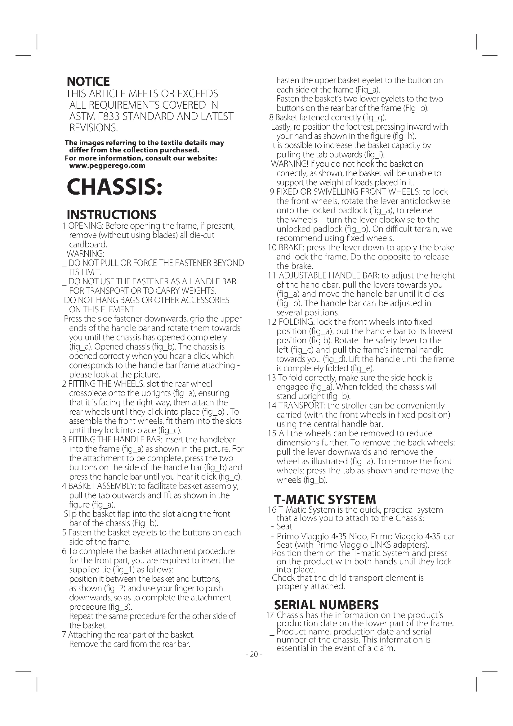
1 OPENING: Before opening the frame, if present, remove (without using blades) all die-cut cardboard.
WARNING:
- DO NOT PULL OR FORCE THE FASTENER BEYOND ITS LIMIT.
_ DO NOT USE THE FASTENER AS A HANDLE BAR FOR TRANSPORT OR TO CARRY WEIGHTS. DO NOT HANG BAGS OR OTHER ACCESSORIES ON THIS ELEMENT.
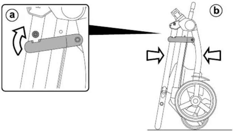
Press the side fastener downwards, grip the upper ends of the handle bar and rotate them towards you until the chassis has opened completely (fig_a). Opened chassis (fig_b). The chassis is opened correctly when you hear a click, which corresponds to the handle bar frame attaching - please look at the picture.
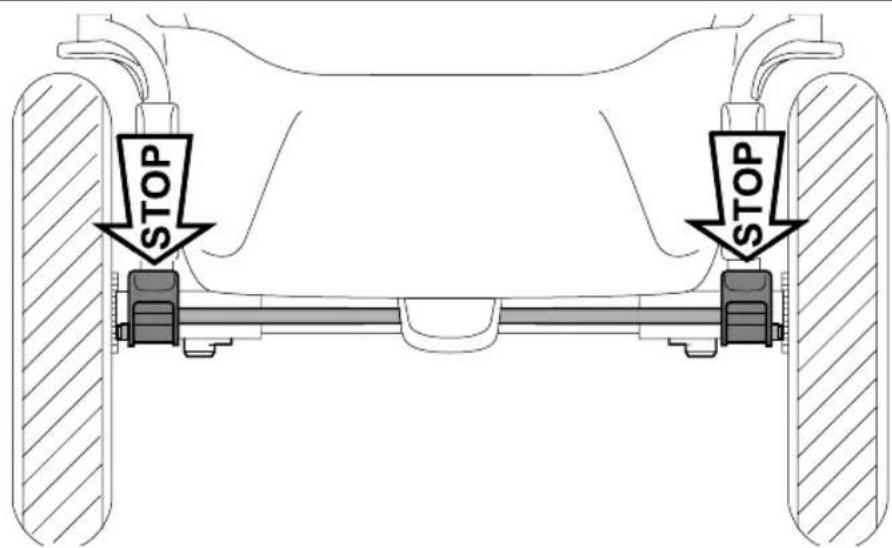
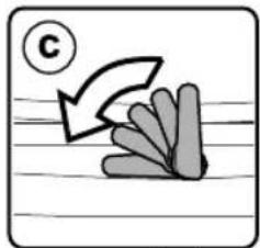
2 FITTING THE WHEELS: slot the rear wheel crosspiece onto the uprights (fig_a), ensuring that it is facing the right way, then attach the rear wheels until they click into place (fig_b). To assemble the front wheels, fit them into the slots until they lock into place (fig_c).
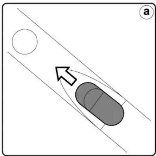
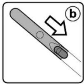
3 FITTING THE HANDLE BAR: insert the handlebar into the frame (fig_a) as shown in the picture. For the attachment to be complete, press the two buttons on the side of the handle bar (fig_b) and press the handle bar until you hear it click (fig_c).
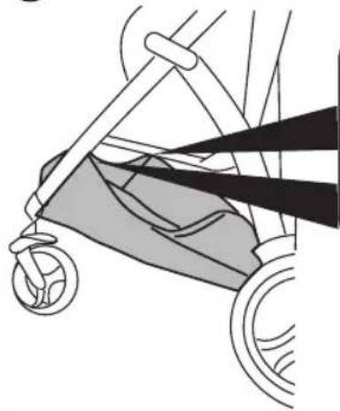
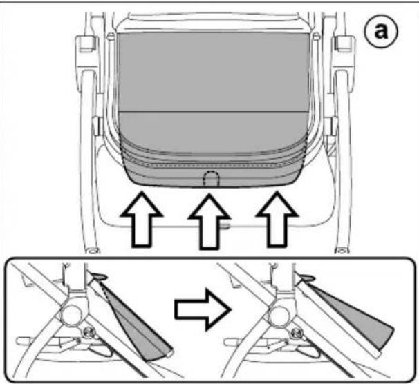
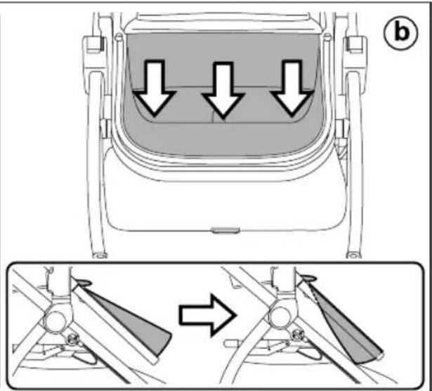
4 BASKET ASSEMBLY: to facilitate basket assembly, pull the tab outwards and lift as shown in the figure (fig_a).
Slip the basket flap into the slot along the front bar of the chassis (Fig_b).
5 Fasten the basket eyelets to the buttons on each side of the frame.
6 To complete the basket attachment procedure for the front part, you are required to insert the supplied tie (fig_1) as follows: position it between the basket and buttons, as shown (fig_2) and use your finger to push downwards, so as to complete the attachment procedure (fig_3). Repeat the same procedure for the other side of the basket.
7 Attaching the rear part of the basket. Remove the card from the rear bar.
Fasten the upper basket eyelet to the button on each side of the frame (Fig_a).
Fasten the basket's two lower eyelets to the two buttons on the rear bar of the frame (Fig_b).
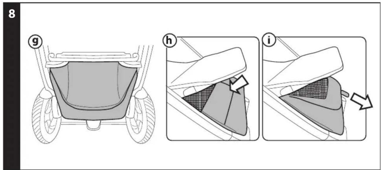
8 Basket fastened correctly (fig_g).
Lastly, re-position the footrest, pressing inward with your hand as shown in the figure (fig_h).
It is possible to increase the basket capacity by pulling the tab outwards (fig_i).
WARNING! If you do not hook the basket on correctly, as shown, the basket will be unable to support the weight of loads placed in it.
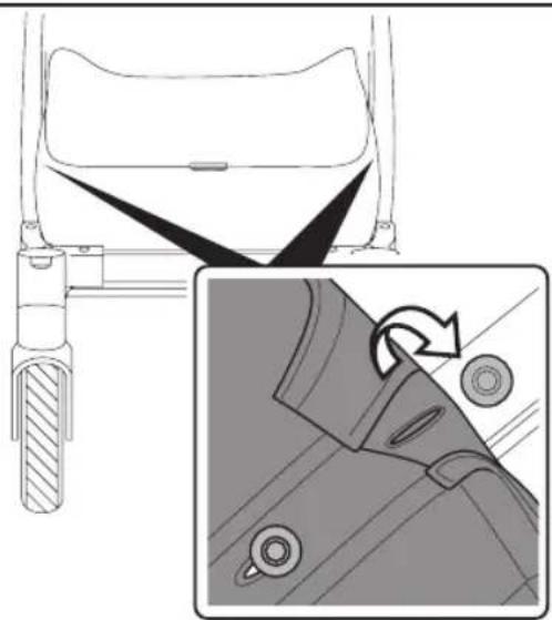
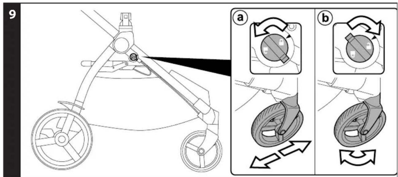
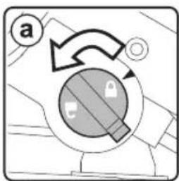
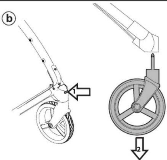
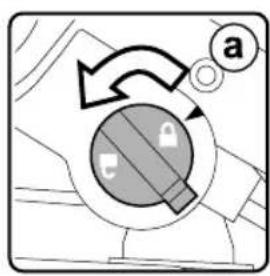
9 FIXED OR SWIVELLING FRONT WHEELS: to lock the front wheels, rotate the lever anticlockwise onto the locked padlock (fig_a), to release the wheels - turn the lever clockwise to the unlocked padlock (fig_b). On difficult terrain, we recommend using fixed wheels.
10 BRAKE: press the lever down to apply the brake and lock the frame. Do the opposite to release the brake.
11 ADJUSTABLE HANDLE BAR: to adjust the height of the handlebar, pull the levers towards you (fig_a) and move the handle bar until it clicks (fig_b). The handle bar can be adjusted in several positions.
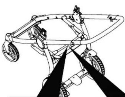
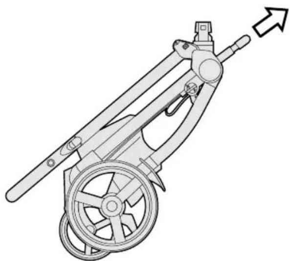
12 FOLDING: lock the front wheels into fixed position (fig_a), put the handle bar to its lowest position (fig b). Rotate the safety lever to the left (fig_c) and pull the frame's internal handle towards you (fig_d). Lift the handle until the frame is completely folded (fig_e).
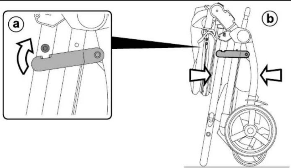
13 To fold correctly, make sure the side hook is engaged (fig_a). When folded, the chassis will stand upright (fig_b).
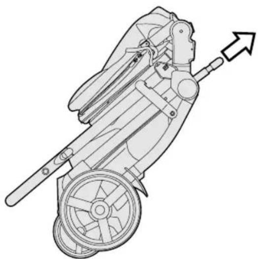
14 TRANSPORT: the stroller can be conveniently carried (with the front wheels in fixed position) using the central handle bar.
15 All the wheels can be removed to reduce dimensions further. To remove the back wheels: pull the lever downwards and remove the wheel as illustrated (fig_a). To remove the front wheels: press the tab as shown and remove the wheels (fig_b).
T-MATIC SYSTEM
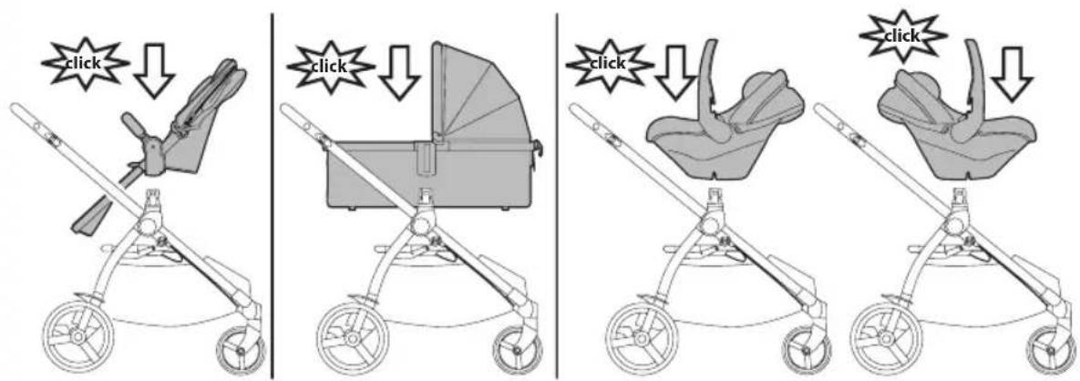
16 T-Matic System is the quick, practical system that allows you to attach to the Chassis:
- Seat
- Primo Viaggio 4•35 Nido, Primo Viaggio 4•35 car Seat (with Primo Viaggio LINKS adapters).
Position them on the T-matic System and press on the product with both hands until they lock into place.
Check that the child transport element is properly attached.
SERIAL NUMBERS
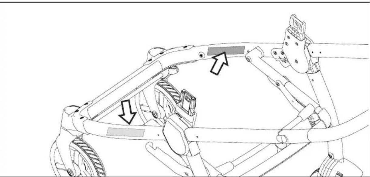
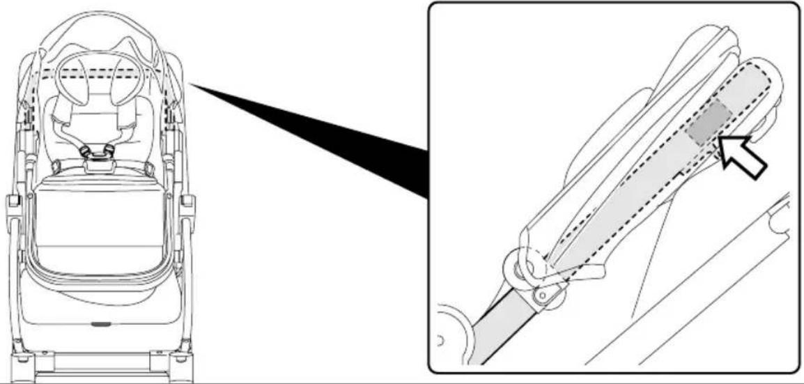
17 Chassis has the information on the product's production date on the lower part of the frame.
- Product name, production date and serial number of the chassis. This information is essential in the event of a claim.
CLEANING AND MAINTENANCE
Cleaning must only be carried out by adults. PRODUCT MAINTENANCE: protect from the weather: water, rain, or snow; prolonged and continuous exposure to bright sunlight may give rise to colour changes of various different materials; store this product in a dry place. CLEANING THE CHASSIS: periodically clean all plastic parts with a damp cloth. Do not use solvent or similar cleaning products; keep all metal parts dry to prevent rusting; keep moving parts clean (adjustment mechanisms, locking mechanisms, wheels, ...) and free of dust and sand and, if necessary, lubricate with light machine oil.
SEAT:
INSTRUCTIONS
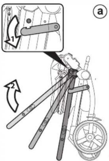
1 OPENING: Before opening the Seat, remove (without using blades) any die-cut cardboard. Open the seat from the ends, pulling until it clicks.
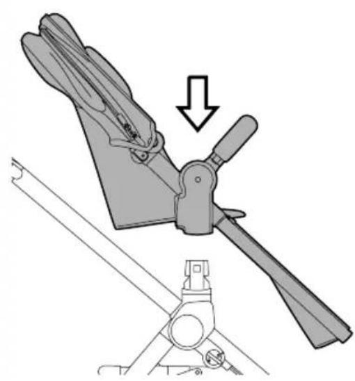
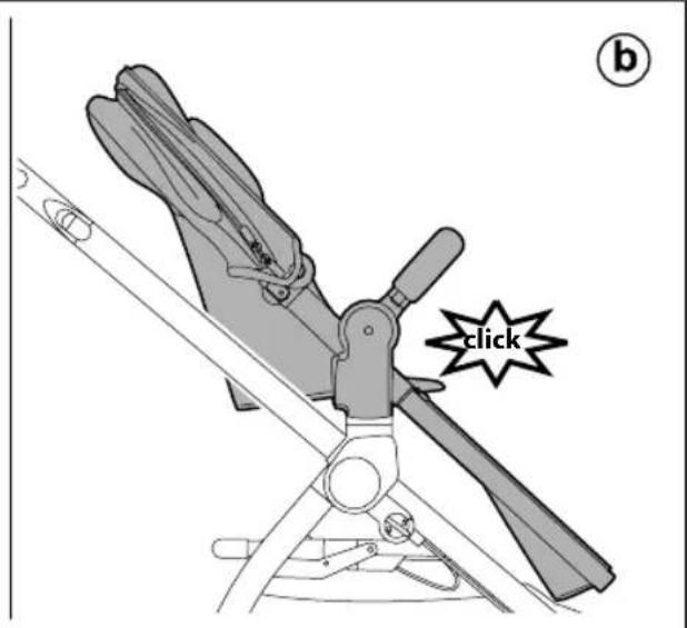
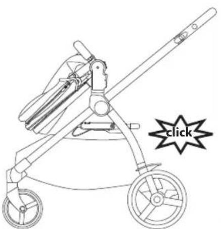
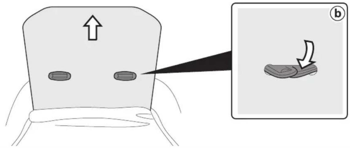
2 ATTACHING THE SEAT ONTO THE CHASSIS: To fasten the Seat, position it on the chassis (fig_a) and press down with both hands until it clicks (fig_b).
Ensure the Seat is properly attached.
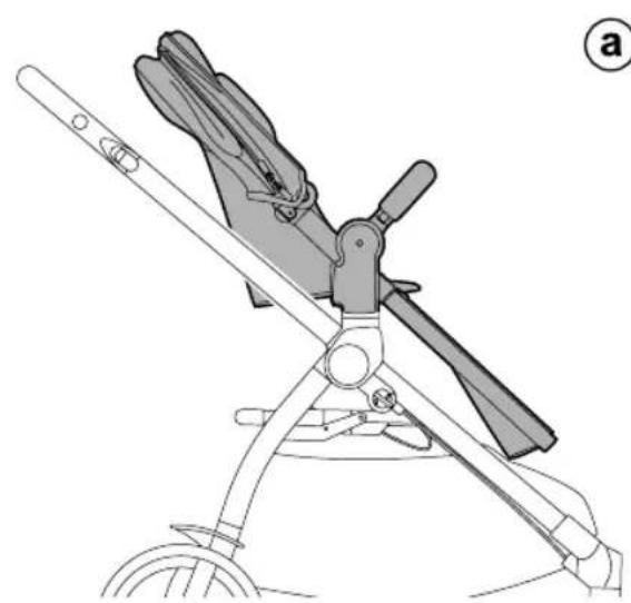
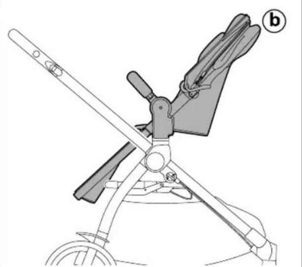
3 The Seat can be attached onto the chassis in "world-facing" (fig_a) or "mum-facing" position (fiq_b).
4 Always engage the brake on the chassis before fastening and unfastening the seat.
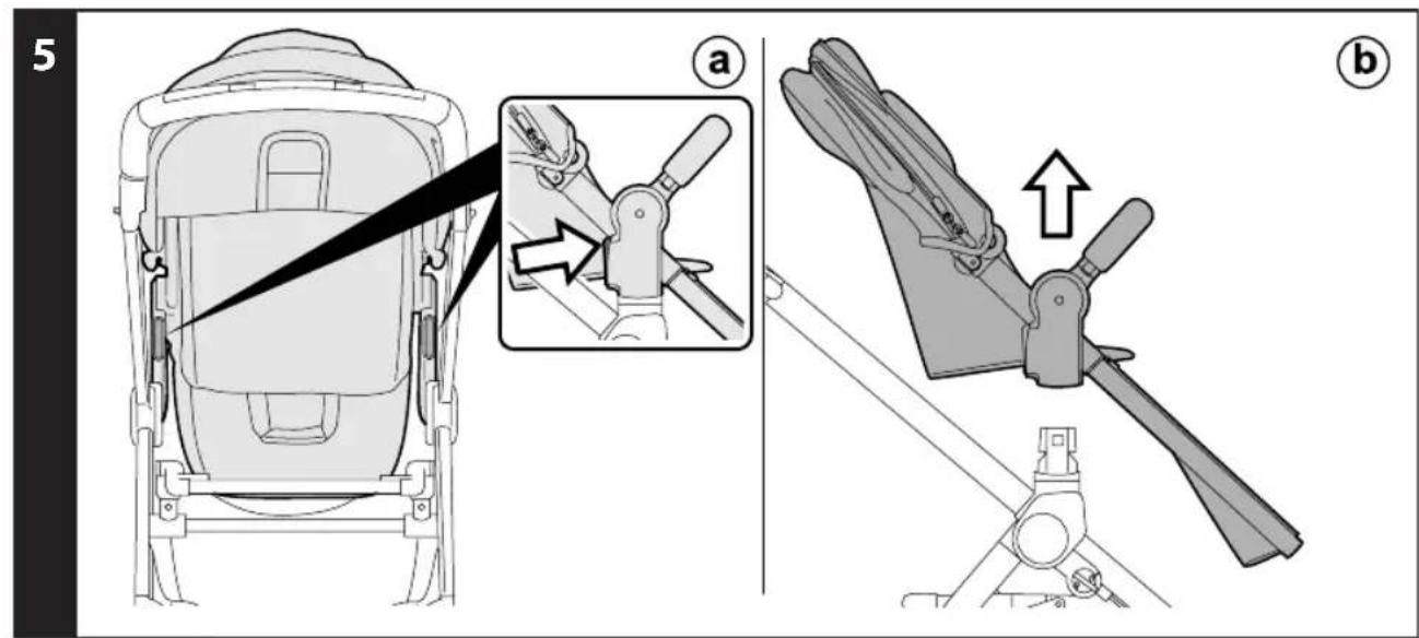
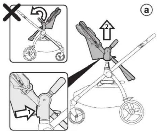
5 REMOVING THE YPSI SEAT FROM THE CHASSIS: To unfasten the Seat, press the levers near the chassis attachments (fig_a) and lift the seat at the same time (fig_b).
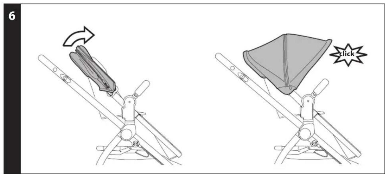
6 HOOD: to use the hood, stretch it until it clicks (so it is completely open).
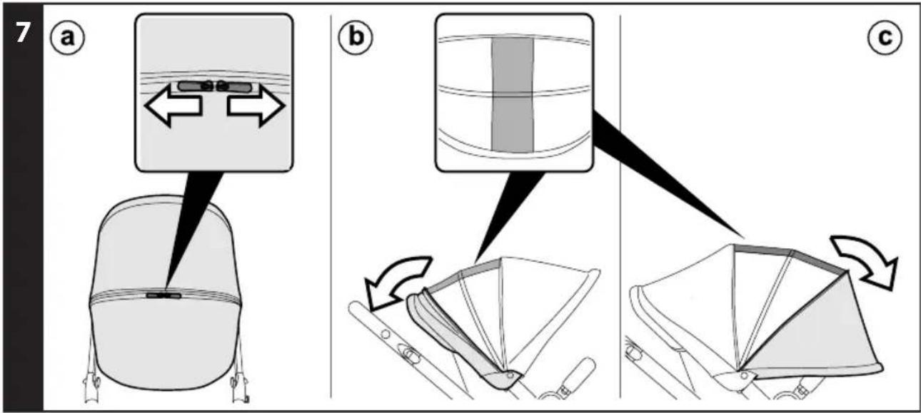
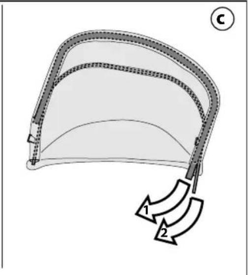
7 The hood comes with a mesh insert so that the baby can be seen from any position. To use it, open the zips (fig_a) and slide the hood's insert backwards (fig_b). Alternatively, the hood can be stretched further forwards (fig_c).
8 Sliding the hood's attachments on the uprights (fig_a), you can vary its distance from the seat (fig_b).
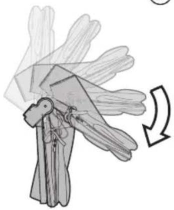
9 ADJUSTING THE LEG REST: To switch from "sitting" to "lying" or vice versa, simply press on the leg rest to obtain the configuration you wish.
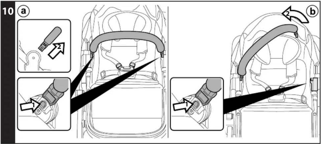
10 FRONT BAR: The front bar can be removed by pushing the buttons on the sides (fig_a), or it can be opened on one side pressing one button only (fiq_b).
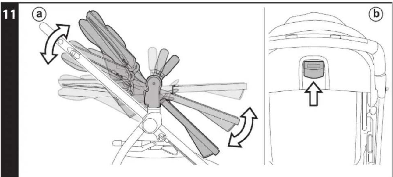
11 BED POSITION: the seat can be adjusted in three positions, from "sitting" to "lying", with an intermediate position (fig_a). To switch from one position to another, pull the lever shown in the picture (fiq_b).
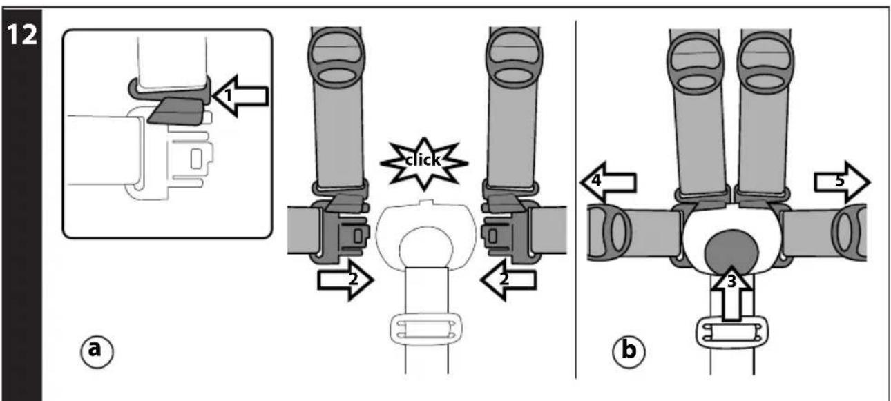
12 5-POINT SAFETY HARNESS: to fasten, insert the two buckles into the waist strap (with the straps attached in the crotch strap) until you hear a click (fig_a). To unfasten them, press the button which is situated at the centre of
the seatbelt buckle and pull the waist strap outwards (fig_b).
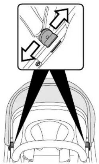
13 To tighten the waist strap, pull on both sides in the direction of the arrow; to loosen it, do the opposite.
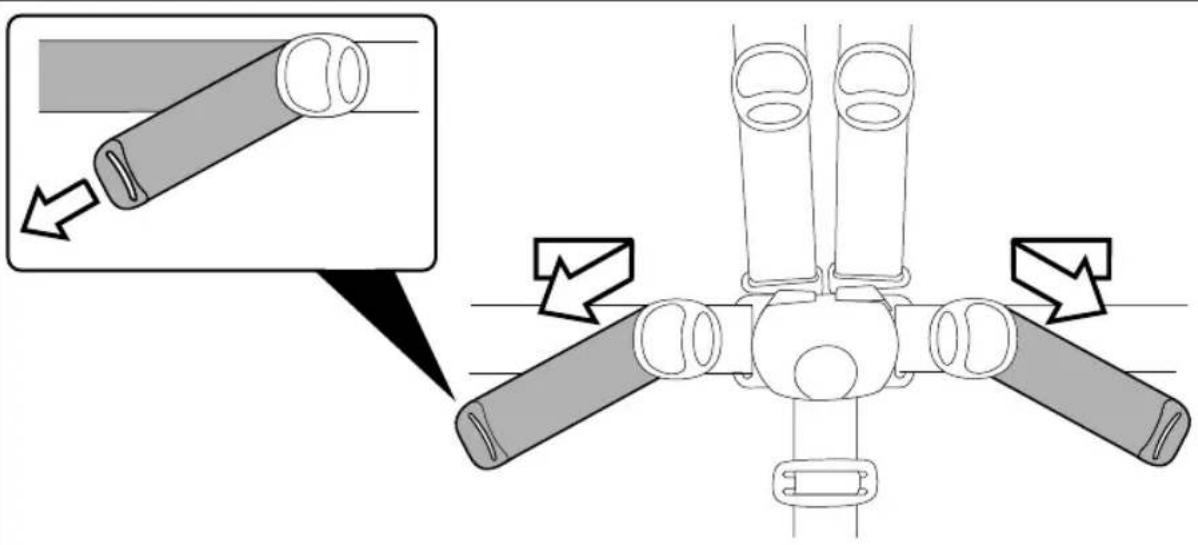
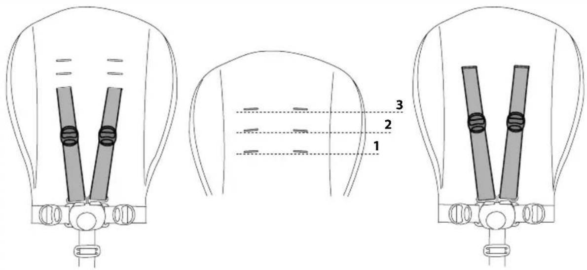
14 The safety harness can be adjusted in 3 positions according to the child's height. You must use the higher positions as the child grows bigger.
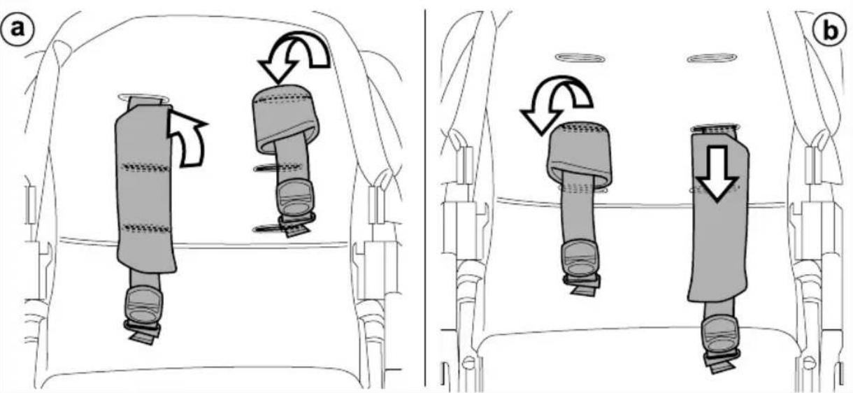
15 Adjust the height, inserting the straps with shoulder pads through the eyelet in the backrest (fig_a) and pull them through the desired eyelets (fig b).
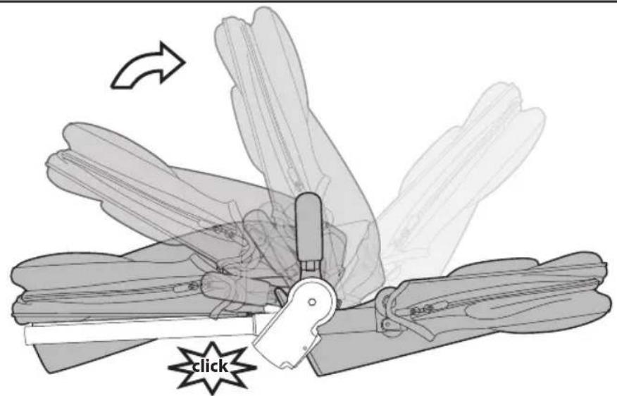
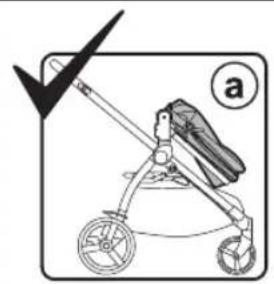
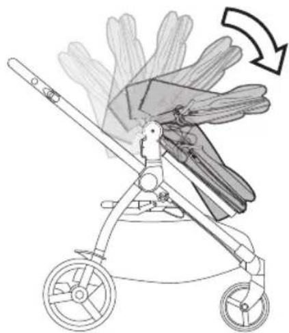
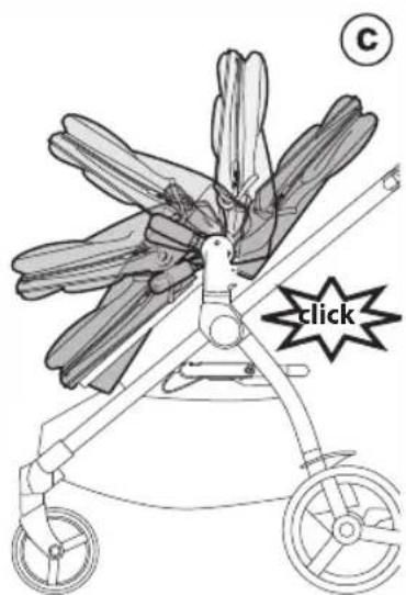
16 FOLDING THE SEAT ATTACHED ONTO THE CHASSIS: the Seat can be folded attached on the chassis only in world-facing position (fig_a). To do this:
- the leg rest must be in "sitting" position,
- fold down the hood,
- pull the levers on the up-right (fig_b) - fold Seat onto itself (fig_c).
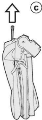
17 WARNING: If Seat is in mum-facing position, it must be unfastened before folding (fig_a). It can take up less room when folded (fig_b) and can be conveniently carried using the supplied handle (fig_c).
18 OPENING THE CHASSIS WITH SEAT ATTACHED:
Press the side attachment fastener downwards, grip the upper ends of the handle bar and rotate them towards you until the chassis opens completely (fig_a). Chassis open (fig_b). A "click" sound means it has opened correctly and corresponds to the attachment onto the base. Next, open the Ypsi Seat from the ends, pulling it until it clicks (fig_c).
19 FOLDING THE CHASSIS WITH SEAT ATTACHED: put the front wheels in locked position (fig_a), lower the handle bar to the lowest position (fig_b). Rotate the safety lever to the left (fig_c) and, at the same time, pull the frame's internal handle bar towards you (fig_d).
Lift the handle bar until the frame is completely folded (fig_e).
WARNING: If the seat is mum-facing it cannot be folded attached onto the chassis. It must be unfastened.
20 To fold correctly, check the side fastener is engaged (fig_a). If it has not engaged automatically, compress the frame slightly. The folded stroller is free-standing (fig_b).
21 TRANSPORT: the stroller can be conveniently carried (with the front wheels in locked position) using the central handle.
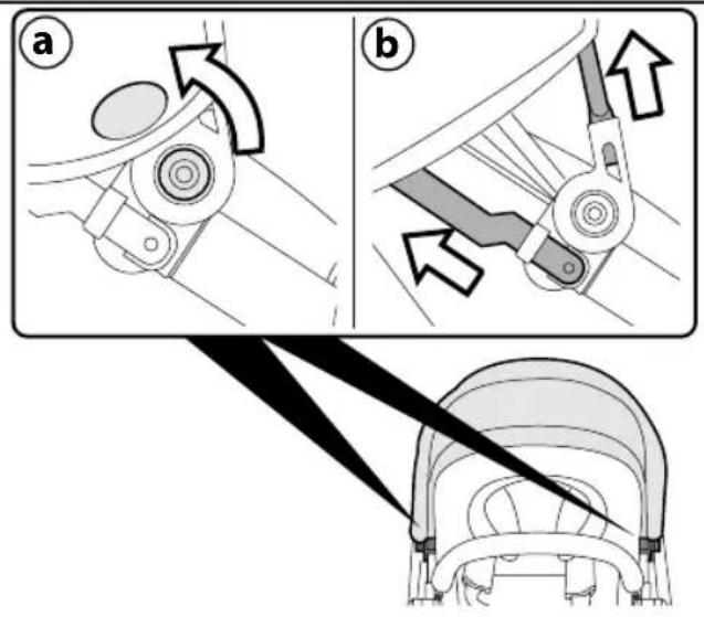
22 REMOVING THE SOFT COVER: to remove the hood cover, unfasten the 2 buttons near the pivots (fig_a), then press the buttons on the two attachments and remove the hood (fig_b). Lastly, extract the two rigid supports (fig_c).
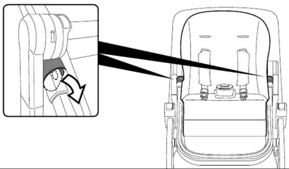
23 To remove the soft cover from the seat, undo the straps on the side of frame.
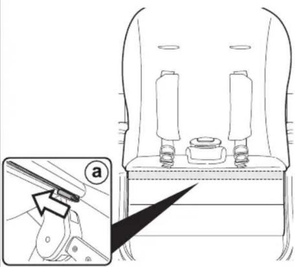
24 Open the zip that attaches the sack to the horizontal bar (fig_a) and open the zip along the frame (fig_b), then remove the sack.
25 Remove the metal rod from the back of the leg rest.
26 To remove the sack, remove the rigid panel from the back until you can see the eyelets through which the belt ends pass (fig_a); insert those ends in the eyelets so that the belts
can be separated from the plate and the sack removed (fig_b).
T-MATIC SYSTEM
T-Matic System is the quick, practical system that allows you to attach the Seat to the Chassis, thanks to the practical T_Matic attachments.
SERIAL NUMBERS
27 Information about the production date can be found on the Seat.
_ The product name, production date and serial number of the chassis.
This information is required for any complaints.
CLEANING AND MAINTENANCE
Cleaning must only be carried out by adults. PRODUCT MAINTENANCE: protect from the weather: water, rain, or snow; prolonged and continuous exposure to bright sunlight may give rise to colour changes of various different materials; store this product in a dry place.
CLEANING THE SEAT: periodically clean all plastic parts with a damp cloth. Do not use solvent or similar cleaning products; keep all metal parts dry to prevent rusting; keep moving parts clean (adjustment mechanisms, locking mechanisms, wheels, ...) and free of dust and sand and, if necessary, lubricate with light machine oil.
CLEANING FABRIC PARTS: Brush the fabric parts to remove dust.
- When washing, closely follow the instructions stated on the label sewn into the cover.
- Do not use chlorine bleach.
- Do not iron.
- Do not dry clean.
- Do not remove stains with solvents.
- Do not tumble dry.
Peg-Perego accessories are designed as a useful, practical means of simplifying the lives of parents. Discover all your product's accessories on www.pegperego.com
PEG-PÉREGO S.p.A.
Peg Pérego can make changes at any time to the models described in this publication for technical or commercial reasons.
PEG-PÉREGO
AFTER-SALES SERVICE
If any parts of the item get lost or damaged, only use genuine Peg Pérego spare parts. For any repairs, replacements, information on the products and sales of genuine spare parts and accessories, contact the Peg Pérego Assistance Service and state the serial number of the product, if present.
USA
tel. 800.671.1701
fax 260.471.6332
call us toll free 1.800.671.1701
website www.pegperego.com
CANADA
tel. 905.839.3371
fax 905.839.9542
call us toll free 1.800.661.5050
website www.pegperego.com
ES\_Español
call us toll free 1.800.671.1701
website www.pegperego.com
FR\_Français
call us toll free 1.800.661.5050
site Internet www.pegperego.com
EN\_English
Declaration of conformity

WARNING
AVOID SERIOUS INJURY FROM FALLING OR SLIDING OUT. ALWAYS USE COMPLETE 5 POINT SEAT BELT.
ADVERTENCIA
FIBX1801I274