IDS 100 - Heating TROTEC - Free user manual and instructions
Find the device manual for free IDS 100 TROTEC in PDF.
User questions about IDS 100 TROTEC
0 question about this device. Answer the ones you know or ask your own.
Ask a new question about this device
Download the instructions for your Heating in PDF format for free! Find your manual IDS 100 - TROTEC and take your electronic device back in hand. On this page are published all the documents necessary for the use of your device. IDS 100 by TROTEC.
USER MANUAL IDS 100 TROTEC
- Notes on how to use the manual.. A-1 Legend .A-1
- Scope of delivery A-1
- Guarantee provisions.. A-1
- General safety instructions A-2
- Function and product characteristics A-2
- Technical data A-2 Fuels .A-3
- Proper and improper use A-3
Proper use .A-3
Improper use .A-3 - Installation conditions.. A-3
- Description of device A-3 Oil heating unit .A-3 Control panel .A-3
- Installation and commissioning.. A-4
11.Exhaust system .A-4 Chimney duct. .A-4 Wall duct. .A-4 - Functions and operation A-4
Switching on the oil heating unit A-4
Switching off the oil heating unit A-5
Resuming operation after a failure A-5
Safety equipment A-5 - Transport A-6
- Care and maintenance.. A-6 Cleaning after every 50 operating hours .A-6 Cleaning the oil heating unit. .A-6
- Disposal .A-6 Oil heating unit .A-6 Heating oil .A-6 Packaging .A-6
- Service and repair A-6
- Troubleshooting A-6
- Appendix A-9
Circuit diagram A-9
Setting of the air setting ring A-9
1. Notes on how to use the manual
This operating manual contains all important information required for a safe commissioning and use of your oil heating unit.
It provides you with support for operating the device and remedying possible problems as well as with information on disposal and customer service.
Please read this manual thoroughly and completely before using the oil heating unit for the first time.
Please store this operating manual and keep it within reach in order to consult it if necessary.
Please observe all safety instructions and information on use and maintenance contained in this manual.
This manual should be attached to the device if the latter is made available to other persons for use.
Legend
WARNING SYMBOL. This symbol is followed by a hazard warning which contains instructions whose non-compliance may cause serious injuries and/or death and/or property damage.

Additional information which might be helpful when using the device.
2. Scope of delivery
The scope of delivery of the oil heating unit includes:
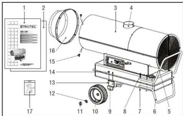
1 Operating manual 10 Wheel 2x
2 Assembly instruction manual 11 Locking pin 2x
3 Oil heating unit ISD 100 12 Spacer ring 2x
4 Chimney connection 150 mm 13 Hexagon nut 4x
5 Handle 14 Hexagon screw 4x
6 Support 15 Screw 4x
7 Hexagon nut 4x 16 Outlet cone
8 Hexagon screw 4x 17 Assembly tools
9 Support bracket for axis
3. Guarantee provisions
The warranty period granted for the oil heating unit IDS 100 shall be 12 months.
Any damage to the device resulting from non-compliance with the instructions contained in this manual shall be excluded from the guarantee. The manufacturer shall assume no liability for damages to the device and/or its accessories that are caused by unauthorised modifications.
For any further terms of guarantee, please refer to the General Terms and Conditions (GTC), which are available on our website: www.trotec.de.
4. General safety instructions

Please observe the following safety instructions! Any non-compliance with these instructions may have serious consequences for the health of persons and could result in property damage and damage to the environment.
Risk of explosion!
- Do not operate the device in potentially flammable or explosive environments. Do not install it in such environments, either.
- Do not place the device on a flammable surface.
- Remove any inflammable materials and chemicals from the immediate operating environment.
Functional impairment of and damage to the device!
Do not use the device outdoors.
Install the device in a stable position.
- Keep the intake and exhaust openings free.
- Do not cover the device during operation.
- Only disconnect the device from the mains once it has cooled down completely.
- Do not use any chemicals for cleaning the device.
Risk of injury and damage to property due to defective devices!
- Before each use of the device, check its accessories and connection parts for possible damages. Do not use any defective devices or device parts.
- Do not use the device if you detect any damage to its plug and cables. Defective power cables represent a serious health threat.
Danger to life through electrical shock!
- Only connect the device to power sources that are in good technical order. Do not use damaged wall outlets!
- Pull the connection cable out of the wall outlet by pulling it at its plug.
- Do not touch electrical connection cables when your hands are wet!
- Protect the electrical connection cables against damage caused by, for example, animals.
- Do not carry out any changes or repairs on the device!
- Do not expose the device to any liquids.
- Do not apply any liquids to the interior of the device. If this does happen nevertheless, pull out the power cord and have the device checked by a specialist workshop.
Risk of injury!
- Do not insert any objects into the intake and exhaust opening of the device.
- Do not reach into the existing openings.
- Do not leave children or animals unattended near the operating device!
-
Do not operate the device in rooms with insufficient supply of combustion air.
-
Avoid the improper use of fuels.
Risk of environmental pollution!
- Do not let any leaked fuel seep away into the soil and prevent it from entering the sewer system.
5. Function and product characteristics
The oil heating unit IDS 100 is used to heat up room air in order to achieve a fast heating of large rooms.
The oil heating unit is operated with heating oil. The device features an indirect combustion and is provided with an exhaust connection in order to discharge the exhaust gas via the chimney.
A selection of two operating modes ensures that the oil heating unit can be controlled both manually by the user as well as automatically with the support of the thermostat.
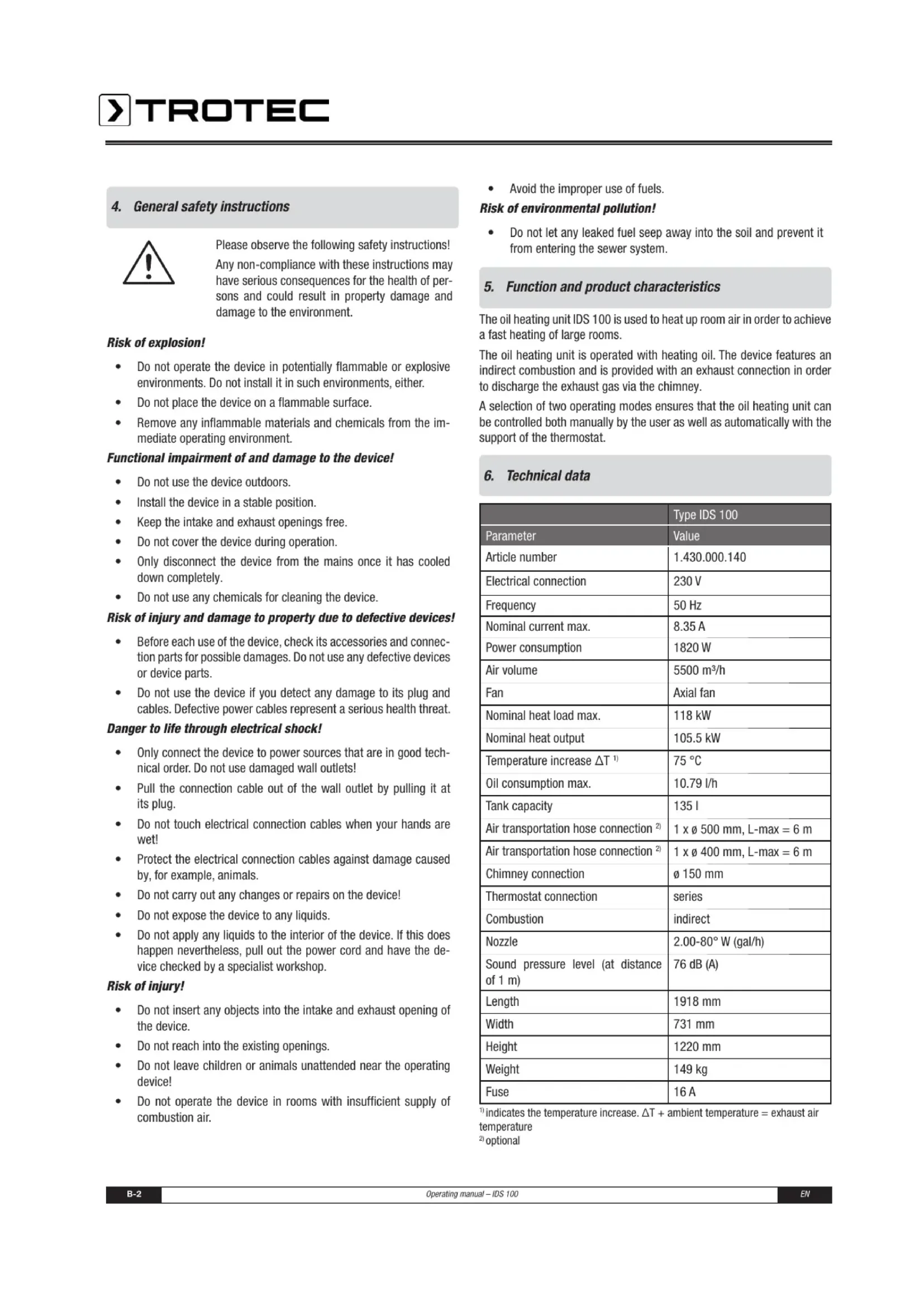
6. Technical data
| Type IDS 100 | |
| Parameter | Value |
| Article number | 1.430.000.140 |
| Electrical connection | 230 V |
| Frequency | 50 Hz |
| Nominal current max. | 8.35 A |
| Power consumption | 1820 W |
| Air volume | 5500 m³/h |
| Fan | Axial fan |
| Nominal heat load max. | 118 kW |
| Nominal heat output | 105.5 kW |
| Temperature increase ΔT¹) | 75 °C |
| Oil consumption max. | 10.79 l/h |
| Tank capacity | 135 l |
| Air transportation hose connection²) | 1 x ø 500 mm, L-max = 6 m |
| Air transportation hose connection²) | 1 x ø 400 mm, L-max = 6 m |
| Chimney connection | ø 150 mm |
| Thermostat connection | series |
| Combustion | indirect |
| Nozzle | 2.00-80° W (gal/h) |
| Sound pressure level (at distance of 1 m) | 76 dB (A) |
| Length | 1918 mm |
| Width | 731 mm |
| Height | 1220 mm |
| Weight | 149 kg |
| Fuse | 16 A |
indicates the temperature increase. T + ambient temperature = exhaust air temperature
^20 optional
Fuels
The following fuels have been approved for use with the oil heating unit IDS 100: heating oil EL, diesel
7. Proper and improper use
Proper use
The oil heating unit IDS 100 has been developed for the generation of hot air and may be used indoors and in roofed outdoor areas.
The device can be used for heating large rooms such as storerooms, workshops, building sites, greenhouses or cowsheds. It has been designed for stationary operation without frequently changing locations. The oil heating unit can be used in conjunction with an air transportation hose.
Any application deviating from the above-mentioned use is deemed inadmissible!
Improper use
The device may not be installed or operated in potentially inflammable and explosive rooms or areas.
The device may not be used in rooms with an insufficient supply of combustion air.
8. Installation conditions
When choosing the installation location of the oil heating unit, a number of spatial and technical conditions must be taken into account. Any noncompliance may impair the functioning of the device and/or of the accessories or result in hazardous situations for people and property.
The following points are to be observed during installation:
The device may be operated indoors and in roofed outdoor areas.
The device must be installed in a stable position and placed on a fireproof surface.
The device must be installed near a chimney or external wall.
- The device must be connected to a properly secured mains socket.
The installation room of the device must be sufficiently ventilated.
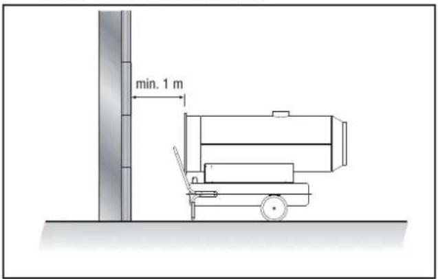
The minimum distance of the intake opening of the device to the wall must be at least 1m (see figure).
The minimum distance of the device to inflammable materials must be at least 2m
The intake and exhaust openings must not be covered.
There may be no walls or large objects near the device.
A sufficient number of fire-extinguishing systems must be available.
9. Description of device
The oil heating unit IDS 100 consists of the following components:
Oil heating unit
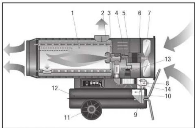
1 Combustion chamber
2 Burner 9 Heating oil circu
3 Nozzle 10 Support and handle
4 Pump 11 Wheel
5 Solenoid valve 12 Tank
6 Fan motor 13 Burner motor
7 Fan 14 Combustion air regulator
Control panel
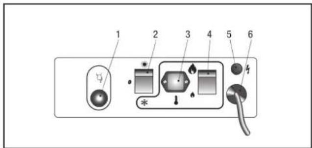
1 Reset button with indicator lamp
2 Selector switch
(ventilation/heating,thermostat operation)
3 Thermostat socket
4 Change-over switch, power stage (high-low)
5 Lamp
6 Power supply cable
10. Installation and commissioning
- Check that the scope of delivery of your oil heating unit is complete. If an accessory part is missing, please contact the Trotec customer service or the specialist dealer from whom you purchased the device.
- Check the oil heating unit and its connection parts for possible damages.
- Mount the support, the handle, the wheels and the outlet cone to the oil heating unit. Please refer to the supplied assembly instruction manual for further information. Please use the supplied assembly tools.
Make sure to comply with the requirements described in the chapter "Installation conditions". - Correctly connect the exhaust system of the device to a chimney or an external wall as shown in the chapter "Exhaust system".
- Fill the heating oil into the tank with the device switched off and cooled down.
- Inspect the device prior to commissioning and check it regularly for its proper condition during operation.
Make sure that the characteristics of the mains supply correspond to those indicated on the rating plate.
Each time before switching on the device, make sure that the fan can move freely before plugging the power plug into the mains socket. - Connect the power supply cable to a properly secured mains socket (230 V / 50 Hz / 10 A). On construction sites, a residual current circuit breaker must be connected upstream of the mains socket according to VDE 0100/0105.
The oil heating unit is now ready for operation. Use the device according to the functions described in chapter 12 "Functions and operation".
11. Exhaust system
Before planning the installation of the exhaust system, the local chimney sweep must be informed according to DIN 18160.

Risk of injury due to intoxication!
Improper installation of the exhaust system may cause health problems.
Have the installation carried out by a specialised craftsman!
- Make sure that an unobstructed and sufficient supply of combustion air is provided (e.g. by means of ventilation openings in doors, ceilings, windows, walls or an ambient air network) is provided.
- Have the exhaust gas values of the burner checked regularly.
Chimney duct
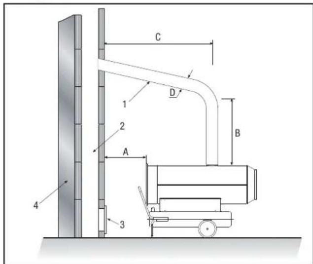
Wall duct
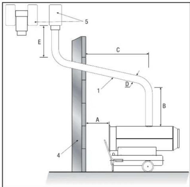
A min. 1 m
B min. 1 m
C as short as possible
D ≥0150 mm
E min.1 m
1 Wall duct with pipe elbow min. 5^
2 Chimney - min. internal dimensions 20x20 cm
3 Opening for cleaning with explosion
protection cap
4 External wall
5 Draft reinforcement, H-shaped
12. Functions and operation
The device may only be used by persons who have been trained in operating the device.
Switching on the oil heating unit
The oil heating unit features two operating modes:
- Manual mode
The device can operate in manual mode.
- Switch the device on by setting the selector switch to the position "燕窝" (ventilation).
The fan motor is started while the burner remains switched off.
2. Automatic mode
The oil heating unit can only operate in automatic mode if a control device (optional) is connected to it, e.g. a thermostat. The thermostat is to be connected to the thermostat socket.
- To be able to connect the thermostat, you must mount the provided thermostat socket. To this end, connect the power supply cable to the connection terminals 2 and 3 of the thermostat socket.
The removed conducting wire that connected the two connection terminals is to be reinstalled if the device is to be operated without thermostat.
- Switch the device on by setting the selector switch to the position " + (heating, thermostat operation).
The fan motor and burner motor are started and the combustion will start after a few seconds.
If the start-up cycle has been completed, the electronic control unit will confirm that the start-up of the device is complete by activating a red flashing light on the reset button.
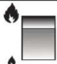
- Select the heating capacity of the device by setting the changeover switch to the low power stage (I S) or to the high power stage (I I S) (see figure).
IIS
IS
Switching off the oil heating unit
- Switch the device off by setting the selector switch to the position "0".
If you are using a thermostat, switch the device off via the settings of the control device (e.g. by setting the thermostat to a low temperature).
The flame is extinguished and the fan will continue running for approx. 90 seconds in order to cool down the burner.

Damage to the device due to overheating!
Do not switch off the device by pulling out the power cord. This may cause the device to overheat.
Switch the device off properly. Only disconnect the power plug if the fan motor has come to a complete standstill.
- Wait until the automatic aftercooling has been completed.
- Secure the device against being accidentally switched on again by pulling out the power cord.
Resuming operation after a failure
During the initial commissioning of the device or after the heating oil circuit has been completely emptied, the inflow of heating oil to the nozzle may be insufficient. This will cause the flame control system to be activated and the device will be blocked.
Wait for approx. 1 minute.
- Press and hold the reset button for at least 5 seconds.
- Switch on the device.
If the device is still not starting up:
Make sure that there is enough heating oil in the tank.
- Press the reset button.
In order to determine the cause of the fault:
see the chapters "Safety equipment" and "Troubleshooting
Safety equipment
The oil heating unit features an electronic flame and maximum temperature monitoring system that uses a photoelectric cell and a safety thermostat.
The electronic control unit controls the start-up, shutdown and safety shutdown times in the event of malfunctions. The control unit is equipped with a reset button whose colour (operation indicator) is depending on the operating mode:
- switched off if the device is in pause or standby mode and expecting the heating demand
- continuous green light for normal operation of the device
- continuous red light for safety shutdown of the device
- flashing orange light if the operation is interrupted due to considerable mains fluctuations (T < 175V or T > 265V) ; the operation is automatically resumed if the voltage has stabilised in the range of 190V to 250V
If the device has triggered the safety shutdown:
- Press and hold down the reset button for 3 seconds in order to resume operation.

Risk of injury due to deflagration!
Unburned heating oil may accumulate in the combustion chamber and can be ignited when the device is switched on the next time.
Do not restart the device two times in a row.
If the safety shutdown is still activated:
- Determine and remove the cause of the fault before commissioning the oil heating unit again (see chapter "Troubleshooting").
- Press and hold the reset button for at least 5 seconds.
The self-diagnostic programme will start. Once the programme has been completed, the reset button will light up in the colour (self-diagnostic indicator) depending on the cause of the fault:
- flashing orange light if an incorrect flame has been detected during start-up
- flashing red light if a missing flame has been detected during start-up
- flashing red/green light if a missing flame has been detected during operation
- continuous orange light if an internal error of the electronic control device has occurred
In order to determine the cause of the fault:
see chapter "Troubleshooting"
13. Transport
- Switch the device off as described in the chapter "Functions and operation".
Wait until the device has cooled down completely.
Before transporting or adjusting the device, check if the tank cap is tightly closed.

Risk of environmental pollution!
Heating oil may leak during transport or handling of the device. The filling plug of the tank cap does not guarantee tightness in order to allow air to be introduced and the tank to be emptied during operation.
Only transport or shift the device with the tank cap tightly closed.
14. Care and maintenance
In order to ensure a trouble-free operation of the device, the combustion chamber, the burner and the fan are to be cleaned regularly.
- Switch the device off as described in the chapter "Functions and operation".
- Wait until the device has cooled down completely.
Cleaning after every 50 operating hours
- Dismount the heating oil filter. Remove the filter insert and clean it using clean heating oil.
- Dismount the upper housing part and clean the inner part as well as the fan blades using a cleaning fleece and a brass brush if it is heavily soiled.
- Check the condition of all cables and high-voltage connections.
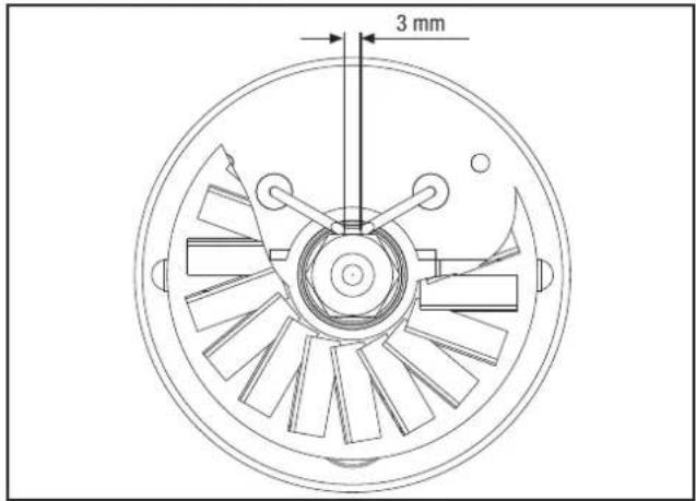
- Dismount the burner and clean its components using a brass brush.
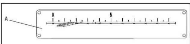
Clean the electrodes. Check the distance of the electrodes and adjust it if required (see figure).
- Have the combustion chamber cleaned by the customer service.
- Mount the components in the reverse order.
Cleaning the oil heating unit
- Wipe the exterior of the device using a wet cloth. The painted and plastic surfaces may not be scoured. Do not use any solvent-based cleaning agents.
15. Disposal
The heating oil must be drained from the tank of the oil heating unit and collected.
Oil heating unit
Electronic equipment may not be disposed of in the domestic waste, but must be correctly disposed of in accordance with the EUROPEAN PARLIAMENT directive 2002/96/EC of 27th January 2003 regarding used electrical and electronic equipment. Please dispose of this device according to the applicable legal regulations after its final decommissioning.
Heating oil
Fuels must be disposed of according to the local regulations.
Packaging
The packaging of the oil heating unit consists of cardboard/paper and plastic. The materials must be disposed of in the designated containers according to the local regulations or at a recycling depot.
16. Service and repair
Before contacting our customer service in order to solve an existing technical problem, please try removing the error by following the instructions described in the chapter "Troubleshooting".
If you have any further questions regarding the functioning and operation of the oil cleaning unit or if you wish to receive further information in the event of a claim or with regard to guarantee aspects, please do not hesitate to contact us at any time.
Please contact:
Trotec GmbH Co KG
Grebbener Straße 7
D-52525 Heinsberg
Tel.: 49 (0) 2452 / 962 - 400
Fax.: 49 (0) 2452 / 962 - 200
Email: info@trotec.de
www.trotec.de.
17. Troubleshooting

Danger to life due to improper repair!
Do no attempt to carry out modifications or repairs on the device. Any unauthorised modification may result in serious injuries or even death. Have repairs carried out by a certified specialist workshop.
| Problem | Reset button | Cause | Error correction | |
| Operation indicator | Self-diagnostic indicator | |||
| Fan does not start running and flame is not ignited | switched off | - | Control device is incorrectly set | - Check if the control equipment is correctly set (e.g. the temperature set at the thermostat must be higher than the room temperature). |
| Control device defective | - Have the control device replaced by the customer service. | |||
| Fan does not start running or switches off during start-up or operation | flashing orange light | - | no power supply | - Check the characteristics of the electrical system (230 V -1~ -50 Hz).- Check the function and position of the selector switch.- Check if the fuse is intact. |
| Voltage < 175 V | - Check the supply voltage. The device will automatically restart if the voltage exceeds 190 V. | |||
| Voltage > 265 V | - Check the supply voltage. The device will automatically restart if the voltage falls below 250 V. | |||
| Fan switches off during start-up or operation | continuous red light | flashing orange light | Flame is present prior to the ignition of the transformer | - Contact the customer service and have the device cleaned and heating oil residues removed from the combustion chamber. |
| Photoelectric cell defective | - Have the photoelectric cell replaced by the customer service. | |||
| flashing red light or flashing red/green light | Motor winding interrupted or blown | - Have the motor replaced by the customer service. | ||
| Motor bearing blocked | - Have the motor bearing replaced by the customer service. | |||
| Motor capacitor blown | - Have the motor capacitor replaced by the customer service. | |||
| no ignition | - Check the connections of the ignition cables to the electrodes and the transformer.- Check the position and the distance of the electrodes.- Check if the electrodes are clean.- Have the transformer replaced by the customer service. | |||
| Flame control system defective | - Have the flame control equipment replaced by the customer service. | |||
| Photoelectric cell defective | - Have the photoelectric cell cleaned or replaced by the customer service. | |||
| Burner is not or only insufficiently supplied with heating oil | Contact the customer service in order to:- have the integrity of the coupling between the pump and motor checked.- have the heating oil circuit checked for air that may have entered the circuit and to have the tightness of the lines and filter seal checked.- have the nozzle cleaned or replaced. | |||
| Solenoid valve defective | Contact the customer service in order to: - have the electrical connections checked. - have the safety thermostat LI checked. - have the solenoid valve cleaned or replaced. | |||
| continuous orange light | Internal error of the electronic control unit | Contact the customer service in order to: - have the control unit reset; try to start up the device at least twice. If the fault still occurs afterwards, replace the control unit. | ||
| Fan starts running and flame burns with smoke formation | continuous green light | - | insufficient supply of combustion air | - Remove all obstacles or blockages from the intake and/or exhaust openings. - Have the position of the air setting ring checked by the customer service. - Have the support disc of the burner cleaned by the customer service |
| Supply of combustion air too high | - Have the position of the air setting ring checked by the customer service. | |||
| used heating oil contaminated and/or containing water | - Replace used heating oil with clean heating oil. - Clean the heating oil filter. | |||
| air has entered the heating oil circuit | - Have the tightness of the lines and heating oil filter checked by the customer service | |||
| insufficient heating oil quantity at the burner | Contact the customer service in order to: - have the pump pressure value checked. - have the nozzle cleaned or replaced. | |||
| too much heating oil at the burner | Contact the customer service in order to: - have the pump pressure value checked. - have the nozzle replaced. | |||
| Device does not switch off | continuous green light | - | Solenoid valve seal defective | - Have the solenoid valve replaced by the customer service. |
18. Appendix
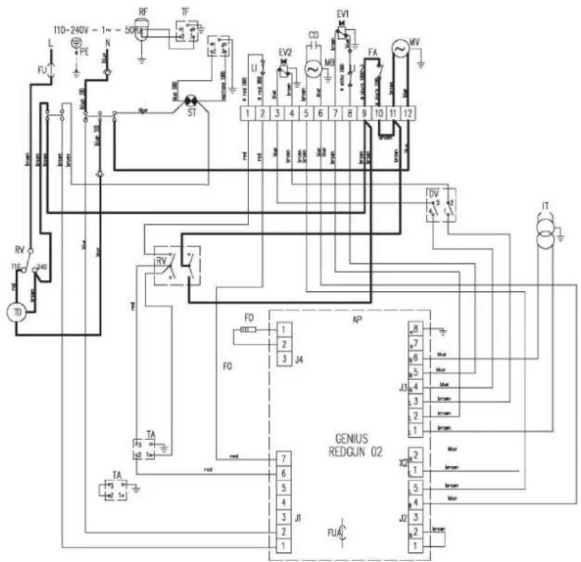
Circuit diagram
AP Control unit
F0 Photoelectric cell
TA Thermostat connection
C0 Capacitor
ST Indicator lamp
MV Fan motor
FU Fuse
MB Burner motor
LI 1 Safety thermostat
FUA Fuse
LI 2 Overheating protection, thermostat, LI
RV Selector switch
EV 1 Solenoid valve 1^ stage
FA Air regulator
EV 2 Solenoid valve II° stage
IT Ignition transformer
LF RFI filter
RF Heated filter (optional)
DV Change-over switch, power stage (high-low)
TF Plug for heated filter
TD Transformer
Setting of the air setting ring
| Type IDS 100 | |
| Parameter | Value |
| Setting of air setting ring | A=1.5 |
Table des matieres
LI 2 Overopphetingsvern termostat, L1
RV Valgbrtyer
EV 1 Magnetventil I° trinn
FA Luftregulator
EV2 Magnetventil II° trinn
IT enntransformator
LF Tenningsstoyfilter
RF Varmefilter (valgfritt)
DV Omkobler effekttrinn (hoy-lav)
TF Plugg for varmefilter
TD Transformer