
One+ EMS190DCL - Electric saw RYOBI - Free user manual and instructions
Find the device manual for free One+ EMS190DCL RYOBI in PDF.
| Product type | Cordless sliding compound miter saw |
| Brand | RYOBI |
| Model | One+ EMS190DCL |
| Power supply | 18 V lithium-ion battery (One+ system) |
| Blade diameter | 190 mm |
| Weight | Approximately 18 kg |
| Dimensions (L × W × H) | Approximately 600 × 400 × 400 mm |
| Cutting capacities | Miter: 45° left to 45° right; Bevel: 0° to 45° |
| Compatible materials | Solid wood, chipboard, panels, plastics |
| Key features | Adjustable main guide, integrated clamp, miter and bevel stops, rotating table |
| Safety | Self-closing lower blade guard, arbor lock, safety switch, blade brake, anti-tip safety |
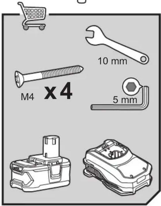
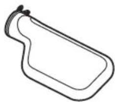
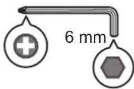
| Included accessories | Dust bag, clamp, hex key, blade flanges, main guide |
| Maintenance and cleaning | Clean regularly with a brush or vacuum; do not use compressed air |
| Repairability | Repairs by authorized service center only; use original Ryobi parts |
| Warranty | 24 months standard, 12-month extension possible via online registration |
| Operating temperature | From 0 °C to 40 °C |
Frequently Asked Questions - One+ EMS190DCL RYOBI
User questions about One+ EMS190DCL RYOBI
0 question about this device. Answer the ones you know or ask your own.
Ask a new question about this device
Download the instructions for your Electric saw in PDF format for free! Find your manual One+ EMS190DCL - RYOBI and take your electronic device back in hand. On this page are published all the documents necessary for the use of your device. One+ EMS190DCL by RYOBI.
USER MANUAL One+ EMS190DCL RYOBI
natural_image
Ryobil cutting machine with blade and workpiece, no visible text or symbols on the device itself


| Important! | It is essential that you read the instructions in this manual before assembling, maintaining and operating the product. |
| Attention! | Il est essentiel que vous lisiez les instructions contenues dans ce manuel avant d'assembler, d'entretenir et d'utiliser le produit. |
| Achtung! | Es ist wichtig, dass Sie vor Zusammenbau, Wartung und Benutzung des Produktes die Anweisungen in dieser Anleitung lesen. |
| ¡Atención! | Resulta fundamental que lea este manual de instrucciones antes de realizar el montaje, el mantenimiento y de utilizar este producto |
| Attenzione! | E' importante leggere le istruzioni contenute nel presente manuale prima di montare il prodotto, svolgere le operazioni di manutenzione sullo stesso e metterlo in funzione. |
| Let op! | Het is van essentieel belang dat u de instructies in deze gebruiksaanwijzing leest voor u het product monteert, onderhoudt en gebruikt. |
| Atenção! | É fundamental que leia as instruções deste manual antes da montagem, manutenção e operação do aparelho. |
| OBS! | Det er vigtigt, at man læser instrukserne i denne brugsanvisning, inden man samler, vedligeholder og betjener produktet. |
| Observera! | Det är viktigt att du läser instruktionerna i manualen före montering, användning och underhåll av produkten. |
| Huomio! | On tärkeää, että luet tämän käsikirjan ohjeet ennen tuotteen kokoamista, huoltoa ja käyttöä. |
| Advarsel! | Det er viktig at du leser instruksjonene i denne manualen før sammensetning, vedlikehold og bruk av produktet |
| Внимание! | Необходимо прочитать инструкции в данном руководстве перед сборкой, обслуживанием и эксплуатацией этого изделия. |
| Uwaga! | Koniecznie należy przeczytać instrukcje zawarte w tym podręczniku przed montażem, obsługą konserwacją produktu. |
| Dûležité upozornění! | Neinstalujte, neprovádějte údržbu ani nepoužívejte tento výrobek dríve, než si přečtete pokyny uvedené v tomto návodu. |
| Figyelem! | Fontos, hogy a termék összeszerelése, karbantartása és használata előtt elolvassa a kezikó található utasításokat. |
| Atenție! | Este esențial să citiți instrucțiunile din acest manual înainte de asamblare, efectuarea între operarea produsului. |
| Uzmanību! | Ir svarīgi izlasīt šīs rokasgrāmatas instrukcijas pirms uzstādīšanas, apkopes un preces darbināšanas. |
| Dèmesio! | Prieš surenkant, prižiūrint ir naudojant gaminį, būtina perskaityti šiame vadove pateiktus nurodymus. |
| Tähtis! | Enne masina kokkupanekut, hooldamist ja kasutama hakkamist tuleb käesolevas juhendis esitatud juhised kindlasti läbi lugeda. |
| Upozorenje! | Vrlo je važno da ste prije sklapanja, održavanja i rada s ovim proizvodom pročitali upute u ovom priručniku. |
| Pomembno! | Pomembno je da pred montažo vzdrževanjem in uporabo tega izdelka preberete navodila v tem priročniku. |
| Upzornenie! | Je dôležité, aby ste si pred montážou, údržbou a obsluhou produktu prečitali pokyny v tomto návode. |
| Bажно! | Изключително важно е да прочетете инструкциите в настоящото ръководство, преди да преминете към сглобяване, поддръжка или работа с продукта. |
| Важливо! | Дуже важливо, щоб ви прочитали інструкції в цьому керівництві перед складанням, обслуговуванням та експлуатацією цієї машини. |
| Dikkat! | Ürünün montajini, bakımını yapmadan ve ürünü_classtirmadan önce bu kılavuzda yer alan okumanız önemlidir. |
| Простохн! | Еівαι полú σημαντικό να διαβάσετε τις οδηγίες στο παρόν εγχειρίδιο πριν συναρμολογήσετε, συντηρήσετε ή λειτουργήσετε το προϊόν. |
Subject to technical modification | Sous réserve de modifications techniques | Technische Änderungen vorbehalten | Bajo reserva de modificaciones técnicas | Con riserva di eventuali modifiche tecniche | Technische wijzigingen voorbehouden | Com reserva de modificações técnicas | Med forbehold for tekniske ændringer | Med förbehåll för tekniska ändringar | Tekniset muutokset varataan | Med forbehold om tekniske endringer | могут быть внесены технические изменения | Z zastrzeżeniem modyfikacji technicznych | Změny technických údajů vyhrazeny | A műszaki módosítás jogát fenntartjuk | Sub rezerva modificațiilor tehnice | Paturam tiesības mainīt tehniskos raksturlielumus | Pasiliekant teisę daryti techninius pakeitimus | Tehnilised muudatused võimalikud | Podloæno tehniëkim promjenama | Tehnične spremembe dopuščene | Právo na technické zmeny je vyhradenė | Подлежи на технически модификации | Є об'єктом для технічних змін | Teknik değişiklik hakki saklıdır | Упó тнүv επιφύλαξη τεχνικών τροποποιήσεων

Safety, performance, and dependability have been given top priority in the design of your mitre saw.
INTENDED USE
The mitre saw is intended for sawing solid and bonded wood, materials similar to wood, with or without glued veneer and plastics.
The mitre saw is intended to be used only by adult operators who have read the instruction manual and understand the risks and hazards.
The mitre saw is designed to be fixed at solid bench top. If the base is not securely whole machine may move during cutting operations, which increases the possibility of serious personal injury.
The mitre saw is designed to make bevel and mitre cuts. The capacities for the various cuts are provided in the product specifications in this manual.
The mitre saw is to be used in dry conditions, with excellent ambient lighting and adequate ventilation.
The mitre saw is intended for consumer use and should only be used as described above and is not intended for any other purpose.
GENERAL POWER TOOL SAFETY WARNINGS
WARNING
Read all safety warnings, instructions, illustrations and specifications provided with this power tool. Failure to follow all instructions listed below may result in electric shock, fire and/or serious injury.
Save all warnings and instructions for future reference. The term "power tool" in the warnings refers to your mains-operated (corded) power tool or battery-operated (cordless) power tool.
WORK AREA SAFETY
- Keep work area clean and well lit. Cluttered or dark areas invite accidents.
- Do not operate power tools in explosive atmospheres, such as in the presence of flammable liquids, gases or dust. Power tools create sparks which may ignite the dust or fumes.
- Keep children and bystanders away while operating a power tool. Distractions can cause you to lose control.
ELECTRICAL SAFETY
■ Power tool plugs must match the outlet. Never modify the plug in any way. Do not use any adapter plugs with earthed (grounded) power tools. Unmodified plugs and matching outlets will reduce risk of electric shock.
- Avoid body contact with earthed or grounded surfaces, such as pipes, radiators, ranges and refrigerators. There is an increased risk of electric shock if your body is earthed or grounded.
- Do not expose power tools to rain or wet conditions.
Water entering a power tool will increase the risk of electric shock.
- Do not abuse the cord. Never use the cord for carrying, pulling or unplugging the power tool. Keep cord away from heat, oil, sharp edges or moving parts. Damaged or entangled cords increase the risk of electric shock.
- When operating a power tool outdoors, use an extension cord suitable for outdoor use. Use of a cord suitable for outdoor use reduces the risk of electric shock.
If operating a power tool in a damp location is unavoidable, use a residual current device (RCD) the base to a protected supply. Use of an RCD reduces the risk of fixed the electric shock.
PERSONAL SAFETY
- Stay alert, watch what you are doing and use common sense when operating a power tool. Do not use a power tool while you are tired or under the influence of drugs, alcohol or medication. A moment of inattention while operating power tools may result in serious personal injury.
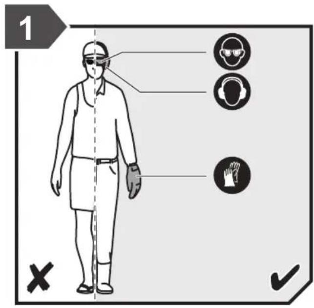
■ Use personal protective equipment. Always wear eye protection. Protective equipment such as a dust mask, non-skid safety shoes, hard hat, or hearing protection used for appropriate conditions will reduce personal injuries.
■ Prevent unintentional starting. Ensure the switch is in the off -position before connecting to power source and/or battery pack, picking up or carrying the tool. Carrying power tools with your finger on the switch or energising power tools that have the switch on invites accidents.
■ Remove any adjusting key or wrench before turning the power tool on. A wrench or a key left attached to a rotating part of the power tool may result in personal injury. - Do not overreach. Keep proper footing and balance at all times. This enables better control of the power tool in unexpected situations.
■ Dress properly. Do not wear loose clothing or jewellery. Keep your hair and clothing away from moving parts. Loose clothes, jewellery or long hair can be caught in moving parts.
If devices are provided for the connection of dust extraction and collection facilities, ensure these are connected and properly used. Use of dust collection can reduce dust-related hazards. - Do not let familiarity gained from frequent use of tools allow you to become complacent and ignore tool safety principles. A careless action can cause severe injury within a fraction of a second.
POWER TOOL USE AND CARE
- Do not force the power tool. Use the correct power tool for your application. The correct power tool will do the job better and safer at the rate for which it was designed.
- Do not use the power tool if the switch does not turn it on and off. Any power tool that cannot be controlled with the switch is dangerous and must be repaired.
■ Disconnect the plug from the power source and/or remove the battery pack, if detachable, from
the power tool before making any adjustments, changing accessories, or storing power tools. Such preventive safety measures reduce the risk of starting the power tool accidentally.
■ Store idle power tools out of the reach of children and do not allow persons unfamiliar with the power tool or these instructions to operate the power tool. Power tools are dangerous in the hands of untrained users.
- Maintain power tools and accessories. Check for misalignment or binding of moving parts, breakage of parts and any other condition that may affect the power tool's operation. If damaged, have the power tool repaired before use. Many accidents are caused by poorly maintained power tools.
- Keep cutting tools sharp and clean. Properly maintained cutting tools with sharp cutting edges are less likely to bind and are easier to control.
■ Use the power tool, accessories and tool bits etc. in accordance with these instructions, taking into account the working conditions and the work to be performed. Use of the power tool for operations different from those intended could result in a hazardous situation.
- Keep handles and grasping surfaces dry, clean and free from oil and grease. Slippery handles and grasping surfaces do not allow for safe handling and control of the tool in unexpected situations.
BATTERY TOOL USE AND CARE
■ Recharge only with the charger specified by the manufacturer. A charger that is suitable for one type of battery pack may create a risk of fire when used with another battery pack.
■ Use power tools only with specifically designated battery packs. Use of any other battery packs may create a risk of injury and fire.
- When battery pack is not in use, keep it away from other metal objects, like paper clips, coins, keys, nails, screws or other small metal objects, that can make a connection from one terminal to another. Shorting the battery terminals together may cause burns or a fire.
■ Under abusive conditions, liquid may be ejected from the battery; avoid contact. If contact accidentally occurs, flush with water. If liquid contacts eyes, additionally seek medical help. Liquid ejected from the battery may cause irritation or burns.
- Do not use a battery pack or tool that is damaged or modified. Damaged or modified batteries may exhibit unpredictable behaviour resulting in fire, explosion or risk of injury.
- Do not expose a battery pack or tool to fire or excessive temperature. Exposure to fire or temperature above 130°C may cause explosion.
■ Follow all charging instructions and do not charge the battery pack or tool outside the temperature range specified in the instructions. Charging improperly or at temperatures outside the specified range may damage the battery and increase the risk
of fire.
SERVICE
- Have your power tool serviced by a qualified repair person using only identical replacement parts. This will ensure that the safety of the power tool is maintained.
■ Never service damaged battery packs. Service of battery packs should only be performed by the manufacturer or authorized service providers.
SAFETY INSTRUCTIONS FOR MITRE SAWS
- Mitre saws are intended to cut wood or wood-like products, they cannot be used with abrasive cut-off wheels for cutting ferrous material such as bars, rods, studs, etc. Abrasive dust causes moving parts such as the lower guard to jam. Sparks from abrasive cutting will burn the lower guard, the kerf insert and other plastic parts.
- Use clamps to support the workpiece whenever possible. If supporting the workpiece by hand, you must always keep your hand at least 100 mm from either side of the saw blade. Do not use this saw to cut pieces that are too small to be securely clamped or held by hand. If your hand is placed too close to the saw blade, there is an increased risk of injury from blade contact.
The workpiece must be stationary and clamped or held against both the fence and the table. Do not feed the workpiece into the blade or cut "freehand" in any way. Unrestrained or moving workpieces could be thrown at high speeds, causing injury. - Push the saw through the workpiece. Do not pull the saw through the workpiece. To make a cut, raise the saw head and pull it out over the workpiece without cutting, start the motor, press the saw head down and push the saw through the workpiece. Cutting on the pull stroke is likely to cause the saw blade to climb on top of the workpiece and violently throw the blade assembly towards the operator.
- Never cross your hand over the intended line of cutting either in front or behind the saw blade. Supporting the workpiece “cross handed” i.e. holding the workpiece to the right of the saw blade with your left hand or vice versa is very dangerous.
- Do not reach behind the fence with either hand closer than 100 mm from either side of the saw blade, to remove wood scraps, or for any other reason while the blade is spinning. The proximity of the spinning saw blade to your hand may not be obvious and you may be seriously injured.
- Inspect your workpiece before cutting. If the workpiece is bowed or warped, clamp it with the outside bowed face toward the fence. Always make certain that there is no gap between the workpiece, fence and table along the line of the cut. Bent or warped workpieces can twist or shift and may cause binding on the spinning saw blade while cutting. There should be no nails or foreign objects in the workpiece.
- Do not use the saw until the table is clear of all tools, wood scraps, etc., except for the workpiece.
Small debris or loose pieces of wood or other objects that contact the revolving blade can be thrown with high speed.
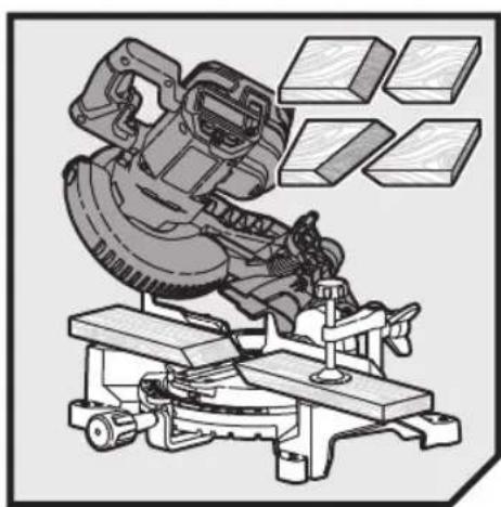
- Cut only one workpiece at a time. Stacked multiple workpieces cannot be adequately clamped or braced and may bind on the blade or shift during cutting.
■ Ensure the mitre saw is mounted or placed on a level, firm work surface before use. A level and firm work surface reduces the risk of the mitre saw becoming unstable.
Plan your work. Every time you change the bevel or mitre angle setting, make sure the adjustable fence is set correctly to support the workpiece and will not interfere with the blade or the guarding system. Without turning the tool "ON" and with no workpiece on the table, move the saw blade through a complete simulated cut to assure there will be no interference or danger of cutting the fence.
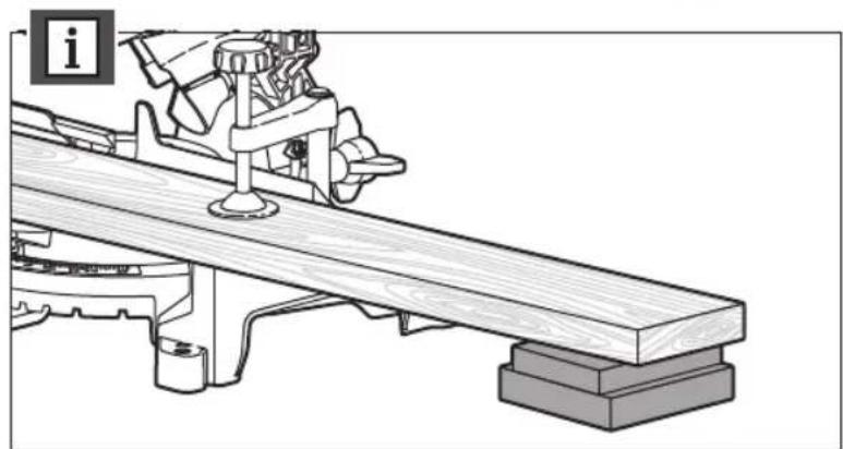
■ Provide adequate support such as table extensions, saw horses, etc. for a workpiece that is wider or longer than the table top. Workpieces longer or wider than the mitre saw table can tip if not securely supported. If the cut-off piece or workpiece tips, it can lift the lower guard or be thrown by the spinning blade. - Do not use another person as a substitute for a table extension or as additional support. Unstable support for the workpiece can cause the blade to bind or the workpiece to shift during the cutting operation pulling you and the helper into the spinning blade.
■ The cut-off piece must not be jammed or pressed by any means against the spinning saw blade. If confined, i.e. using length stops, the cut-off piece could get wedged against the blade and thrown violently.
■ Always use a clamp or a fixture designed to properly support round material such as rods or tubing. Rods have a tendency to roll while being cut, causing the blade to "bite" and pull the work with your hand into the blade. - Let the blade reach full speed before contacting the workpiece. This will reduce the risk of the workpiece being thrown.
If the workpiece or blade becomes jammed, turn the mitre saw off. Wait for all moving parts to stop and disconnect the plug from the power source and/or remove the battery pack. Then work to free the jammed material. Continued sawing with a jammed workpiece could cause loss of control or damage to the mitre saw.
■ After finishing the cut, release the switch, hold the saw head down and wait for the blade to stop before removing the cut-off piece. Reaching with your hand near the coasting blade is dangerous. - Hold the handle firmly when making an incomplete cut or when releasing the switch before the saw head is completely in the down position. The braking action of the saw may cause the saw head to be suddenly pulled downward, causing a risk of injury.
SAFETY INSTRUCTIONS FOR WOOD CUTTING BLADE
■ Please read the manual and instructions carefully before using the saw blade and the machine.
■ The product must be in good condition, the spindle without deformation and vibration.
- Do not use the product without the guards in position. Keep guards in good working order and properly maintained.
■ Ensure the operator is adequately trained in safety precautions, adjustment and operation of the product.
■ Always wear goggles and ear protection when using the product. It is recommended to wear gloves, sturdy non slipping shoes and apron.
■ Before using any accessory, consult the instruction manual. The improper use of an accessory can cause damage and increase the potential for injury.
■ Use only blades specified in this manual, complying with EN 847-1.
- Observe the maximum speed marked on the saw blade. Ensure the speed marked on the saw blade is at least equal to the speed marked on the saw.
■ Always use blades with correct size and shape of arbour holes. Blades that do not match the mounting hardware of the saw will run eccentrically, causing loss of control.
- Do not use blades of larger or smaller diameter than recommended. Do not use any spacers to make the blade fit onto the spindle.
- Check the tips of the saw blade for damage or abnormal appearance before each use. Tips that are damaged or loose can become flying objects in use and increase the chance of personal injury.
- Do not use cracked or distorted saw blades. Do not use saw blades that are damaged or deformed.
- Scrap the saw blade if damaged, deformed, distorted or cracked, repairing is not permitted.
■ Do not use HSS blades.
■ Ensure the saw blade is mounted correctly, tighten the arbor nut securely before use (tightening torque approx. 8-10 Nm).
■ Fastening screw and nuts shall be tightened using the appropriate spanner, etc.
■ Extension of the spanner or tightening using hammer blows is not permitted.
■ Make sure the blade and flanges are clean and the recessed sides of the collar are against the blade.
■ Make sure the blade rotates in the correct direction.
■ Before work, make a dummy cut without the motor turned on so the position of the blade, operation of the guards with respect to other machine parts and workpiece may be checked.
■ Never leave the product unattended.
■ Do not apply lubricants on the blade when it is running.
■ Never perform any cleaning or maintenance work when the machine is still running and the head is not in the rest position.
■ Never attempt to stop a machine in motion rapidly
by jamming a tool or other means against the blade, serious accidents can be caused unintentionally in this way.
■ Disconnect the product from the mains supply or remove battery pack before changing blades or carrying out maintenance.
■ Pay attention to blade packing and unpacking, it is easy to be injured by the sharp blade tips.
■ Use a blade holder or wear gloves when handling a saw blade.
- Keep and store the blade in original packaging or other suitable packaging, keep in dry conditions and away from chemicals which may damage the blade.
ADDITIONAL SAFETY WARNINGS
■ Always clamp the workpiece safely and securely.
■ Ensure that the product is always stable and secure (e.g., fixed to a bench).
■ Always wear ear protectors. Exposure to noise can cause hearing loss.
■ Always wear safety goggles when using the product. It is recommended to wear gloves for handling blades and rough material, plus sturdy non slip shoes to protect the feet from workpieces which may fall from the cutting area.
■ Disconnect the product from the mains supply or remove battery pack before carrying out any maintenance or cleaning the product.
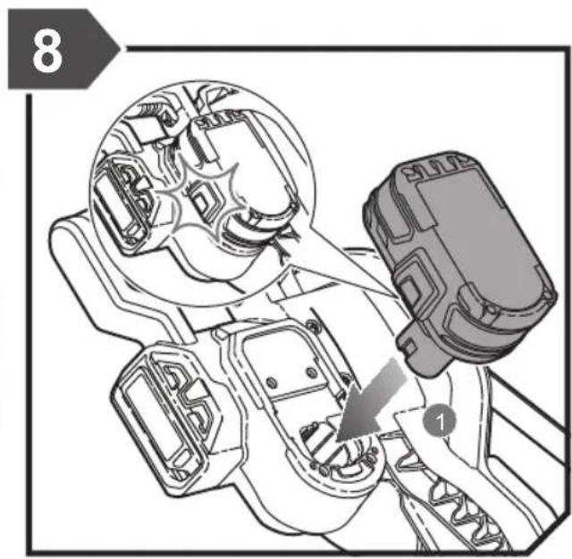
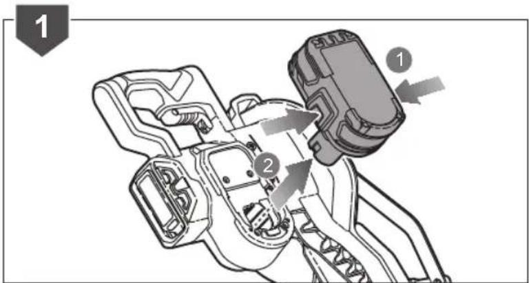
■ Only install the battery pack when the product is switched off.
■ Never reach into the area near the blade unless the blade has completely stopped.
■ Before use, thoroughly check the product and battery pack for any damage or material fatigue. Repairs to the whole product should only be carried out by an authorised service centre.
■ Always use the guards on the product. Do not use the product if the guards are not in place and working correctly.
■ The lower blade guard should only open when the blade is lowered to the workpiece and must always be able to move freely and close automatically.
■ Always fix and use extension bars for workpiece support during operation.
■ Never alter of modify the product or its function. Your safety may be compromised.
- Do not use saw blades which are cracked, damaged or deformed.
■ Do not use saw blades made of high-speed steel.
■ Only use blades that are sharp. Replace dull blades.
■ Always use blades with correct size and shape of arbour holes. Blades that do not match the mounting hardware of the saw will run eccentrically, causing loss of control.
■ Use only woodworking blades specified in this manual, which comply with EN 847-1.
- Do not use any flanges, washers and nuts to secure the saw blade other than those supplied or indicated in the instruction manual.
It is necessary to select a saw blade which is suitable for the material being cut. Never use the product to cut materials other than those specified in the intended use section in this manual.
■ It is important to avoid overheating the blade and melting the plastic when cutting.
It is essential to adhere to the maximum speed specified on the saw blade, only use saw blade that are marked with a speed equal or higher than the speed marked on the tool.
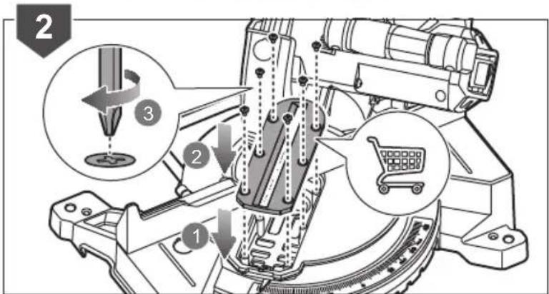
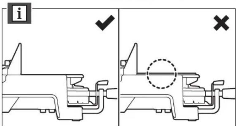
- Replace the table insert when worn or damaged.
■ Before work, make a dummy cut without the motor turned on so the position of the blade, operation of the guards with respect to other machine parts, and workpiece may be checked.
■ When performing mitre, bevel or compound mitre cuts, adjust the sliding fence or sub-fence to ensure the correct clearance from the blade.
■ The handle lock must always be engaged when transporting the product.
- Keep the floor area free of loose materials, such as chips and cut-offs.
■ Refrain from removing any cut-offs or other parts of the workpiece from the cutting area whilst the product is running and the saw head is not in the rest position.
■ Long workpieces must be adequately supported. The working area of the saw includes the whole extent of the workpiece. The operator should secure this area from accidental contact from other persons or objects which may move the workpiece during operation.
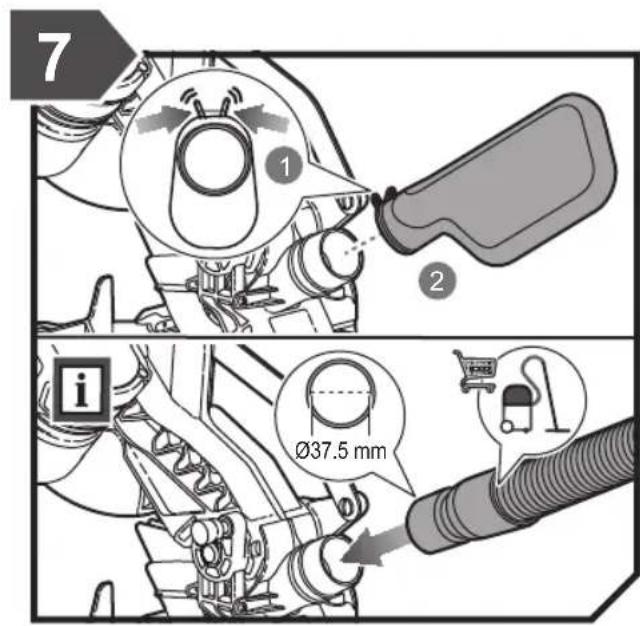
The dust produced when using the product may be harmful to health. Use a dust suction system and wear a suitable dust protection mask. Remove deposited dust thoroughly with a vacuum cleaner.
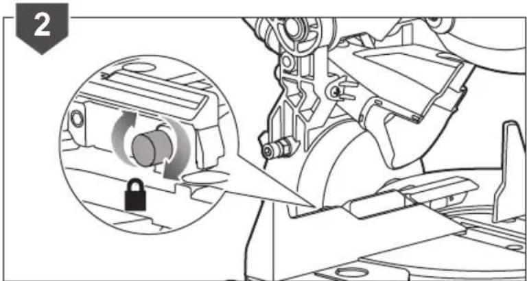
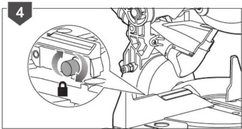
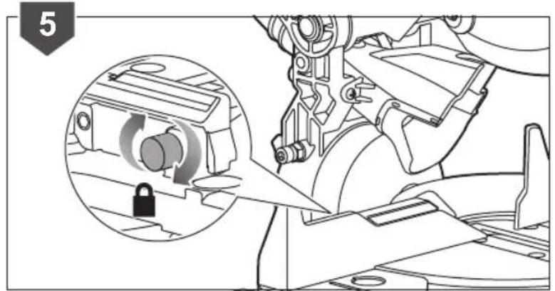
It may be necessary to adjust the sliding fence to ensure proper clearance prior to making a bevel or compound cut. Make sure the sliding fence lock screw is tightened securely after the adjustment.
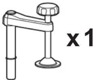
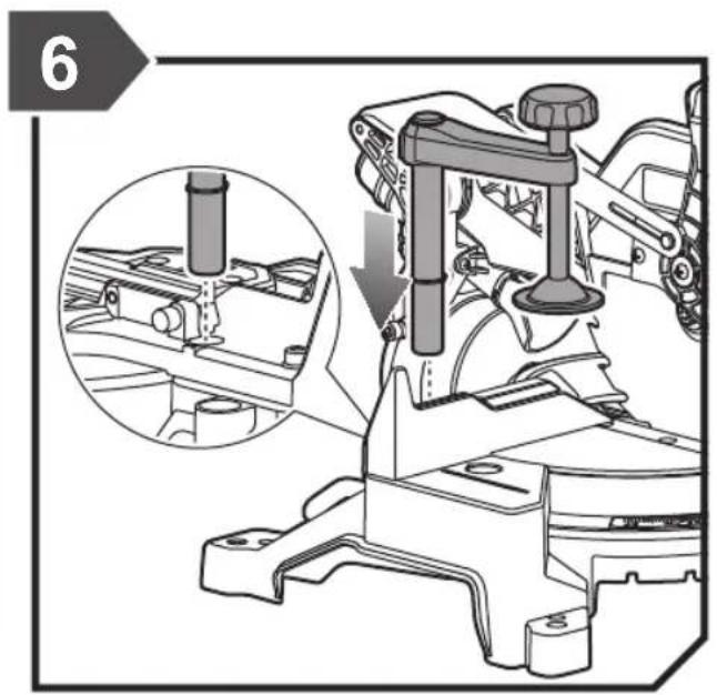
The clamp can be installed and used on either side of the blade. In some operation, the clamp may interfere with the blade guard assembly. Always make sure there is no interference with the blade guard prior to beginning any cutting operation to reduce the risk of serious personal injury.
■ Ambient temperature range for tool during operation is between 0 °C and 40°C.
■ Ambient temperature range for tool storage is between 0 °C and 40° C.
■ The recommended ambient temperature range for the charging system during charging is between 10 °C and 38°C.
TRANSPORTING LITHIUM BATTERIES
Transport the battery in accordance with local and national provisions and regulations.
Follow all special requirements on packaging and labelling when transporting batteries by a third party. Ensure that no batteries can come in contact with other batteries or conductive materials while in transport by protecting exposed connectors with insulating, non-conductive caps
4 | English
or tape. Do not transport batteries that are cracked or leaking. Check with the forwarding company for further advice.
ADDITIONAL BATTERY SAFETY WARNINGS
WARNING
To reduce the risk of fire, personal injury, and product damage due to a short circuit, never immerse your tool, battery pack or charger in fluid or allow a fluid to flow inside them. Corrosive or conductive flu as seawater, certain industrial chemicals, and bleach or bleach-containing products, etc., can cause a short circuit.
■ Ambient temperature range for battery during use is between 0 °C and 40°C.
■ Ambient temperature range for battery storage is between 0 °C and 20° C.
RESIDUAL RISKS
Even when the product is used as prescribed, it is still impossible to completely eliminate certain residual risk factors. The following hazards may arise and the operator should pay special attention to avoid the following:
■ Risk of contact with uncovered parts of the rotating saw blade
■ Kick-back of workpieces or parts of workpieces due to improper adjustment or handling
■ Catapulting of faulty carbide tips from the saw blade
■ Damage to the respiratory system
NOTE: Wear respiratory protection masks containing filters appropriate to the materials being worked. Ensure adequate workplace ventilation. Do not eat, drink or smoke in the work area.
■ Damage to hearing if effective hearing protection is not worn.
WARNING
Dust from certain paints, coatings and materials may cause irritation or allergic reactions to the respiratory system. Dust from wood such as oak, beech, MDF and others are carcinogenic. Material containing asbestos should only ever be worked or processed by specialist operators.
WARNING
Injuries may be caused, or aggravated, by prolonged use of a tool. When using any tool for prolonged periods, ensure you take regular breaks.
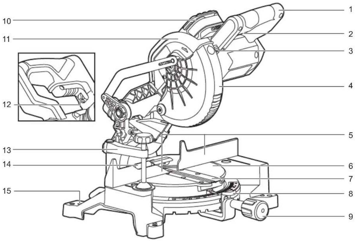
KNOW YOUR PRODUCT
See page 217.
- Handle, insulated gripping surface
- Power switch
-
Spindle lock button
-
Lower guard
- Main fence
- Turntable
- Table insert
- Mitre detent release lever
- Mitre lock knob
- Battery pack
- Upper guard
- Switch lock-off lever
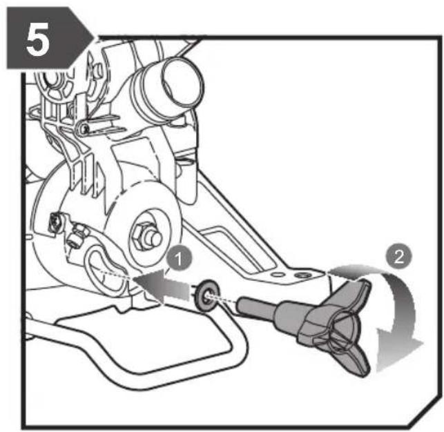
- Clamp
- Sliding fence
uids,15. Mounting hole - Screws for locking main fence
- Hex key
- Screws for adjusting 45° bevel angle limit stop
- Bevel angle lock knob
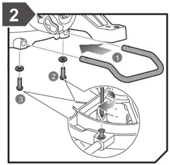
- Anti-tip bar
- Dust bag
- Screws for adjusting 0° bevel angle limit stop
- Screw for locking the sliding fence
- Outer flange
- Saw blade
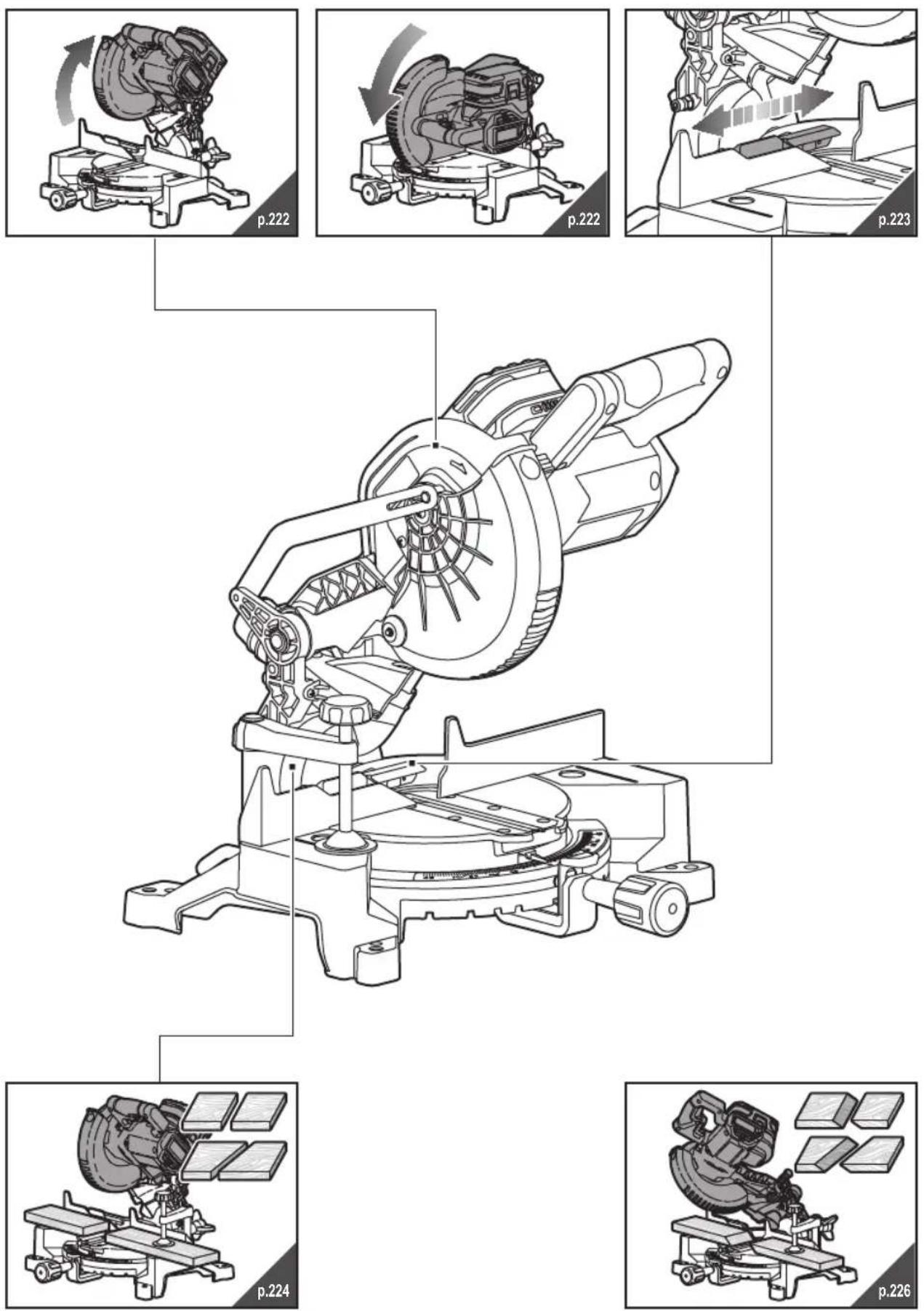
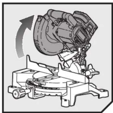
OPERATION
The product features a moving saw blade that can be set at various angles by the operator when cutting a workpiece which is securely fixed to the base of the product. It must be operated by only one person to prevent unintentional contact with the moving saw blade.
The principles for safe operation of the product are as follows:
- Maintain saw, blades and work area in good condition.
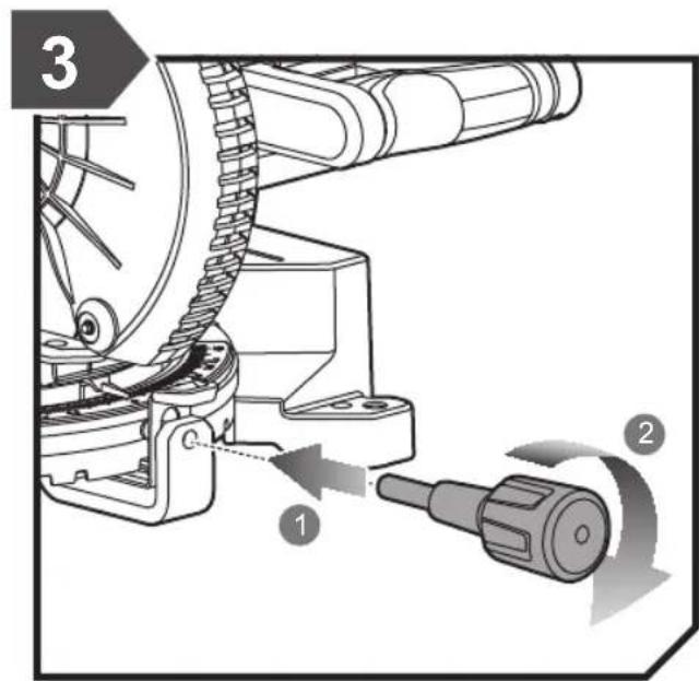
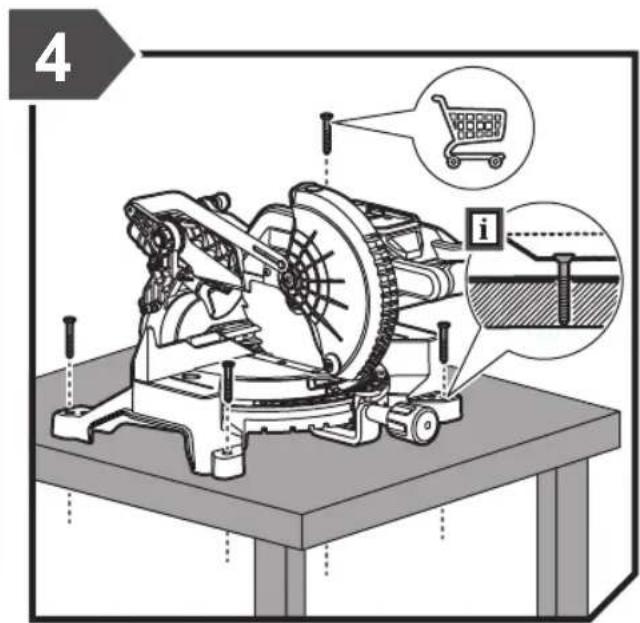
- Secure the mitre saw base to a sturdy work bench. The product may move and tip if it is not adequately secured.
■ Set up and lock the cutting angles and depth before making the cut. - Secure the workpiece to the mitre saw base. Use the clamp provided and, where necessary, use additional clamps or holding mechanisms to prevent unintentional movement of the workpiece while cutting.
- Check that the operation of the blade guards are not restricted by the position of the workpiece.
- Ensure that the fence and other parts of the product will not be cut as the blade lowers to the cutting position.
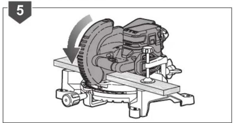
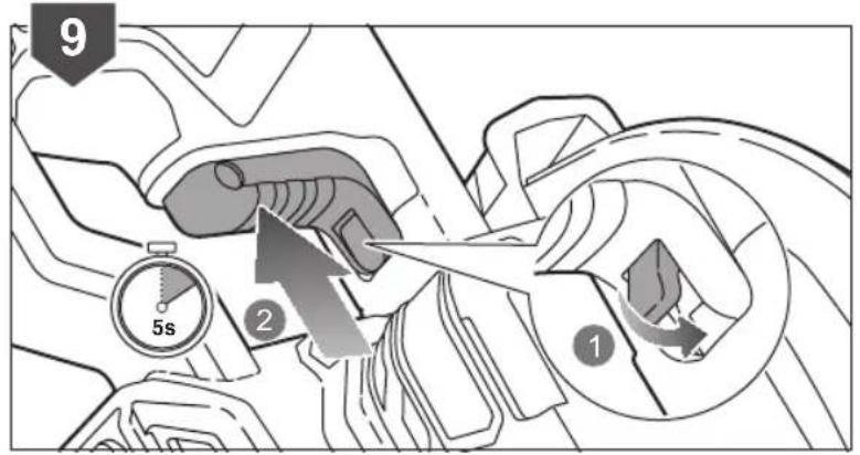
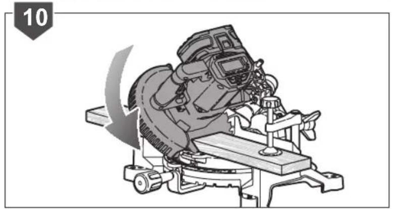
■ Start the motor and allow the blade to reach full speed before slowly lowering it to cut the workpiece.
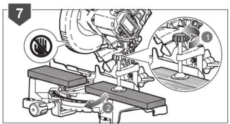
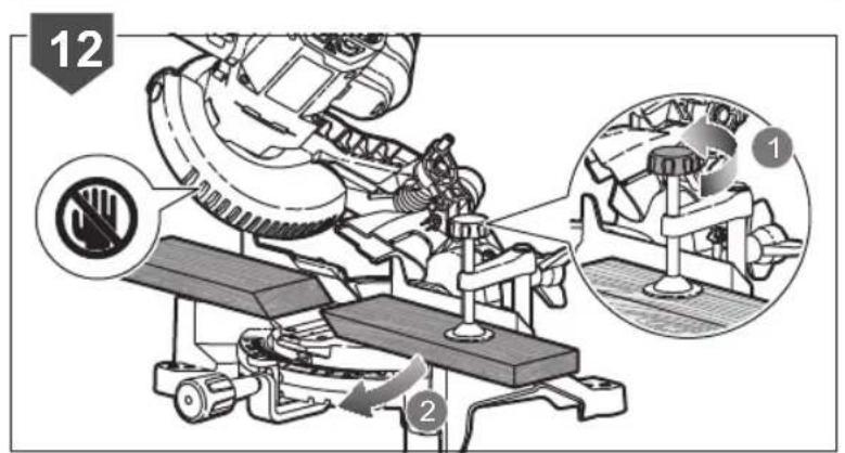
- Allow the blade assembly to rise to its upper position where the blade guards are fully closed. Switch off the motor and allow the blade to come to a complete stop before removing the workpiece or off-cuts, or before reaching into the area of the blade.
Before first use, ensure that the angle of the bevel or mitre set on the product matches the angle to be produced on the workpiece. Check this on a discarded piece of wood by using a carpenter's set or mitre square.
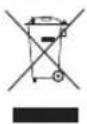
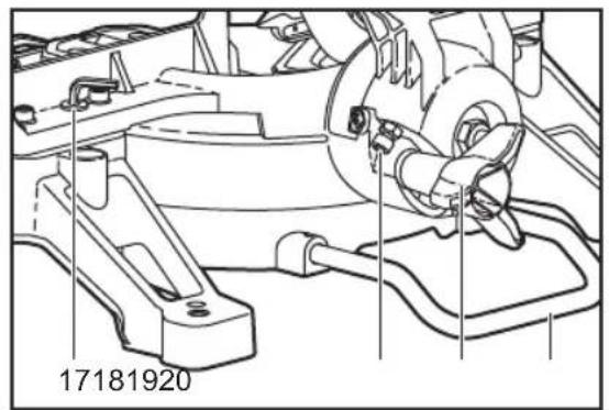
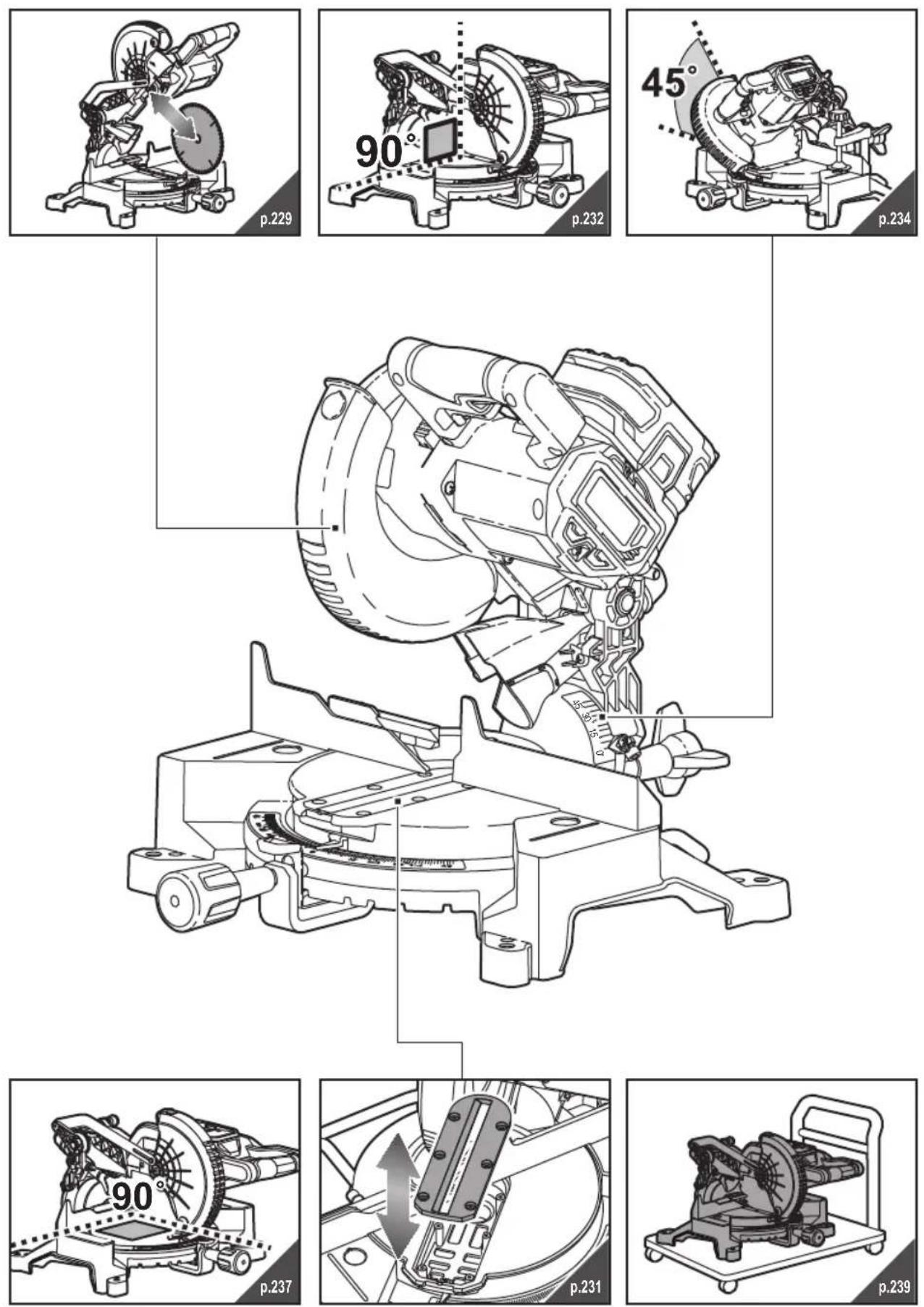
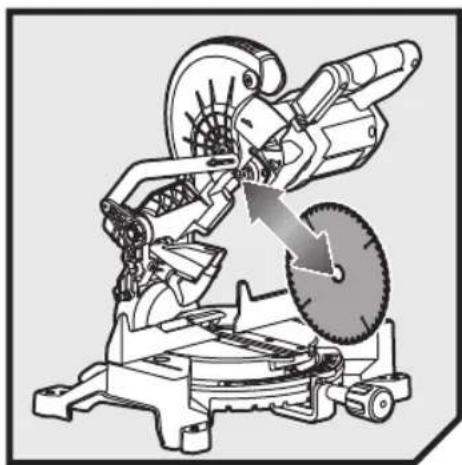
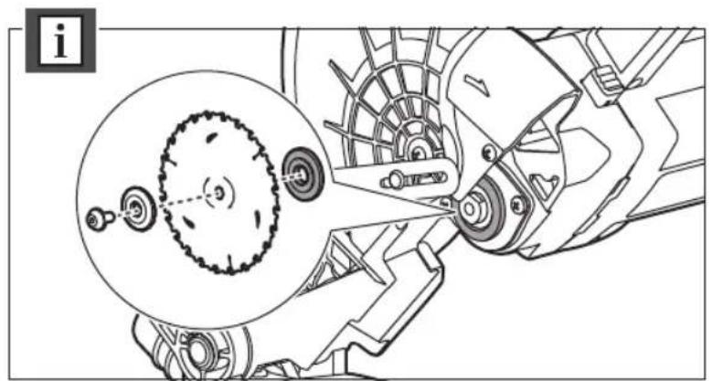
Remove saw blade:
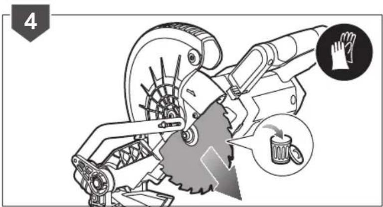
- Wear gloves when handling saw blade.
-
Turn off the power and remove the battery pack.
-
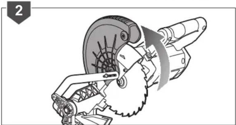
Swing back the self-closing guard and hold it.
- Press spindle lock button and unscrew the blade bolt with provided hex key at the same time. Remove the outer flange.
- Remove the saw blade.
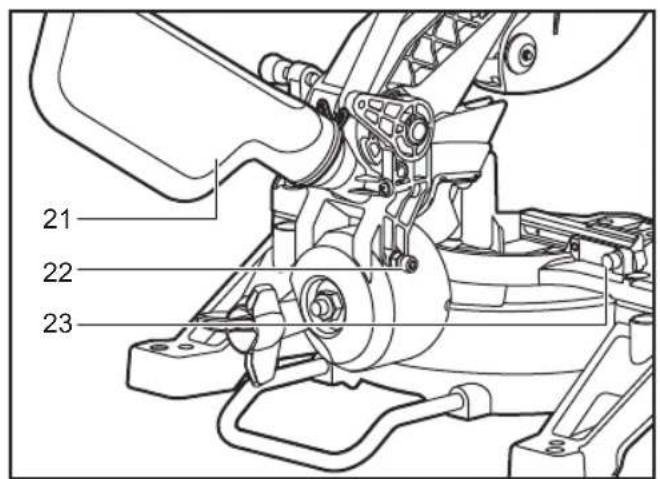
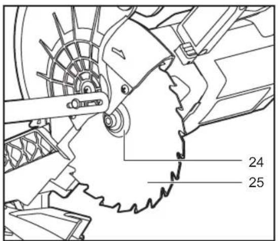
Mount saw blade:
If necessary, clean all parts to be mounted prior to assembly.
After following the procedure to "Remove Saw Blade".
- Wear gloves when handling the saw blade.
- Ensure the power is off and the battery pack is removed
- Swing back the self-closing guard, and hold it.
- Place the new saw blade. Ensure the rotation direction on the blade is consistent with the arrow direction on the blade guard.
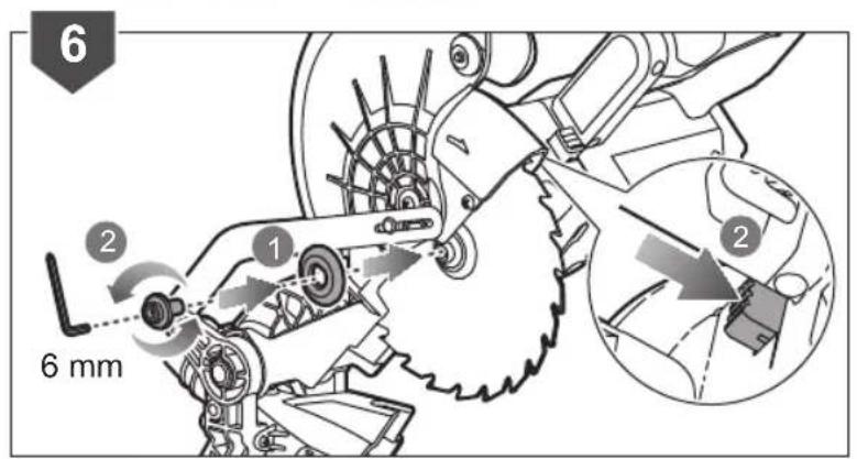
- Place on the flange and blade bolt.
- Press spindle lock button until it engages, tighten the blade bolt.
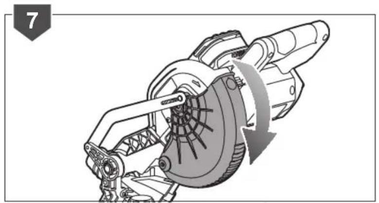
- Put the self-closing guard down.
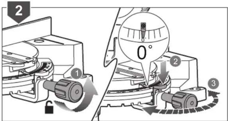
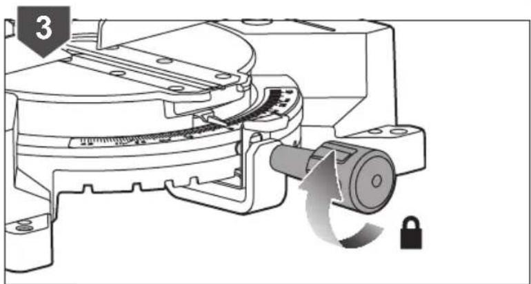
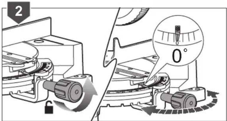
Adjust mitre angle:
The mitre angle can be set in the range from 45 degree (left side) to 45 degree (right side).
- Loosen the mitre lock knob.
- Press mitre detent release lever. Turn the saw table to desired mitre angle by the mitre lock knob.
- Tighten the mitre lock knob again.
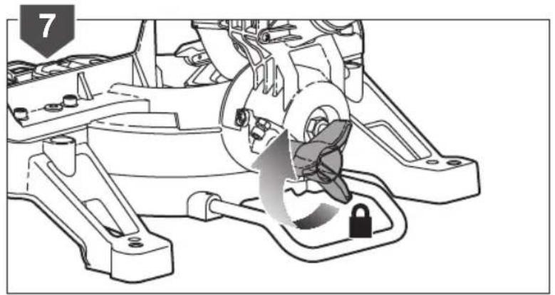
Adjust bevel angle:
The bevel angle can be set in the range from 0 degree to 45 degrees.
- Loosen bevel lock knob.
- Tilt the tool arm to desired bevel angle by the handle
- Hold the tool arm in this position and retighten the bevel lock knob.
WARNING
The manufacturer strongly recommends that the product is always securely mounted to a bench top.
When the base of the product is firmly secured to a bench top by four nuts, bolts and washers as instructed, the product can be used at maximum bevel and mitre setting without the possibility of it tipping over. If the product is not secured properly, the product may over balance when large bevel angles are selected.
MAINTENANCE
- Do not modify the product in any way or use accessories not approved by the manufacturer. Your safety and that of others may be compromised.
- Do not use the product if any switches, guards or other functions does not work as intended. Return to an authorised service centre for professional repair or adjustment.
- Do not make any adjustments whilst the saw blade is in motion.
■ Always make sure the battery pack has been removed from the product before making adjustments, lubricating or when doing any maintenance on the product.
■ Before and after each use, check the product for damage or broken parts. Keep the product in top working condition by immediately replacing parts with spares approved by the manufacturer.
■ The blade has sharp edges and may also remain hot after cutting operations. Exercise extreme caution when cleaning an exposed blade. Wear gloves to protect yourself from personal injury.
- Clean the saw and its accessories from dust regularly, especially moving parts including the blade guard. Use a hand brush or vacuum cleaner to remove dust effectively. Do not use compressed air.
■ To assure safety and reliability, all repairs, including changing brushes, should be performed by an authorised service centre.
WARNING
Do not attempt to disassemble the blade guard assembly for cleaning or repair. Damaged guards should not be used. Return to an authorised service centre for repair or replacement.
WARNING
For greater safety and reliability, all repairs should be performed by an authorised service centre.
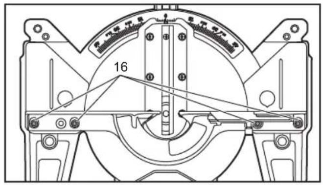
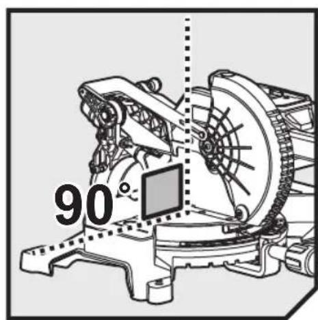
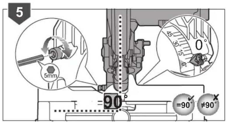
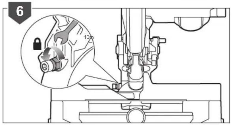
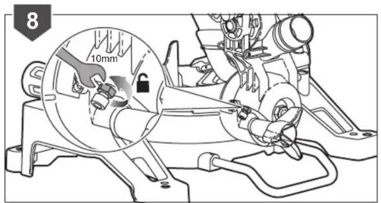
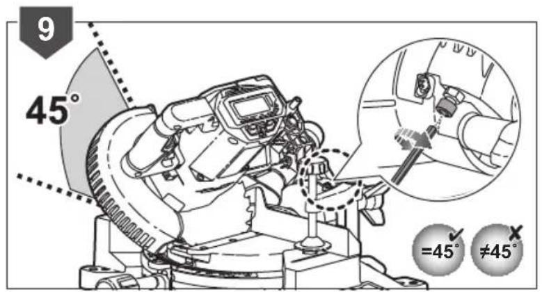
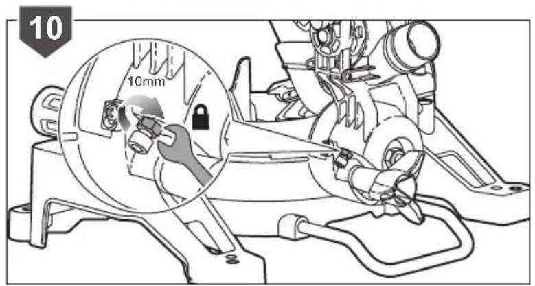
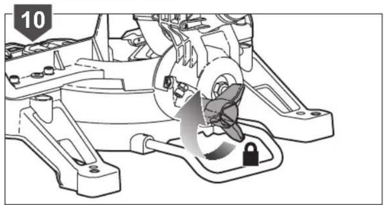
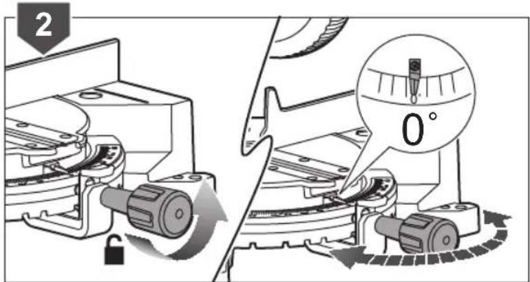
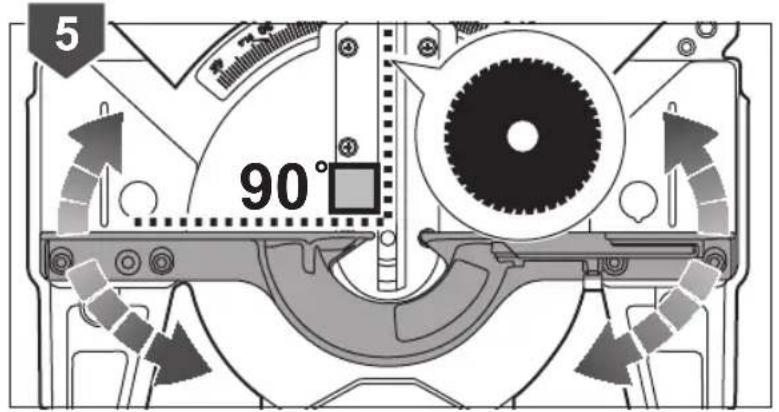
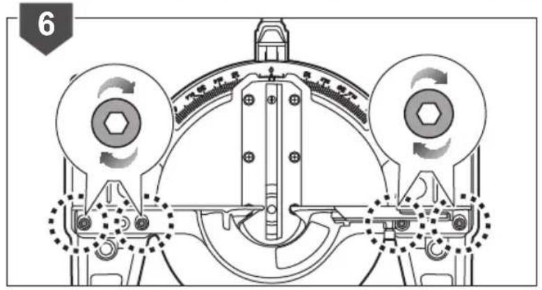
Mitre and bevel angle calibration
If mitre and bevel angle calibration are needed, see pages 232 - 238 and follow the calibration instructions.
TRANSPORTATION AND STORAGE
- When storing the product, remove the battery pack. Store the product in a secure place that is not accessible to children.
■ Clean the product using a brush and vacuum cleaner before storage.
If you remove the saw blade or keep spares with the unit, ensure they are in the original packaging to prevent injury.
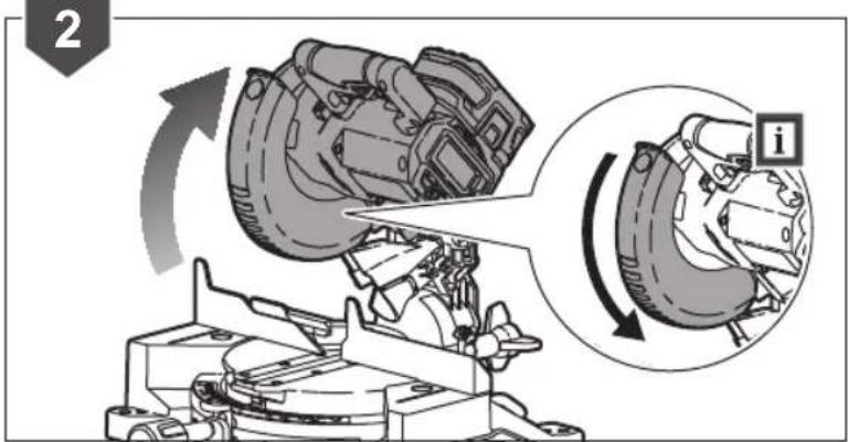
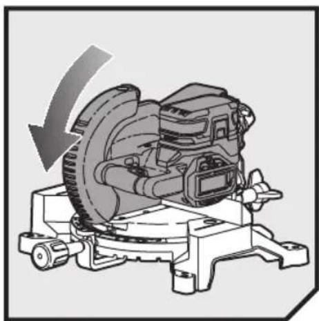
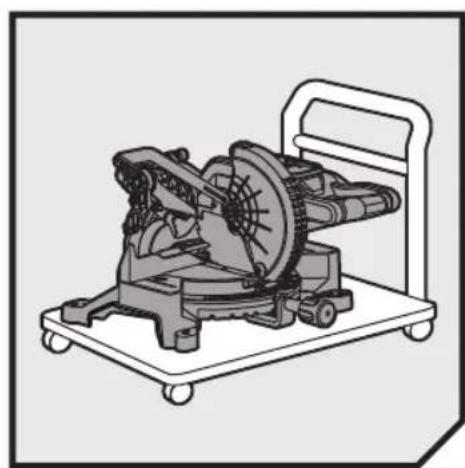
To secure the product prior to movement:
The product should be stored at the zero degree mitre and bevel angle and locked in position. The handle should be locked in the lower (safe) position with the guards closed.
To move or transport in a vehicle:
- Secure the product prior to movement as described in the manual.
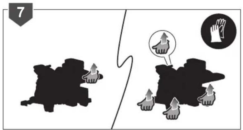
■ Remove the product from the bench top by releasing the 4 bolts, one at each corner. Secure the bolts for future use. When lifting to a height, two persons wearing heavy gloves are needed to lift the base of the product.
■ When transporting in a vehicle, set the product on its base and secure against movement.
ENVIRONMENTAL PROTECTION
Recycle raw materials instead of disposing of as waste. The machine, accessories and packaging should be sorted for environmental-friendly recycling.
SYMBOLS ON THE PRODUCT


Safety alert
CE conformity
EurAsian conformity mark
Ukrainian mark of conformity
Please read the instructions carefully before starting the machine.
Wear ear protection
Always wear eye protection.
Keep hands away from the cutting area and sharp blade.
Do not expose to rain or use in damp locations.
Wear safety gloves
Blade rotation direction (shown on saw blade)
Blade rotation direction (shown on blade guard)
Blade width of cut (Kerf)
Number of teeth on this saw blade
Cutting capacity
For cutting wood and analogous material

Not for cutting metals
Adjust the position of sliding fence before performing bevel or compound cuts.
Waste electrical products should not be disposed of with household waste. Please recycle where facilities exist. Check with your Local Authority or retailer for recycling advice.
SYMBOLS IN THIS MANUAL

Lock

Unlock

Waiting time for blade to reach full speed or stop completely

Parts or accessories sold separately

Note

Warning
The following signal words and meanings are intended to explain the levels of risk associated with this product:

DANGER
Indicates an imminently hazardous situation, which, if not avoided, will result in death or serious injury.

WARNING
Indicates a potentially hazardous situation, which, if not avoided, could result in death or serious injury.

CAUTION
Indicates a potentially hazardous situation, which, if not avoided, may result in minor or moderate injury.
CAUTION
(Without Safety Alert Symbol) Indicates a situation that may result in property damage.
SYMBOLES APPLIQUÉS SUR LE PRODUIT


Alerte de sécurité
Conformité CE
MACHEN SIE SICH MIT IHREM PRODUKT VERTRAUT
Siehe Seite 217.
SYMBOLE AUF DEM PRODUKT

Sicherheitswarnung

CE Konformität

SYMBOLER PÅ PRODUKTET

Sikkerhedsadvarsel

CE-overensstemmelse

TRANSPORT OCH FÖRVARING
SYMBOLER PÅ PRODUKTEN

Säkerhetsvarning

CE-överensstämmelse

SYMBOLER I MANUALLEN

Lás

Lås upp

SIKKERHET PÅ ARBEIDSOMRÅDET
VEDLIKEHOLD OG OPPBEVARING
Fjern batteriet fra sagen när sagen skal lagres. Oppbevar maskinen på et trygt sted der barn ikke har tilgang.
■ Rengjør produktet med en børste eller støvsuger før det settes bort for lagring.
■ Hvis du fjerner sagbladet eller har reserveblader sammen med enheten, påse at de er pakket i originalemballasjen for å unngå skader.
SYMBOLER PÅ PRODUKTET

Sikkerhetsadvarsel

CE samsvarserklæring

EurAsian Konformitetstegn

Ukrainsk merke for konformitet

ÜLDISED OHUTUSREEGLID
HDIATUS
NURGASAAGIDE OHUTUSJUHISED
DODATNA VARNOSTNA OPOZORILA
OBOZNÁMTE SA S VAŠÍM PRODUKTOM
alepo Vid' strana 217.
mayinoz Batarya kutusu
natural_image
Technical line drawing of a mechanical device with gears and levers, shown with a small inset image labeled 'x1' (no text or symbols on the diagram itself)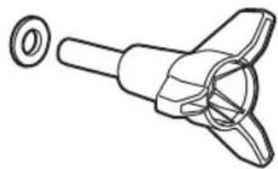
natural_image
Technical line drawing of a mechanical component with a central hub and a separate circular inset (no text or symbols)
natural_image
Simple line drawing of a mechanical lever with a flanged base and a cylindrical shaft, labeled 'x1' (no text or symbols on the diagram itself)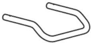
natural_image
Simple line drawing of a U-shaped object (no text or symbols)
x 2x 1
natural_image
Simple line drawing of a bag with a handle and spout (no text or symbols)x1
x1
natural_image
Mechanical assembly diagram showing a motor or gear mechanism with rotating components and an upward arrow indicating motion (no text or symbols present)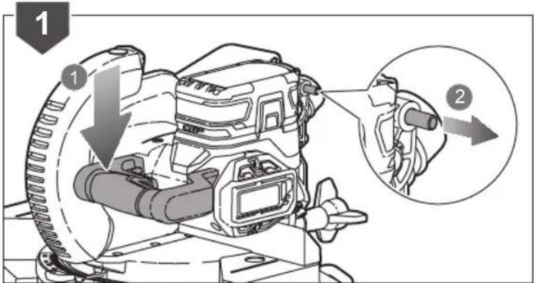
natural_image
Mechanical assembly diagram showing a gear and motor components with a downward arrow indicating motion (no text or symbols present)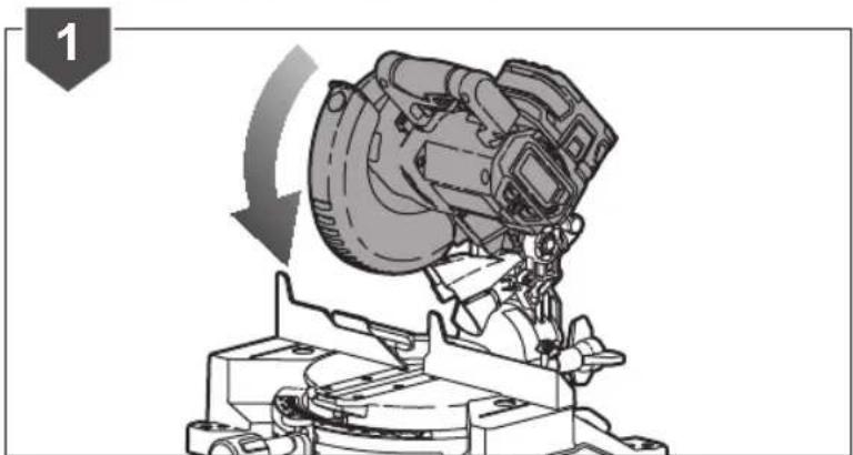
natural_image
Mechanical assembly diagram showing a rotating device mounted on a workbench, with no visible text or symbols.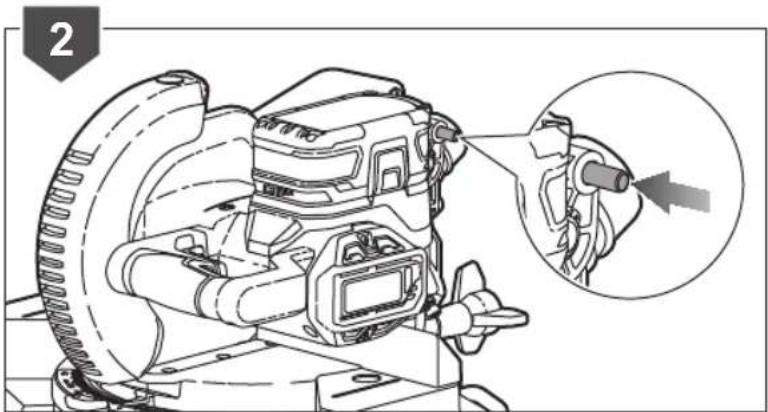
natural_image
Technical line drawing of a mechanical device with a magnified inset showing a component detail (no text or symbols)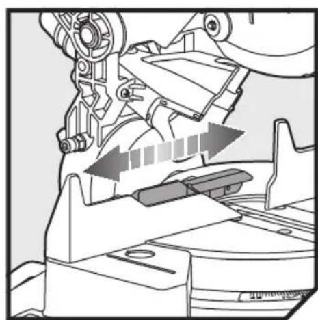
natural_image
Mechanical assembly diagram showing gear and lever mechanism with directional arrows (no text or symbols)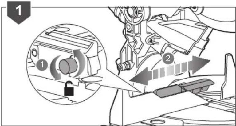
natural_image
Mechanical assembly diagram showing a gear shift mechanism with a close-up inset of the component (no text or symbols)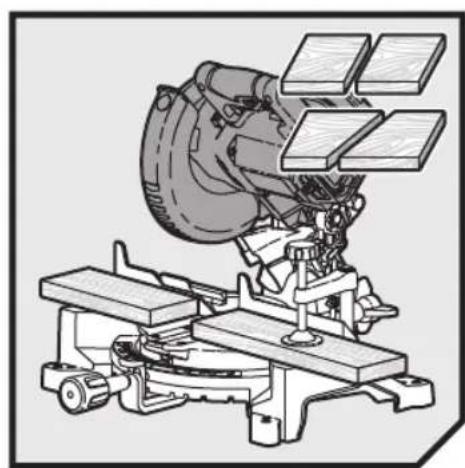
natural_image
Technical illustration of a mechanical device with multiple components mounted on a base (no visible text or symbols)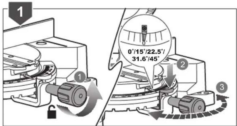

natural_image
Mechanical assembly diagram showing a lock mechanism with a valve and directional arrow (no text or symbols)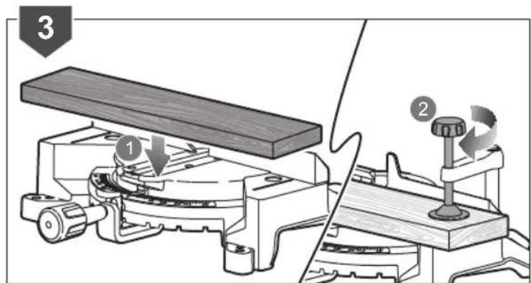
natural_image
Technical line drawing of a mechanical assembly with wooden base and mounting bracket (no text or symbols)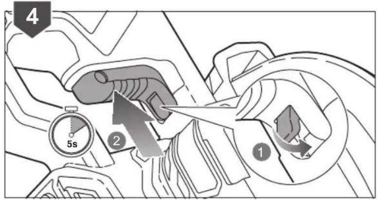
natural_image
Mechanical assembly diagram showing a gear and motor components (no text or symbols)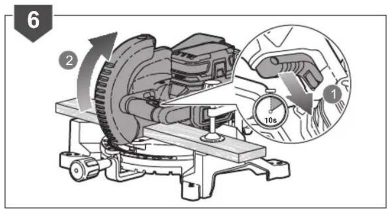
natural_image
Illustration of a cutting machine with a wooden block structure overlay (no text or symbols)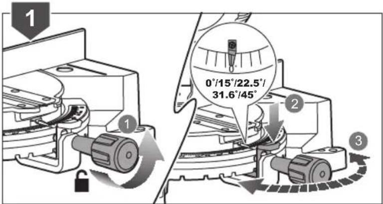

natural_image
Mechanical assembly diagram showing a lock mechanism with a curved arrow indicating rotation (no text or symbols present)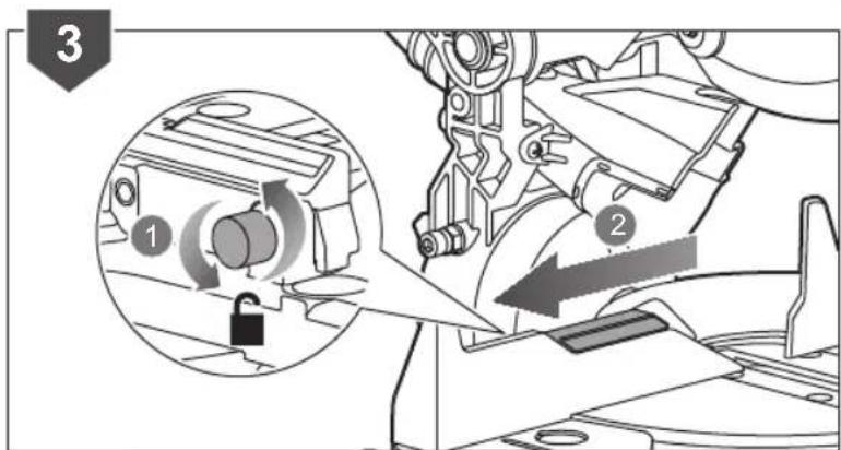
natural_image
Mechanical assembly diagram showing a lock mechanism inside a housing with an inset close-up of the component (no text or symbols)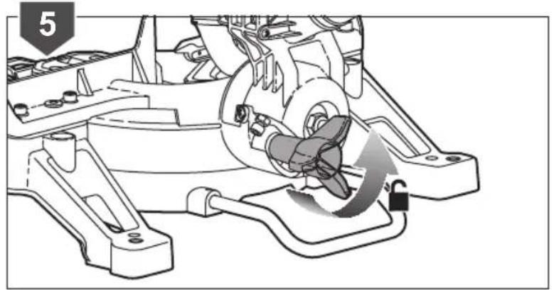
natural_image
Mechanical assembly diagram showing a gear shift mechanism with no visible text or symbols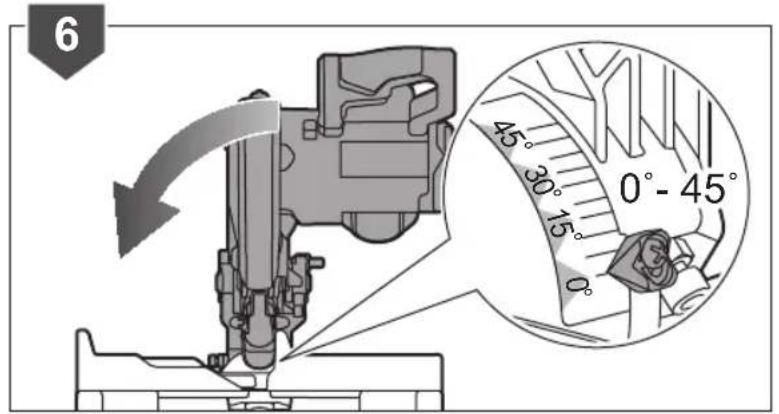
natural_image
Mechanical assembly diagram showing a rotating component with a lock and curved arrow indicating motion (no text or symbols)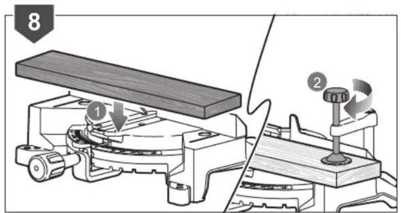
natural_image
Mechanical device with a rotating arm and base mount, no visible text or symbols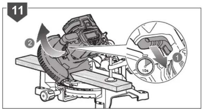
natural_image
Mechanical diagram showing a cutting machine with a blade and rotating wheel (no text or symbols)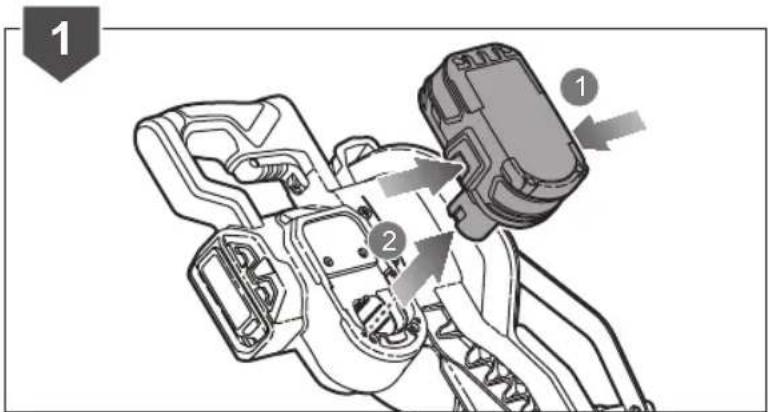
natural_image
Technical illustration of a cutting tool with a blade and cutter (no text or symbols)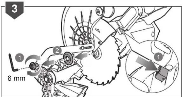
natural_image
Technical line drawing of a mechanical assembly with gears and linkages (no text or symbols)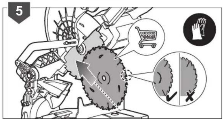
natural_image
Mechanical assembly diagram showing a cutting tool and gear mechanism with no visible text or symbols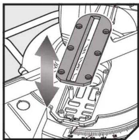
natural_image
Mechanical assembly diagram showing a component with an upward arrow indicating motion or force (no text or symbols present)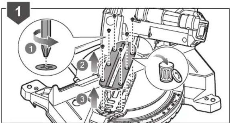
natural_image
Mechanical assembly diagram showing a lock mechanism with a curved arrow indicating rotation (no text or symbols present)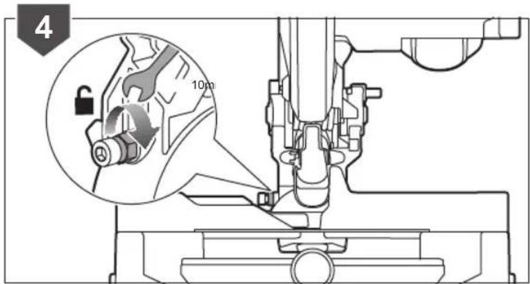


natural_image
Mechanical assembly diagram showing a piston and lock mechanism (no text or symbols)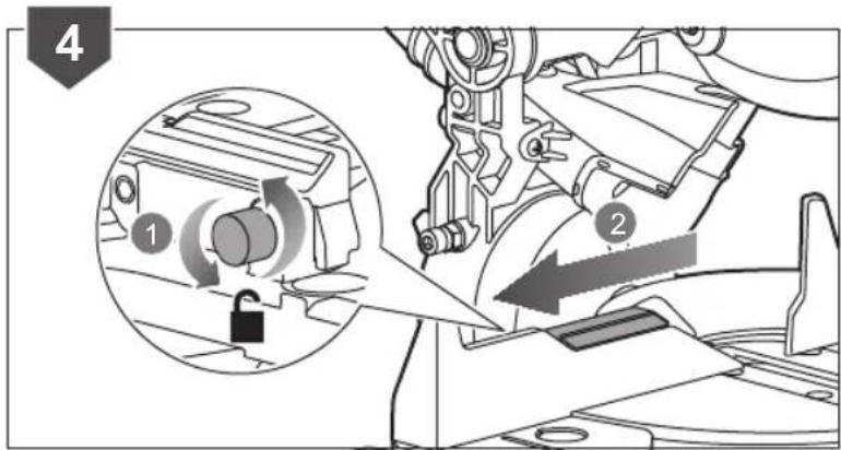
natural_image
Mechanical assembly diagram showing a gear shift mechanism with a close-up inset of the component (no text or symbols)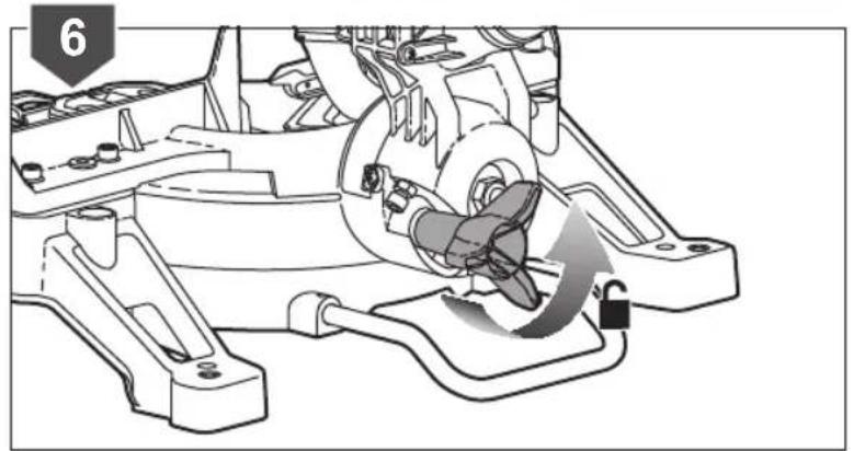
natural_image
Mechanical assembly diagram showing a motor and gear assembly with a lock mechanism (no text or symbols)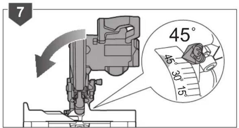
natural_image
Mechanical assembly diagram showing a rotating component with a lock and gear mechanism (no text or symbols)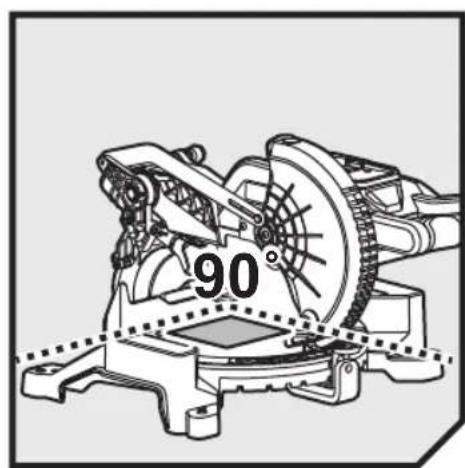
natural_image
Technical illustration of a mechanical device with a 90-degree angle标注 (no readable text or symbols)

natural_image
Mechanical assembly diagram showing a piston and lock mechanism (no text or symbols)
natural_image
Illustration of a mechanical device on a wheeled platform (no text or symbols visible)

natural_image
Mechanical assembly diagram showing a piston mechanism with directional arrows and a lock, no text or symbols present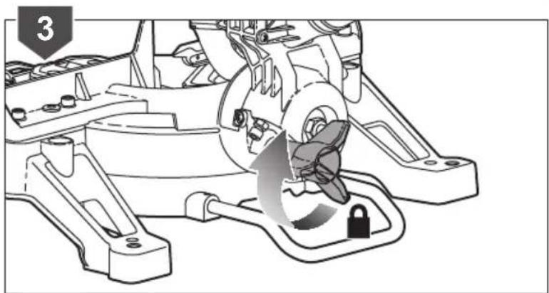
natural_image
Mechanical assembly diagram showing a rotating component with a lock and gear mechanism (no text or symbols)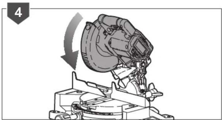
natural_image
Mechanical assembly diagram showing a rotating component with a curved arrow indicating motion (no text or symbols)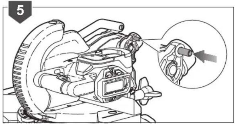
natural_image
Technical line drawing of a mechanical assembly with an inset close-up showing a component (no text or symbols present)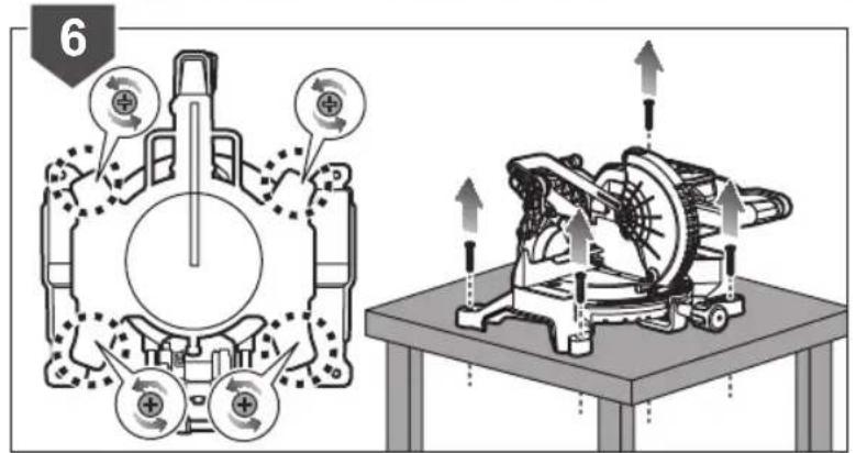


| EnglishFrançaisDeutschEspañolItalianoNederlandsPortuguês | ||||||
| Product specifications | Caractéristiques de l'appareil | Produkt-Spezifikationen | Especificaciones del producto | Specifiche prodotto Products | specificaties Especificações do produto | |
| Mitre saw Scie à onglet Gehungskappsäge Ingletadora Sega per tagli obliqui Verstekzaag Serra de esquadria | ||||||
| Model Modèle Modell | Modelo Modello | Modelo | Modelo | |||
| Net weight | Poids net | Nettogewicht | Peso neto | Peso netto | Nettogewicht | Peso líquido |
| Blade diameter | Diamètre du disque de coupe | Sägeblattdurchmesser | Diámetro de la hoja | Diametro lama | Zaagbladdiameter | Diâmetro da lâmina |
| Arbor hole | Trou de broche | Aufnahmebohrung | Hueco del eje | Foro dell'albero | Asgat | Orificio do eixo |
| Blade teeth | Nombre de dents | Sägezähne | Dientes de la hoja | Denti lame | Zaagbladtanden | Dentes da lâmina |
| Width of cut | Largeur de coupe | Breite des Schnitts | Ancho del corte | Ampiezza di taglio | Maalbreedte | Largura do corte |
| No-load speed r/min. (RPM) | Vitesse à vide tr/min (tr.min-1) | Leerlaufdrehzahl U/min | Velocidad sin carga r/min. (RPM) | Velocità a vuolo r/min. (RPM) | Onbelast toerental t/min. (TPM) | Velocidade em vazio r/min. (RPM) |
| Input | Alimentation | Spannung | Cargador | Alimentazione | Input | Admissão |
| Cutting capacity | Capacité de coupe | Schnittleistung | Capacidad de corte | Capacità di taglio | Zaagcapaciteit | Capacidade de corte |
| Mitre 0° x bevel 0° | Onglet 0° x biseau 0° | Gehrung 0° x Neigung 0° | Inglete 0° x bisel 0° | Angolazione 0° x smussatura 0° | Verstek 0° x afschuining 0° | Esquadria 0° x bisel 0° |
| Mitre 0° x bevel 45° | Onglet 0° x biseau 45° | Gehrung 0° x Neigung 45° | Inglete 0° x bisel 45° | Angolazione 0° x smussatura 45° | Verstek 0° x afschuining 45° | Esquadria 0° x bisel 45° |
| Mitre 45°(Left) x bevel 0° | Onglet 45°(Gauche) x biseau 0° | Gehrung 45°(Links) x Neigung 0° | Inglete 45° (izquierda) x bisel 0° | Angolazione 45°(Sinistra) x sussatura 0° | Verstek 45° (links) x afschuining 0° | Esquadria 45° (esquerda) x bisel 0° |
| Mitre 45°(Right) x bevel 0° | Onglet 45°(Droit) x biseau 0° | Gehrung 45°(Rechts) x Neigung 0° | Inglete 45° (derecha) x bisel 0° | Angolazione 45°(Destra) x smussatura 0° | Verstek 45° (rechts) x afschuining 0° | Esquadria 45° (direita) x bisel 0° |
| Mitre 45°(Left) x bevel 45° | Onglet 45°(Gauche) x biseau 45° | Gehrung 45°(Links) x Neigung 45° | Inglete 45° (izquierda) x bisel 45° | Angolazione 45°(Sinistra) x sussatura 45° | Verstek 45° (links) x afschuining 45° | Esquadria 45° (esquerda) x bisel 45° |
| Mitre 45°(Right) x bevel 45° | Onglet 45°(Droit) x biseau 45° | Gehrung 45°(Rechts) x Neigung 45° | Inglete 45° (derecha) x bisel 45° | Angolazione 45°(Destra) x smussatura 45° | Verstek 45° (rechts) x afschuining 45° | Esquadria 45° (direita) x bisel 45° |
| Min. workpiece dimensions | Dimensions min. de la pièce | Min. Werkstückabmes-sungen | Dimensiones min. de la pieza de trabajo | Min. misurazione massima dei pezzi | Min. werkstukafmeting | Dimensões min. da peça de trabalho |
| Measured values determined according to EN 62841 A-weighted sound pressure level | Valeurs mesurées obtenues selon EN 62841 Niveau de pression sonore pondérée-A | Gemäß EN 62841 gemessene Werte A-bewerteter Schalldruckpegel | Valores medidos determinados de acuerdo con EN 62841 Nivel de presión acústica ponderada en A | Valori misurati determinati in accordo con lo standard EN 62841 Livello di pressione sonora pesato A | Valeurs mesurées obtenues selon EN 62841 A-gewogen geluidsdrukniveau | Valores medios calculados de acordo com EN 62841 Nivel de pressão sonora ponderada A |
| Uncertainty K | Incertitude K | Unsicherheit K | Incertidumbre K | Incertezza K | Onzekerheid K | Incerteza K |
| Measured values determined according to EN 62841 A-weighted sound power level | Valeurs mesurées obtenues selon EN 62841 Niveau de puissance sonore pondérée-A | Gemäß EN 62841 gemessene Werte A-bewerteter Schalleistungspegel | Valores medidos determinados de acuerdo con EN 62841 Nivel de potencia acústica ponderada en A | Valori misurati determinati in accordo con lo standard EN 62841 Livello di potenza sonora pesato A | Valeurs mesurées obtenues selon EN 62841 A-gewogen geluidsniveau | Valores medios calculados de acordo com EN 62841 Nivel de potência sonora ponderada A |
| Uncertainty K | Incertitude K | Unsicherheit K | Incertidumbre K | Incertezza K | Onzekerheid K | Incerteza K |
| Replacement parts: | Pièces de rechange: | Ersatzteile: | Piezas de repuesto: | Parti di ricambio: | Vervangonderdelen: | Peças de substituição: |
| Saw blade | Lame de scie | Sägeblatt | Cuchilla de la sierra | Lama sega | Zaagblad | Lâmina da serra |
| Kerf plate | Plaque de trait de scie | Schnittplatte | Placa de corte | Piastra intagliata | Kerfplaat | Placa de corte |
| Outer flange | Flasque extérieur | Äußerer Flansch | Reborde exterior | Flangia estema | Buitenflens | Flange externa |
| Dust bag | Sac à poussière | Staubauffangeinrichtung | Bolsa para el polvo | Sacchetto per la polvere | Stofzak | Saco para o pó |

| DanskSvenskaSuomiNorskPycckii | Polski | |||||
| Produktspecifikationer Produktspecifikationer | Tuotteen teknisettiedot | Produktspesifikasjoner Xapakteristikni udelingia Paramery techniczne | ||||
| Geringssav Geringssag Viistesana Gjærsag Topuovo-ycovohna nila Pilarka ukosowa | ||||||
| Model | Modell | Malli | Modell | Modelb | Model | EMS190DC |
| Nettovægt | Nettovikt | Kokonaispaino | Nettovekt | Bec netto | Masa netto | 7,9 kg |
| Klingediameter | Klingdiameter | Terän lăpimitta | Bladdiameter | Diametr pejungero dicska | Średnica tarczy tnącej | 190 mm |
| Spindelhul | Spindelhål | Karan reikä | Spindelhull | Pabocce otberstie | Otwör trzpienia | 30 mm |
| Klingetaender | Sågland | Terän hampaat | Bladtenner | Число зубьев | Liczba zebów tarczy | 24 |
| Snitbredde | Skärbredd | Leikkauksen leveys | Bredde på kappet | Ширina paizreza | Szerokość cięcia | 2,3 mm |
| Tomgangshastighedomdr/min. (RPM) | Tomgangshastighetv/min (varv per minut) | Tyhjäkäyntinopeuskierr/min (RPM) | Hastighet ubelasleto/min. (RPM) | Скорость на xolostom xodyob/min | Prędkość bez obciążeniacobr./min. (RPM) | 4200 |
| Strømforsyning | Matningsspänning | Virrankulutus | Input | Питане | Zasilanie | 18V |
| Savekapacitet | Skärkapacitet | Leikkuukapasiteetti | Sagekapasitet | Pegущая spocobnostb | Zakres możlwości cięcia | |
| Gering 0° x smig 0° | Lutning 0° x vinkel 0° | Viiste 0° x sarmä 0° | Gjæsring 0° x skrákant 0° | Yogł noporota 0° x yoglnakłona 0° | Ukos 0° x skos 0° | 45 mm x 108 mm |
| Gering 0° x smig 45° Lutning 0° | x vinkel 45° Viste 0° x sarmä 45° | Viiste 45° (vasen) xsarmä 0° | Gjæsring 0° x skrákant 45° | Yogł noporota 0° x yoglnakłona 45° | Ukos 0° x skos 45° | 35 mm x 108 mm |
| Gering 45°(venstre) x smig 0° | Lutning 45 (vänster) x vinkel 0° | Viiste 45° (vasen) xsarmä 0° | Gjæsring 45°(venstre) xskrákant 0° | Yogł noporota 45°(blevo) xyogł nacklona 0° | Ukos 45°(w lewo) x skos 0° | 45 mm x 76 mm |
| Gering 45°(højre) x smig 0° | Lutning 45 (höger) x vinkel 0° | Viiste 45° (oikea) xsarmä 0° | Gjæsring 45°(høyre) xskrákant 0° | Yogł noporota 45°(wpravo) xyogł nacklona 0° | Ukos 45°(w prawo) x skos 0° | 45 mm x 76 mm |
| Gering 45°(venstre) x smig 45° | Lutning 45 (vänster) x vinkel 45° | Viiste 45° (vasen) xsarmä 45° | Gjæsring 45°(venstre) xskrákant 45° | Yogł noporota 45°(blevo) xyogł nacklona 45° | Ukos 45°(w lewo) x skos 45° | 35 mm x 76 mm |
| Gering 45°(højre) x smig 45° | Lutning 45 (höger) x vinkel 45° | Viiste 45° (oikea) xsarmä 45° | Gjæsring 45°(høyre) xskrákant 45° | Yogł noporota 45°(wpravo) xyogł nacklona 45° | Ukos 45°(w prawo) x skos 45° | 35 mm x 76 mm |
| Min. mal på arbejdsemner | Min. avmätning avarbetsstycket | Työkappaleonminimaalinen | Min. verktayma | Minimalnybrial paamеры | Min. wymiary przedmiotuobrabianego | 130 mm x 35 mm x 2,5 mm |
| Mälte vaerdier bestemmes i henhold til EN 62841A-vægtet lydtryksniveau | Värden uppmälta enligtEN 62841A-vägd ljudtrycksniva | Mitatut arvotmäintetty EN 62841-standardin mukaanA-painotettuaänenpainetaso | Mälte verdier i samsvarmed EN 62841A-vektet lydtrykkniva | Измереньe zhaheniaopredeleny b cootretstviinc EN 62841Uroveny A-vzvewnho#o zbykovoro давlenia | Zmierzone wartosci okreslonewg EN 62841A-wazony poziom ciśnienialahasu | L_pa = 90,0 dB(A) |
| Usikkerhed K | Osäkerhet K | Epätarkkuus K | Usikkerhet K | Pazbros K | Niepewnosć pomiaru K | 3 dB(A) |
| Mälte vaerdier bestemmes i henhold til EN 62841A-vägtet lydfeffektniveau | Värden uppmälta enligtEN 62841A-vägd ljudeffektsniva | Mitatut arvotmäintetty EN 62841-standardin mukaanA-painotettuaänenpahetao | Mälte verdier i samsvarmed EN 62841A-vektet lydfeffektniva | Измереньe zhaheniaopredeleny b cootretstviinc EN 62841Uroveny A-vzvewnho#o zbykovoro maushosti | Zmierzone wartosci okreslonewg EN 62841A-wazony poziom natężeniialahasu | L_pa = 103,0 dB(A) |
| Usikkerhed K | Osäkerhet K | Epätarkkuus K | Usikkerhet K | Pazbros K | Niepewnosć pomiaru K | 3 dB(A) |
| Reservedele: | Utbytesdelar: | Varaosat: | Reservedeler: | Заласные части: | Częsci zamienne: | |
| Savklinge | Sågblad | Sahanterä | Sagblad | Пильhoe полотно | Tarcza tnąca | 5131042439 |
| Snitplade | Platta för sagsnitt | Kerf-levy | Kantplate | Torцевaa plastina | Wstawka stolowa | 5131042440 |
| Yderflange | Yttre fläns | Ulkolaippa | Utvendig sidestykke | Внеший flanecc | Kohierz zewnetrzny | 5131042441 |
| Stavpose | Dammpase | Pölypussi | Stavpose | Пылесборный me##ok | Worek na pył | 5131042442 |

| Čeština | Magyar | Română | Latviski | Lietuviškai | Eesti |
| Technické údaje produktu | Termék műszaki adatai | Specificațile produsului | Produkta specifikácijas | Gaminio techninės savybės | Toote tehnilised andmed |
| Pokosová pila Cérvágó fűrész F | Ferästräu unghiular Lenjzágis | Skersinis pjūklas Miusaag | |||
| Model | Típus | Model | Modelis | Modelis | Mudeli tāhis |
| Čistá hmotnost | Nettó tömeg | Greutate netă | Svars neto | Neto svoris | Netomass |
| Prümér kotouče | Tárcsa átmérője | Diametru lamă | Asmens diamets | Pjovimo disko skersmuo | Saeketta läbimõõt |
| Otvor hřidele | Tengelyfurat | Orficiu arbore | Värpstas atvere | Ašies anga | Võlliava |
| Zub kotouče | Fürészlap fogai | Dinte lamà | Asmens zobi | Geležtės dantukų skaičius | Lõiketera hammas |
| Širka řezu | Vágás szėlessége | Látjme a täierii | Griezuma platums | Pjovimo plotis | Lõikelaius |
| Otáčky naprázdno ot./min. (RPM) | Üresjáratí fordulatszám ford./perc (RPM) | Viteză în gol rot/min. (RPM) | Apgriezieni bez slodzes apgr./min. (RPM) | Greitis be apkrovimo aps./min. (apsukų per minutę) | Klirus ilma koormuseta p/min. (p/min) |
| Vstup | Bemenet | Intrare | Ieeja | Ivestis | Vooluvõrk |
| Maximální profez | Vágásteljesítmény | Capacitate de täiere | Zägėšanas ražība | Pjovimo talpa | Lõikesügavu |
| Pokos 0° x úkos 0° | Gérvágás 0° x ferdevágás 0° | Unghi 0° x täietură la 0° | Lenkis 0° x slīpums 0° | Užkarpa 0° x nuožambis 0° | Kaldlõige 0° x nurklõige 0° |
| Pokos 0° x úkos 45° | Gérvágás 0° x ferdevágás 45° | Unghi 0° x täietură la 45° | Lenkis 0° x slīpums 45° | Užkarpa 0° x nuožambis 45° | Kaldlõige 0° x nurklõige 45° |
| Pokos 45°(vlevo) x úkos 0° | Gérvágás 45°(bal) x ferdevágás 0° | Unghi de 45°(Stânga) x täietură la 0° | Lenkis 45°(pa kreisi) x slīpums 0° | Užkarpa 45°(kairėje) x nuožambis 0° | Kaldlõige 45° (vasak) x nurkõige 0° |
| Pokos 45°(vpravo) x úkos 0° | Gérvágás 45°(jobb) x ferdevágás 0° | Unghi de 45°(Dreapta) x täietură la 0° | Lenkis 45°(pa labi) x slīpums 0° | Užkarpa 45°(dešinėje) x nuožambis 0° | Kaldlõige 45° (parem) x nurkõige 0° |
| Pokos 45°(vlevo) x úkos 45° | Gérvágás 45°(bal) x ferdevágás 45° | Unghi de 45°(Stânga) x täietură la 45° | Lenkis 45°(pa kreisi) x slīpums 45° | Užkarpa 45°(kairėje) x nuožambis 45° | Kaldlõige 45° (vasak) x nurkõige 45° |
| Pokos 45°(vpravo) x úkos 45° | Gérvágás 45°(jobb) x ferdevágás 45° | Unghi de 45°(Dreapta) x täietură la 45° | Lenkis 45°(pa labi) x slīpums 45° | Užkarpa 45°(dešinėje) x nuožambis 45° | Kaldlõige 45° (parem) x nurkõige 45° |
| Min. rozměry obrobku Min. mun | cadarab méretek | Dimensiunile minimă ale piesei de prelucrat | Min. apstrādājamās detaljas izmērs | Min. apdorojamos detalės matmenys | Min. tooriku mõõtmed |
| Naměřené hodnoty zjištěné dle EN 62841Hladina akustického tlaku vážená funkci A | A mért értékek meghatározása az EN 62841 szerint történtA-súlyozotthangnyomásszint | Valori māsurate determinate in conformitate cu EN 62841Nivel de presiune acustică ponderată A | Izměrītās vērtības saskaņa ar EN 62841A-līmeņa skaņas spiediena līmenis | Ismatuotosios vertės nustatytos pagal EN 62841A svertinis garso slėgio lygis | Mõõteväärtused on kindlaks määratud vastavalt standardile EN 62841A-kaalutud helirõhu tase |
| Nejistota K | Bizonytalanság K | Incertitudine K | Kjūdas vērtība K | Nepastovumas K | Mõõtemääramatus K |
| Naměřené hodnoty zjištěné dle EN 62841Hladina akustického výkonu vážená funkci A | A mért értékek meghatározása az EN 62841 szerint történtA-súlyozotthangteljesítményszint | Valori māsurate determinate în conformitate cu EN 62841Nivel de putere acustică ponderată A | Izměrītās vērtības saskaņa ar EN 62841A-līmeņa skaņas jaudas līmenis | Ismatuotosios vertės nustatytos pagal EN 62841A svertinis garso galicos lygis | Mõõteväärtused on kindlaks määratud vastavalt standardile EN 62841A-kaalutud helivõimsuse tase |
| Nejistota K | Bizonytalanság K | Incertitudine K | Kjūdas vērtība K | Nepastovumas K | Mõõtemääramatus K |
| Náhradní díly: | Cserealkatrészek; | Piese de schimb; | Rezerves daļas: | Atsarginės detalės: | Asendusosad; |
| Pilový kotouč | Fürészlap | Lama ferästrăului | Zāga asmens | Pjūklo geležtė | Saeleht |
| Deska řezu | Körfürészlap | Plācuṭa cu fāgaṣ | Asmens ierobežotāja plāksne | Plokštė su ipjova | Lõikeplaat |
| Vnějši přiruba | Külső alátét | Flanṣa exterioarā | Ārējais atloks | Disko jungė | Ketta äārik |
| Sáček pro prach | Porzsák | Sac pentru praf | Putekļu soma | Dulkių maišelis | Tolmukott |


| HrvatskiSlovenskoSlovenčina България | українська мова | TürkçeЕллянікá | ||||
| Specifikacije proizvoda Specifikacije izdelka Špecifikacija | Спецификации на продукта | Технічні характеристики продукту | Ürün Özellikleri | Пробіахрафеїς Проївотос | ||
| Kutna pila Zajeralna žaga | Rozbrusovačka | циркуляр за рязане под ъгъл | Торцювальна пила Gönye | lesleresi | Кόппіс уя фалтооуває | |
| Model Model Model Moden Модель Молтетло | EMS190DC | |||||
| Neto ležina Neto teža Neto hmotnosť Нетно тетло | Bara нетто Net ajirlik Кобаро βάроє | 7,9 kg | ||||
| Promjer rezne ploče | Premer rezila | Priemer kotuča | Диаметър на острието | Діаметр леза | Віçak çарі | Дідметрос летібас |
| Otvor za vratilo | Izvrtna vretena | Otvor hriadeľa | Отвор на шпиндела | Отвір валу | Mil deliği | Отнă аръва |
| Zubi pile | Zobje rezila | Zúbky čepele | Зьби на острието | Зубці леза | Віçak dişleri | Дóvtia летібас |
| Širina reza | Širina rezanja | Širka rezu | Ширина на рязане | Ширина різу | Kesim genişliği | Плátос коппіс |
| Brzina bez opterećenja o/min (OKR/MIN) | Hitrost brez obremenitive vrt./min (RPM) | Rýchlost’ bez záťaže ot./min. | Скорост в ненатоварен режим обл./мин (RPM) | Швидкість без навантаження Обí’хв. (Оборотів за хвитину) | Bota hiz d/dak. (DDS) | Таутта ст кєв r/min. (RPM) |
| Ulaz | Vhod | Vstup | Входен волтаж | Бхідний | Giriş | Еістобос реємпатос |
| Kapacitet rezanja | Zmogljivost rezanja | Kapacita rezania | Капацитет на рязане | Ріжуча здатність | Kesim kapasitesi | Ікаво́тта коппіс |
| Kutna pila 0° x nagib 0° | Zajera 0° x nagib 0° Sklon | 0° x úkos 0° | Съединяване по ъгъл 0° x скосяване 0° | Укіс 0° x конус 45° | Gönye açısı 0° x Eğім açısı 0° | Фалтооува іа 0° x лојотомі 0° |
| Kutna pila 0° x nagib 45° | Zajera 0° x nagib 45° | Sklon 0° x úkos 45° | Съединяване под ъгъл 0° x скосяване 45° | Укіс 0° x конус 45° | Gönye açısı 0° x Eğім açısı 45° | Фалтооува іа 0° x лојотомі 45° |
| Kutna pila 45°(lijevo) x nagib 0° | Zajera 45°(levo) x nagib 0° | Sklon 0° (vlavo) x úkos 0° | Съединяване по ъгъл 45° (ляво) x скосяване 0° | Укіс 45°(вліво) x конус 0° | Gönye açısı 45°(Sol) x Eğім açısı 0° | Фалтооува іа 45°(Аріσтера) x лојотомі 0° |
| Kutna pila 45°(desno) x nagib 0° | Zajera 45°(desno) x nagib 0° | Sklon 0° (vpravo) x úkos 0° | Съединяване под ъгъл 45° (дяско) x скосяване 0° | Укіс 45°(вправо) x конус 0° | Gönye açısı 45°(Sağ) x Eğім açısı 0° | Фалтооува іа 45°(Деşi) x лојотомі 0° |
| Kutna pila 45°(lijevo) x nagib 45° | Zajera 45°(levo) x nagib 45° | Sklon 45° (vlavo) x úkos 45° | Съединяване по ъгъл 45° (ляво) x скосяване 45° | Укіс 45°(вліво) x конус 45° | Gönye açısı 45°(Sol) x Eğім açısı 45° | Фалтооува іа 45°(Аріσтера) x лојотомі 45° |
| Kutna pila 45°(desno) x nagib 45° | Zajera 45°(desno) x nagib 45° | Sklon 45° (vpravo) x úkos 45° | Съединяване под ъгъл 45° (дяско) x скосяване 45° | Укіс 45°(вправо) x конус 45° | Gönye açısı 45°(Sağ) x Eğім açısı 45° | Фалтооува іа 45°(Деşi) x лојотомі 45° |
| Minimalna dimenzije radnog predmeta | Minimalna izmere obđelovalnega kosa | Min. rozmery obrobku | Минимални размери на работния детайл | Мінімальні розміри заготовки | Minimum is parçasі boyutu | Елахистес біостаєєєєєєєєєєєєєєєєєєєєєєєєєєєєєєєєєєєєєєєєєєєєєєєєєєєєєєєєєєєєєєєєєєєєєєєєєєєєєєєєєєєєєєєєєєєєєєєєєєєє |
| Mjerene vrijednosti određene su prema EN 62841 | Izmerjene vrednosti določene v skladu s standardom EN 62841 | Namerané hodnoty určené podla EN 62841 | Измерени стойности, определени в съответствие с EN 62841 | Виміряні значення шуму визначаються відповідно до EN 62841:А-зважений рівень звукового тиску | EN 62841 ile uyumlu olarak belirlenen ölçülen değerlerA ajirlikli ses basinc seviyesi | Оі потологиємієєєєєєєєєєєєєєєєєєєєєєєєєєєєєєєєєєєєєєєєєєєєєєєєєєєєєєєєєєєєєєєєєєєєєєєєєєєєєєєєєєєєєєєєєєєєєєєєєєєс |
| Ponderirana razina tlaka zvuka | A-izmerjena raven zvočnega tlaka | Vážená A hladina akustického tlaku | ||||
| Neodređenost K | Nedoloč. K | Odchýlka K | Променливост К | Невизначеньсть К | Belirsizlik K | Аßebaiо́тта К |
| Mjerene vrijednosti određene su prema EN 62841 | Izmerjene vrednosti določene v skladu s standardom EN 62841 | Namerané hodnoty určené podla EN 62841 | Измерени стойности, определени в съответствие с EN 62841 | Вимиряні значення шуму визначаються відповідно до EN 62841:А-зважений рівень звукової потужності | EN 62841 ile uyumlu olarak belirlenen ölçülen değerlerA ajirlikli ses gücü seviyesi | Оі потологиємієєєєєєєєєєєєєєєєєєєєєєєєєєєєєєєєєєєєєєєєєєєєєєєєєєєєєєєєєєєєєєєєєєєєєєєєєєєєєєєєєєєєєє |
| Ponderirana razina zvučne snage | A-izmerjena raven zvočne moči | Vážená A hladina akustického tlaku | ||||
| Neodređenost K | Nedoloč. K | Odchýlka K | Променливост К | Невизначеньсть К | Belirsizlik K | Аßebaiо́тта К |
| Zamjena dijelova: | Nadomestni deli: | Náhradné diely: | Смяна на части: | Запасні частини: | Yedek parçalar: | Анталактика: |
| List pile | Rezilo žage | Čepel pily | Острие | Лезо пили | Testere bicağı | Астіба коппін |
| Ploča propilja | Vrezovalna ploščica | Platňa na zárezy | Плоча с разрез | Планка розрізування | Kertme plakası | Плáка kerf |
| Vanjska prinubnica | Kolutna prirobnica | Príruba disku | Външен фланец | Зовнішний фланець | Dış flanş | Ефштерикі флăвтца |
| Vrečica za prašinu | Vrečka za prah | Vrecko na prach | Торба за прах | Мішок для пилу | Toz torbasi | Закоўла ско́вніс |


| EnglishFrançaisDeutschEspañolItalianoNederlandsPortuguês | ||||||
| Battery and charger | Batterie et chargeur | Akku und Ladegerät | Bateria y cargador | Batteria e caricatore | Accu en lader | Bateria e carregador |
| Compatible battery pack (not included) | Pack batterie compatible (non compris) | Kompatible Akkus (nicht im Lieferumfang enthalten) | Packs de Batería compatibles (no incluido) | Gruppo batterie compatibile (non incluso) | Compatibel accupack (niet inbegrepen) | Baterias compatíveis (não incluida) |
| Lithium-Ion | Lithium-Ion | Lithium-Ionen | lón-litio | loni di litio | Lithium-ion | lão-Lítio |
| Compatible charger (not included) | Chargeur compatible (non compris) | Kompatibles Ladegerät (nicht im Lieferumfang enthalten) | Cargador compatible (no incluido) | Caricatore compatibile (non incluso) | Compatibele oplader (niet inbegrepen) | Carregador compatível (não incluida) |
| Čeština | Magyar | Română | Latviski | Lietuviškai | Eesti |
| Baterie a nabiječka | Akkumulátor és töltő | Baterie și încărcător | Akumulators un lădëtãjs | Baterija ir įkroviklis | Aku ja laadija |
| Kompatibilní akumulátor (nepříbalen) | Kompatibilis akkumulátor (nem tartozék) | Acumulatori compatibili (neinclus) | Saderīgu akumulatoru komplekts (nav kompl.) | Suderinamas baterijos paketas (nepridedama) | Ühilduvad akupaketid (ei ole komplektis) |
| Lithium iontový akumulátor | Litiumion | Litiu-Ion | Litija-jonu | Litis-jonas | Liitiumioon |
| Kompatibilní nabiječka (nepříbalen) | Kompatibilis töltő (nem tartozék) | Încărcător compatibil (neinclus) | Saderīgs lădëtãjs (nav kompl.) | Tinkamas įkroviklis (nepridedama) | Kasutatav laadija (ei ole komplektis) |

| DanskSvenskaSuomiNorskРусский Polski | ||||||
| Batteri og oplader | Batteri och laddare | Akku ja laturi | Batteri og lader | Батарея и зарядное устройство | Akumulator i ładowarka | |
| Kompatibelt batteri (medfølger ikke) | Kompatibelt batteripack (inte inkluderat) | Yhteensopiva akku (ei mukana) | Kompatible batteripakker (ikke inkludert) | Совместимая аккумуляторная батарея (не входит в комплект поставки) | Pasujące akumulatory (nie dołączona) | |
| Lithium-ion | Litiumjon | Litiumioni | Litium-Ion | Литий-ионная аккумуляторная батарея | Li-Ion | RB18L13 RB18L15 RB18L20 RB18L25 RB18L30 RB18L40 RB18L50 RB18L90 |
| Kompatibel oplader (medfølger ikke) | Passande laddare (inte inkluderat) | Yhteensopiva laturi (ei mukana) | Kompatibel lader (ikke inkludert) | Совместимое зарядное устройство (не входит в комплект поставки) | Odpowiednia ładowarka (nie dołączona) | BCL14181H BCL14183H RC18150 RC18627 RC18115 RC18120 RC18118C |
The declared noise emission value(s) have been measured in accordance with a standard test method of EN 62841-1 and EN 62841-3-9, and may be used for comparing one tool with another.
The declared noise value(s) may also be used in a preliminary assessment of exposure.
The noise emissions during actual use of the power tool can differ from the declared values depending on the ways in which the tool is used especially what kind of workpiece is processed.
Identify safety measures to protect the operator based on an estimation of exposure in the actual conditions of use (taking account of all parts of the operating cycle such as the times when the tool is switched off and when it is running idle in addition to the trigger time).
Wear hearing protection. Exposure to noise can cause hearing loss.

AVERTISSEMENT
The noise emissions during actual use of the power tool can differ from the declared values depending on the ways in which the tool is used especially what kind of workpiece is processed.
In addition to any statutory rights resulting from the purchase, this product is covered by a warranty as stated below.
- The warranty period is 24 months for consumers and commences on the date the product was purchased. This date has to be documented by an invoice or other proof of purchase. The product is designed and dedicated to consumer and private use only. So there is no warranty provided in case of professional or commercial use. This warranty applies only on new products.
- There is a possibility to extend for a part of the range (AC/DC) the warranty period over the period described above using the registration on the www.ryobitools.eu website. The eligibility of products for extended warranty is clearly displayed in stores and / or on packaging and is contained within the product documentation. The end user is required to register his/her newly-acquired products online within 30 days from the date of purchase. The end user may register for the extended warranty in his/her country of residence if listed on the online registration form where this option is valid. Furthermore, end users must give their consent to the storage of their personal data that is required to be entered online. They must also accept the terms and conditions. The registration confirmation receipt, which is sent out by e-mail, and the original invoice showing the date of purchase will serve as proof of the extended warranty.
- The warranty covers all defects of the product during the warranty period due to faults in workmanship or material at the purchase warranty is limited to repair and/or replacement and does not include any other obligations including but not limited to incidental or consequential damages. The warranty is not valid if the product has been misused, used contrary to the instruction manual, or has been incorrectly connected to a power supply. This warranty does not apply to:
– any damage to the product that is the result of improper or lack of maintenance
—any product that has been altered or modified
– any product where original identification (trade mark, serial number) markings have been defaced, altered or removed
– any damage caused by non-observance of the instruction manual
– any product not displaying the CE approval mark on the rating plate
– any product that has been attempted to be repaired by a non-authorised warranty service centre or without prior authorisation by Techtronic Industries
– any product connected to improper power supply (amps, frequency)
– any damage caused by external influences (water, chemical, physical, shocks) or foreign substances
– normal wear and tear spare parts
– inappropriate use, overloading of the tool
– use of non-approved accessories or parts
- Power tool accessories provided with the tool or purchased separately, including but not limited to screw driver bits, drill bits, abrasive discs, sand paper and blades, lateral guide, etc.
- Components (parts and accessories) subject to natural tear, including but not limited to service & maintenance kits, carbon brushes, bearings, chuck, SDS drill bit attachment or reception, power cord, auxiliary handle, transport carry case, sanding plate, dust bag, dust exhaust tube, felt washers, impact wrench pins & springs, etc.
- For servicing, the product must be sent or presented to a RYOBI authorised service station listed for each country in the following list of service station addresses. In some countries your local RYOBI dealer undertakes to send the product to the RYOBI service organisation. When sending a product to a RYOBI service station, the product should be safely packed without any dangerous contents such as petrol, marked with sender's address and accompanied by a short description of the fault.
- A repair / replacement under this warranty is free of charge. It does not constitute an extension or a new start of the warranty period. Exchanged parts or products become our property. In some countries delivery charges or postage will have to be paid by the sender. Your statutory rights arising from the purchase of the product remain unaffected
- This warranty is valid in the European Community, Switzerland, Iceland, Norway, Liechtenstein, Turkey and Russia. Outside these areas, please 6. contact your authorised RYOBI dealer to determine if another applies.
AUTHORISED SERVICE CENTRE
To find an authorised service centre near you, visit http://uk.rycheader/service-and-support/service-agents
FR RYOBI® CONDITIONS D'APPLICATION DE LA GARANTIE
DECLARATION OF CONFORMITY
Techtronic Industries GmbH
Max-Eyth-Straße 10, 71364 Winnenden, Germany
Herewith we declare that the product
Mitre Saw
Brand: RYOBI
Model number: EMS190DC
Serial number range: 47504501000001 - 47504501999999
is in conformity with the following European Directives and harmonised standards
2006/42/EC, 2014/30/EU, 2011/65/EU
EN 55014-1:2017; EN 55014-2:2015;
EN 62841-1:2015; EN 62841-3-9:2015+A11:2017
RoHS documentation is compiled according to EN 50581:2012

Todd Chipner
Sr. Director, Regulatory & Safety
Authorised to compile the technical file:
Alexander Krug, Managing Director
Techtronic Industries GmbH
Max-Eyth-Straße 10, 71364 Winnenden, Germany

DÉCLARATION DE CONFORMITÉ
Techtronic Industries GmbH
Max-Eyth-Straße 10, 71364 Winnenden, Germany
Max-Eyth-Straße 10, 71364 Winnenden, Germany

Max-Eyth-Straße 10, 71364 Winnenden, Germany
Max-Eyth-Straße 10, 71364 Winnenden, Germany

Max-Eyth-Straße 10, 71364 Winnenden, Germany
Max-Eyth-Straße 10, 71364 Winnenden, Germany

Max-Eyth-Straße 10, 71364 Winnenden, Germany
Max-Eyth-Straße 10, 71364 Winnenden, Germany

CONFORMITEITSVERKLARING
Techtronic Industries GmbH
Max-Eyth-Straße 10, 71364 Winnenden, Germany
Max-Eyth-Straße 10, 71364 Winnenden, Germany


Max-Eyth-Straße 10, 71364 Winnenden, Germany
Max-Eyth-Straße 10, 71364 Winnenden, Germany

OVERENSSTEMMELSESERKLAERING
Techtronic Industries GmbH
Max-Eyth-Straße 10, 71364 Winnenden, Germany
Vi erklærer hermed, at produktet
Geringssav
Brand: RYOBI
Max-Eyth-Straße 10, 71364 Winnenden, Germany

KONFORMITETSDEKLARATION
Techtronic Industries GmbH
Max-Eyth-Straße 10, 71364 Winnenden, Germany
Max-Eyth-Straße 10, 71364 Winnenden, Germany

SÄÄNNÖSTEN NOUDATTAMINEN
Techtronic Industries GmbH
Max-Eyth-Straße 10, 71364 Winnenden, Germany
Max-Eyth-Straße 10, 71364 Winnenden, Germany

SAMSVARSERKLÆRING
Techtronic Industries GmbH
Max-Eyth-Straße 10, 71364 Winnenden, Germany
Max-Eyth-Straße 10, 71364 Winnenden, Germany

Max-Eyth-Straße 10, 71364 Winnenden, Germany
Max-Eyth-Straße 10, 71364 Winnenden, Germany


DEKLARACJA ZGODNOŚCI
Techtronic Industries GmbH
Max-Eyth-Straße 10, 71364 Winnenden, Germany
Max-Eyth-Straße 10, 71364 Winnenden, Germany

DECLARATIE DE CONFORMITATE
Techtronic Industries GmbH
Max-Eyth-Straße 10, 71364 Winnenden, Germany
Alexander Krug, Director General
Techtronic Industries GmbH
Max-Eyth-Straße 10, 71364 Winnenden, Germany

PROHLÁŠENÍ O SHODĚ
Techtronic Industries GmbH
Max-Eyth-Straße 10, 71364 Winnenden, Germany
Max-Eyth-Straße 10, 71364 Winnenden, Germany

ATBILSTĪBAS DEKLARĀCIJA
Techtronic Industries GmbH
Max-Eyth-Straße 10, 71364 Winnenden, Germany
Max-Eyth-Straße 10, 71364 Winnenden, Germany

MEGFELELŐSÉGI NYILATKOZAT
Techtronic Industries GmbH
Max-Eyth-Straße 10, 71364 Winnenden, Germany
Max-Eyth-Straße 10, 71364 Winnenden, Germany

ATITIKTIES PAREIŠKIMAS
Techtronic Industries GmbH
Max-Eyth-Straße 10, 71364 Winnenden, Germany
Max-Eyth-Straße 10, 71364 Winnenden, Germany


VASTAVUSDEKLARATSIOON
Techtronic Industries GmbH
Max-Eyth-Straße 10, 71364 Winnenden, Germany
Kinnitame, et see toode
Miiusaag
Mark: RYOBI
Mudeli number: EMS190DC
Seerianumbri vahemik: 47504501000001 - 47504501999999
Max-Eyth-Straße 10, 71364 Winnenden, Germany

IZJAVA O USKLAĐENOSTI
Techtronic Industries GmbH
Max-Eyth-Straße 10, 71364 Winnenden, Germany
Max-Eyth-Straße 10, 71364 Winnenden, Germany

IZJAVA O SKLADNOSTI
Techtronic Industries GmbH
Max-Eyth-Straße 10, 71364 Winnenden, Germany
Max-Eyth-Straße 10, 71364 Winnenden, Germany

PREHLÁSENIE O ZHODE
Techtronic Industries GmbH
Max-Eyth-Straße 10, 71364 Winnenden, Germany
Max-Eyth-Straße 10, 71364 Winnenden, Germany

Max-Eyth-Straße 10, 71364 Winnenden, Germany
Max-Eyth-Straße 10, 71364 Winnenden, Germany

Max-Eyth-Straße 10, 71364 Winnenden, Germany
Max-Eyth-Straße 10, 71364 Winnenden, Germany

TR UYGUNLUK BEYANI
Techtronic Industries GmbH
Max-Eyth-Straße 10, 71364 Winnenden, Germany
Max-Eyth-Straße 10, 71364 Winnenden, Germany
Max-Eyth-Straße 10, 71364 Winnenden, Germany
Max-Eyth-Straße 10, 71364 Winnenden, Germany
EN RYOBI is a trademark of Ryobi Limited, and is used under license.
71364 Winnenden, Germany
20190515v1


- INTENDED USE
- GENERAL POWER TOOL SAFETY WARNINGS
- WARNING
- WORK AREA SAFETY
- ELECTRICAL SAFETY
- PERSONAL SAFETY
- POWER TOOL USE AND CARE
- BATTERY TOOL USE AND CARE
- SERVICE
- SAFETY INSTRUCTIONS FOR MITRE SAWS
- SAFETY INSTRUCTIONS FOR WOOD CUTTING BLADE
- ADDITIONAL SAFETY WARNINGS
- TRANSPORTING LITHIUM BATTERIES
- | English
- ADDITIONAL BATTERY SAFETY WARNINGS
- RESIDUAL RISKS
- KNOW YOUR PRODUCT
- OPERATION
- Remove saw blade:
- Mount saw blade:
- Adjust mitre angle:
- Adjust bevel angle:
- MAINTENANCE
- Mitre and bevel angle calibration
- TRANSPORTATION AND STORAGE
- To secure the product prior to movement:
- To move or transport in a vehicle:
- ENVIRONMENTAL PROTECTION
- SYMBOLS ON THE PRODUCT
- SYMBOLS IN THIS MANUAL
- DANGER
- CAUTION
- SYMBOLES APPLIQUÉS SUR LE PRODUIT
- MACHEN SIE SICH MIT IHREM PRODUKT VERTRAUT
- SYMBOLE AUF DEM PRODUKT
- SYMBOLER PÅ PRODUKTET
- TRANSPORT OCH FÖRVARING
- SYMBOLER PÅ PRODUKTEN
- SYMBOLER I MANUALLEN
- SIKKERHET PÅ ARBEIDSOMRÅDET
- VEDLIKEHOLD OG OPPBEVARING
- ÜLDISED OHUTUSREEGLID
- HDIATUS
- NURGASAAGIDE OHUTUSJUHISED
- DODATNA VARNOSTNA OPOZORILA
- OBOZNÁMTE SA S VAŠÍM PRODUKTOM
- AVERTISSEMENT
- AUTHORISED SERVICE CENTRE
- FR RYOBI® CONDITIONS D'APPLICATION DE LA GARANTIE
- DECLARATION OF CONFORMITY
- DÉCLARATION DE CONFORMITÉ
- CONFORMITEITSVERKLARING
- OVERENSSTEMMELSESERKLAERING
- KONFORMITETSDEKLARATION
- SÄÄNNÖSTEN NOUDATTAMINEN
- SAMSVARSERKLÆRING
- DEKLARACJA ZGODNOŚCI
- DECLARATIE DE CONFORMITATE
- PROHLÁŠENÍ O SHODĚ
- ATBILSTĪBAS DEKLARĀCIJA
- MEGFELELŐSÉGI NYILATKOZAT
- ATITIKTIES PAREIŠKIMAS
- VASTAVUSDEKLARATSIOON
- IZJAVA O USKLAĐENOSTI
- IZJAVA O SKLADNOSTI
- PREHLÁSENIE O ZHODE
- TR UYGUNLUK BEYANI
Brand : RYOBI
Model : One+ EMS190DCL
Category : Electric saw