
IR 180 AP Easy - Motion detector STEINEL - Free user manual and instructions
Find the device manual for free IR 180 AP Easy STEINEL in PDF.

| Product type | Passive infrared (PIR) motion detector for surface mounting |
| Brand | Steinel |
| Model | IR 180 AP Easy |
| Dimensions (H × W × D) | 82 × 72 × 67 mm |
| Power supply | 220-240 V, 50/60 Hz |
| Power consumption | 25 mW |
| Max power (incandescent/halogen) | 200 W |
| Max power (LED/electronic ballast) | 160 W (up to 50 units, c < 132 μF) |
| Detection angle | 180° with 90° angular aperture |
| Maximum range | 8 m (tangential) |
| Recommended installation height | 1.1 m |
| Trigger threshold (brightness) | 2 - 1000 lx, adjustable |
| Time lag | 5 s to 30 min, adjustable |
| Operating temperature | 0 to +40 °C |
| Protection rating | IP54 |
| Mounting type | Surface mounting (AP) |
| Electrical connection | Two-wire or three-wire (phase, neutral, switched phase) |
| Networking | Up to 5 detectors in parallel |
| Main functions | Motion detection, threshold and time lag adjustment, status LED, push button for lighting, Teach mode (brightness learning) |
| Maintenance and cleaning | Clean with a damp cloth without detergent |
| Safety | Disconnect power before intervention; installation according to NF C-15100 |
| Manufacturer warranty | 3 years (except exceptions) |
| Delivery contents | Surface housing, load module, detection module, diffuser, manual |
Frequently Asked Questions - IR 180 AP Easy STEINEL
User questions about IR 180 AP Easy STEINEL
0 question about this device. Answer the ones you know or ask your own.
Ask a new question about this device
Download the instructions for your Motion detector in PDF format for free! Find your manual IR 180 AP Easy - STEINEL and take your electronic device back in hand. On this page are published all the documents necessary for the use of your device. IR 180 AP Easy by STEINEL.
USER MANUAL IR 180 AP Easy STEINEL
natural_image
White wall-mounted device with a circular lens and handle, mounted on a square frame (no text or symbols visible)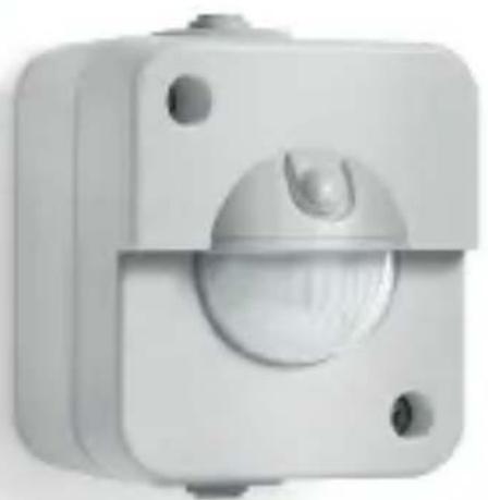
natural_image
Close-up of a white mechanical component with a central circular dial and mounting holes (no text or symbols visible)IR 180 UP easy
IR 180 AP easy

DE.....14 Textteil beachten!
GB .....24 Follow written instructions!
FR. . . . . .34 Se référer à la partie texte!
NL.....44 Neem tekstpassage in acht!
IT .....54 Seguire attentamente le istruzioni!
ES.....64 ¡Téngase en cuenta el texto!
PT.....73 Siga as instruções escritas!
SE.....82 laktta texten!
DK .....91 Følg den skriftlige vejledning!
FI .....100 Huomaa tekstiosio!
NO ....109 Se de skriftlige instruksene!
GR ....118 Τηρείτε γραπτές οδηγίες!
TR. . . . .127 Metin kısmını dikkate alın!
HU ....136 Szöveges részre figyelni!
CZ.....145 Dodržujte písemné pokyny!
SK.....154 Dodržiavajte písomné informácie!
PL.....163 Postępować zgodnie z instrukcją!
RO ....173 Respectați instrucțiunile următoare!
SI .....182 Upoštevajte besedilo!
HR ....191 Pridržavajte se uputa!
EE. . . . .200 Järgige tekstiosa!
LT .....209 Atsižvelgti j rašytines instrukcijas!
LV .....218 Pievērsiet uzmanību teksta dalai!
BG ....227 Соблюдать текстовую инструкцию!
CN ....236 Прочетете инструкциите!
RU . . .243 遵守文字说明要求!
3.1
natural_image
Technical line drawing of an electrical contactor assembly (no text or symbols)3.2
natural_image
Technical line drawing of three mechanical components with internal cutouts and mounting holes (no text or symbols)3.3
natural_image
Technical line drawing of a mechanical component with dimension标注 (no text or symbols)3.4
3.5
3.6
3.7
4.1
4.2
4.3
5.3
natural_image
Pure diagram of a pipe or channel with no text, numbers, or symbols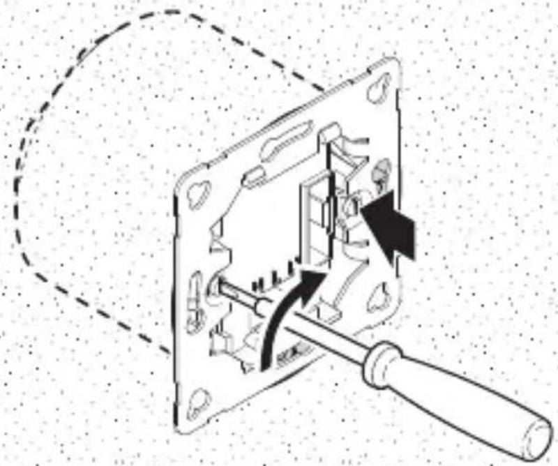
natural_image
Mechanical assembly diagram showing a disassembled component with arrows indicating motion or force (no text or symbols present)5.4
natural_image
Pure electrical circuit lines without any symbols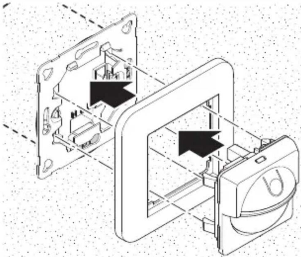
natural_image
Technical line drawing of a mechanical device with internal components and directional arrows (no text or symbols)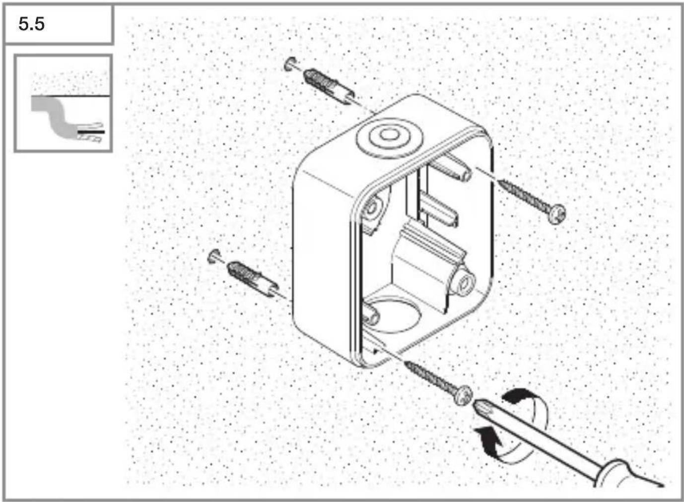
6.3
natural_image
Simple line drawing of a circular object with a central vertical line and horizontal bands, labeled 'H' at the bottom (no text or symbols beyond the label)DE
Please read carefully and keep in a safe place.
- Under copyright. Reproduction either in Whole or in part only With our consent.
-Subject to change in the interest of technical progress.
-All product dimensions in mm.
Symbols

Hazard Warning!
Reference to other information in the document.
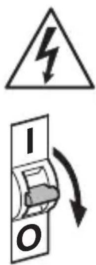
2. General safety precautions

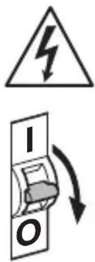
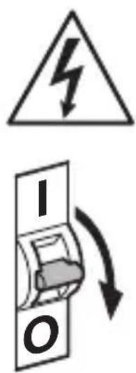
Disconnect the power supply before attempting any Work on the sensor switch.
- During installation, the electric power cable being connected must not be live. Therefore, switch off the power first and use a voltage tester to make sure the Wiring is off-circuit.
- Installing the sensor switch involves work on the mains voltage supply. This work must therefore be carried out professionally in accordance with national wiring regulations and electrical operating conditions (e.g.
DE: VDE 0100, AT: OVE-EN 1, CH: SEV 1000).
3. IR 180 UP easy / IR 180 AP easy
Proper use - IR 180 UP easy:
–Sensor switch for concealed installation in dry interior spaces.
Proper use - IR 180 AP easy:
- Sensor switch for surface installation in dry interior spaces and those exposed to moisture.
The sensor switches are equipped with a pyro sensor which detects the invisible heat emitted by moving objects (people, animals etc.). The heat detected in this way is converted electronically into a signal that switches a connected load ON (e.g. a light).
Heat is not detected through obstacles, such as walls or panes of glass, and will therefore not activate the light.
The sensor switch is designed for both 2 and 3-wire electrical systems.
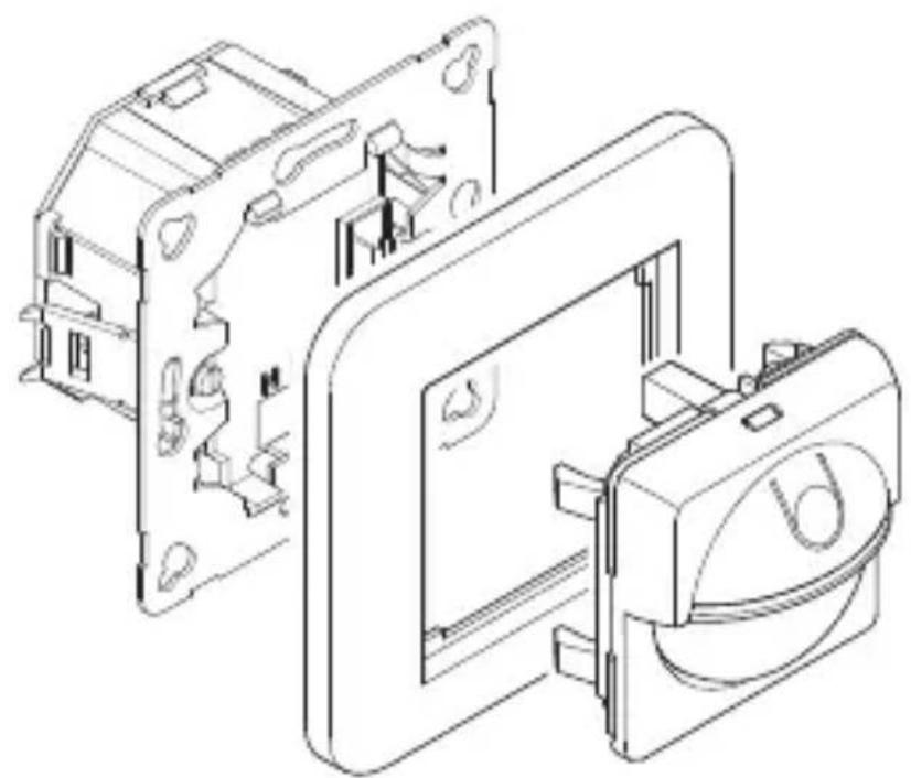
Package contents - IR 180 UP easy (Fig. 3.1) Package contents - IR 180 AP easy (Fig. 3.2)
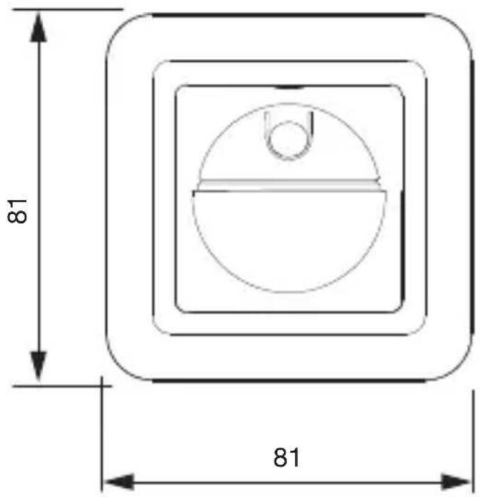
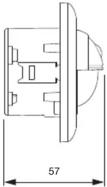
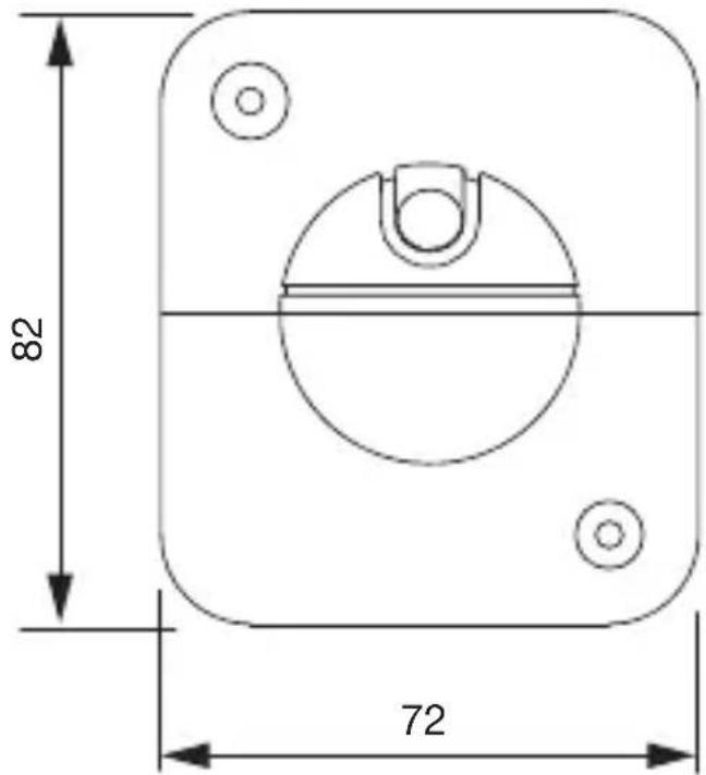
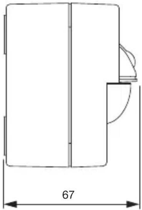
Product dimensions - IR 180 UP easy (Fig. 3.3) Product dimensions - IR 180 AP easy (Fig. 3.4)
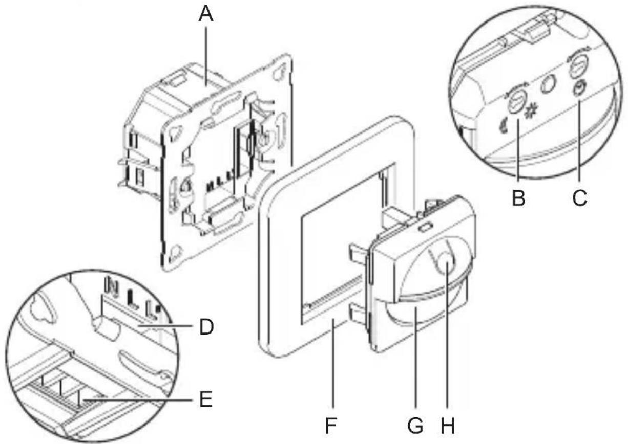
Product components - IR 180 UP easy (Fig. 3.5)
A Load module
B Twilight setting
C Time setting
D Connecting terminal screw shaft
E Connecting terminal cable duct
F Surround
G Sensor module
H Switch for light function
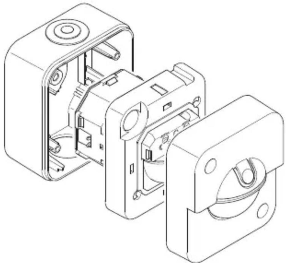
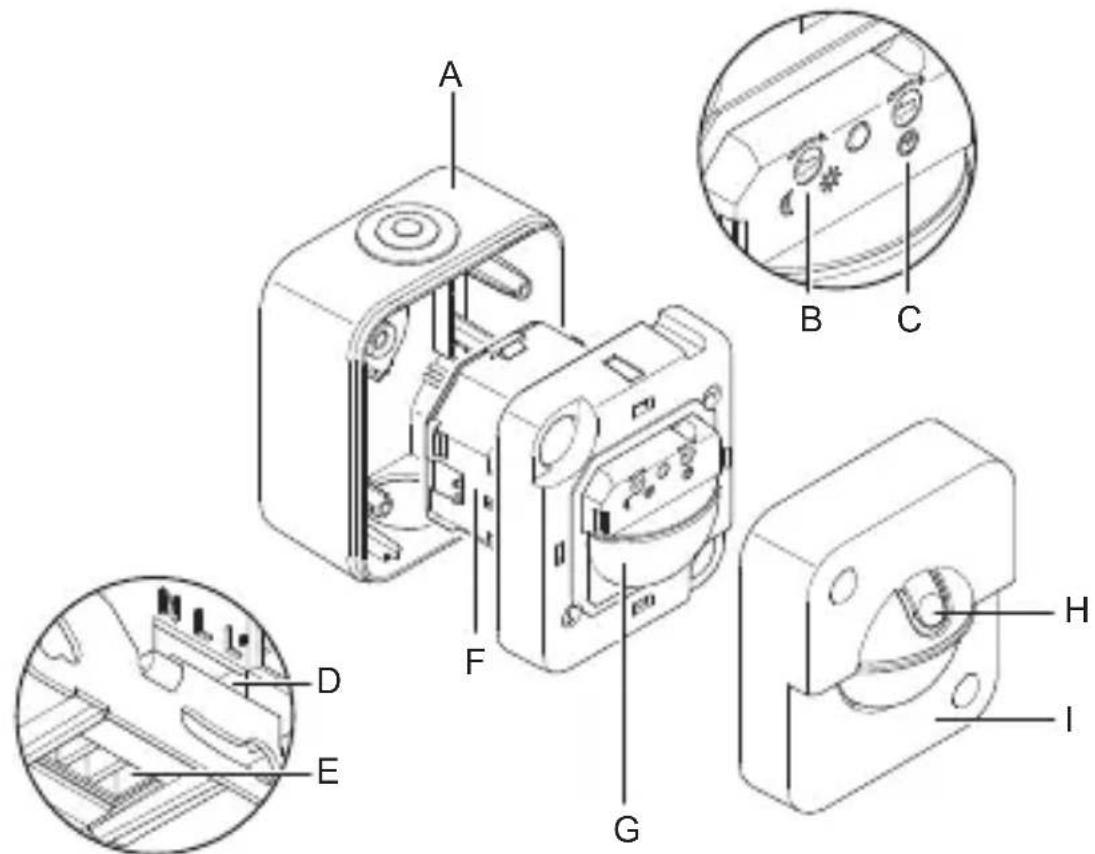
Product components - IR 180 AP easy (Fig. 3.6)
A Surface-mounting enclosure
B Twilight setting
C Time setting
D Connecting terminal screw shaft
E Connecting terminal cable duct
F Load module
G Sensor module
H Switch for light function
I Cover
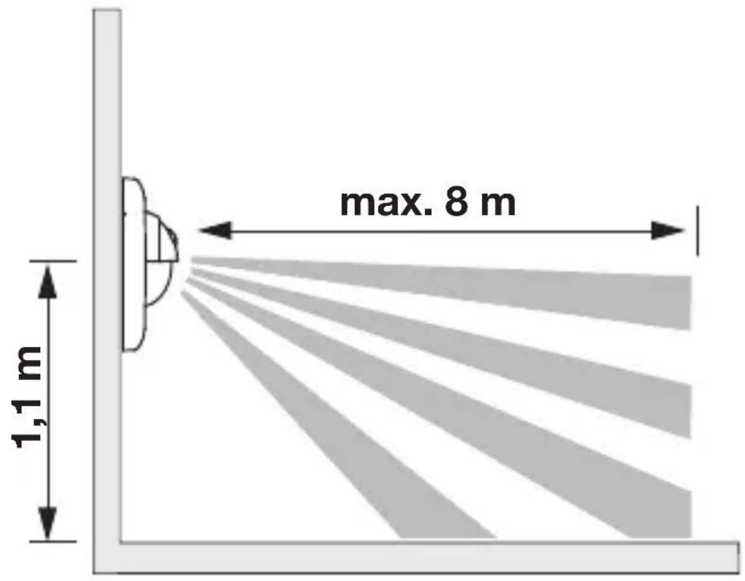
Detection zone (Fig. 3.7)
4. Electrical connection
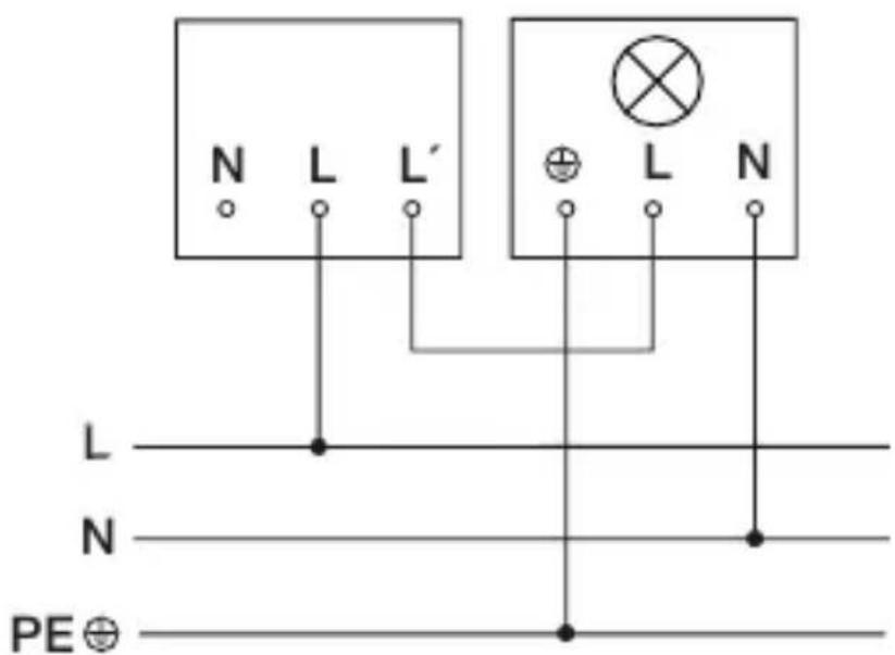
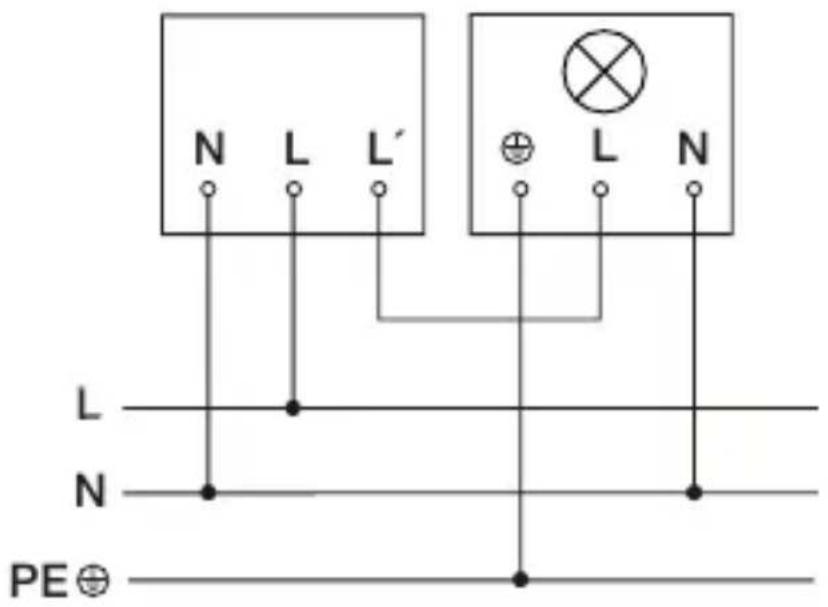
Connection wiring diagram: two-wire (Fig. 4.1)
Connection wiring diagram: three-wire (Fig. 4.2)
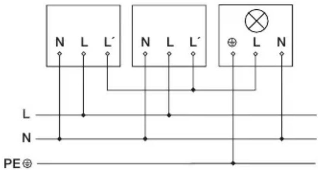
Connection wiring diagram: interconnecting several sensor switches (Fig. 4.3)
The supply lead is a 2 or 3-core cable:
L = phase conductor (usually black or brown)
N = neutral conductor (usually blue, optional)
L' = switched phase conductor (usually black, brown or grey)
If you are in any doubt, identify the conductors using a voltage tester; then disconnect from the power supply again. Connect phase conductor (L) and (L') to the terminal. Neutral conductor (N) can be connected to the terminal as an option. A protective-earth conductor is not required.
Important:
Mixing up the connections Will cause a short circuit in the product or your fuse box. In this case, you must identify the individual conductors once again and reconnect them.
L' detection provides the option of connecting as many as 5 sensors in parallel. This does not increase the maximum connectable load. The neutral conductor (N) must be connected at each sensor switch.
5. Mounting
- Check all components for damage.
- Do not use the product if it is damaged.
- Select an appropriate mounting location, taking the reach and motion detection into consideration.
Mounting procedure for concealed installation (UP)
- Switch OFF power supply (Fig. 4.1/4.2/4.3)
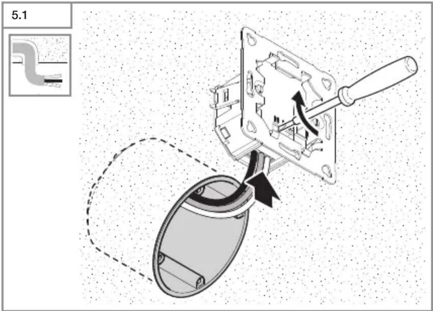
- Connect conductors to load module (Fig. 5.1)
-2-wire connection (Fig. 4.1)
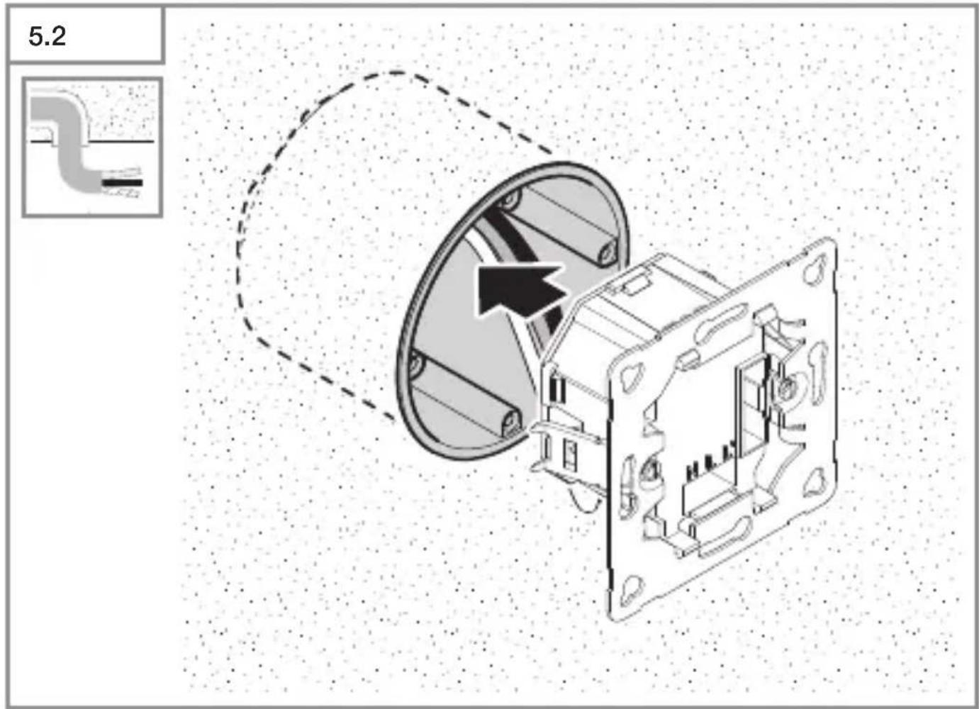
-3-wire connection (Fig. 4.2) - Push load module into the flush-mounting box (Fig. 5.2)
- Screw load module into place (Fig. 5.3)
- Fit surround and sensor module on load module (Fig. 5.4)
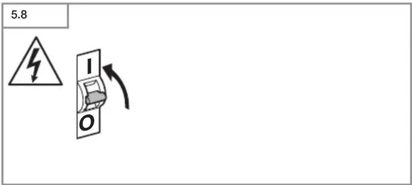
- Switch ON power supply (Fig. 5.8)
- Settings → "6. Function"
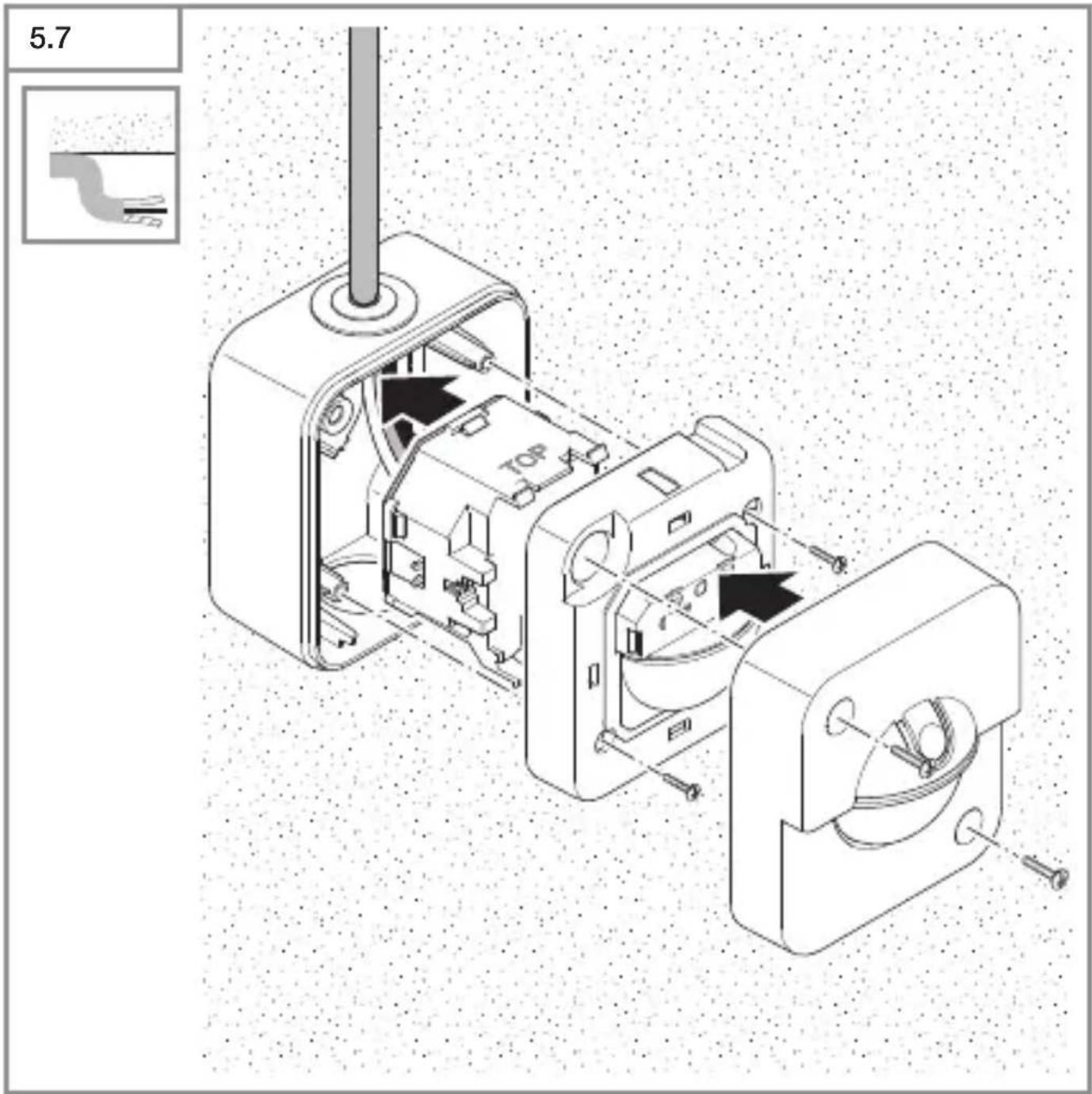
Mounting procedure for surface installation (AP)
- Switch OFF power supply (Fig. 4.1/4.2/4.3)
- Screw on surface-mounting enclosure (Fig. 5.5)
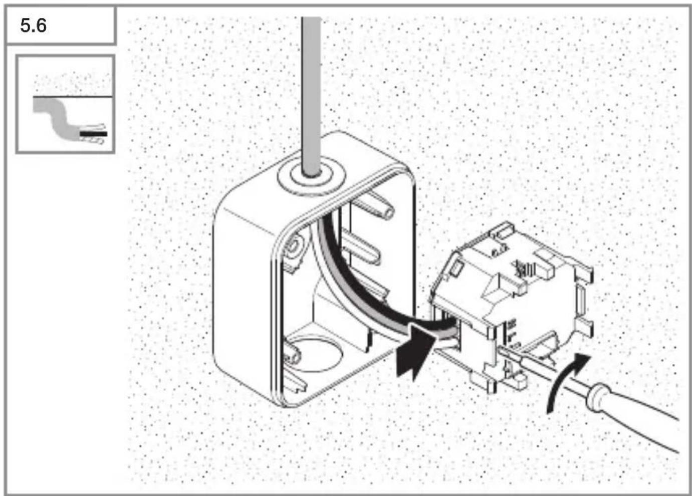
- Connect conductors to load module (Fig. 5.6)
-2-wire connection (Fig. 4.1)
-3-wire connection (Fig. 4.2)
• Fit load module, sensor module and cover (Fig. 5.7)
- Switch ON power supply (Fig. 5.8)
- Settings → "6. Function"
6. Function
Factory settings
Twilight setting: 1,000 Lux (daylight mode)
Time setting: 5 seconds
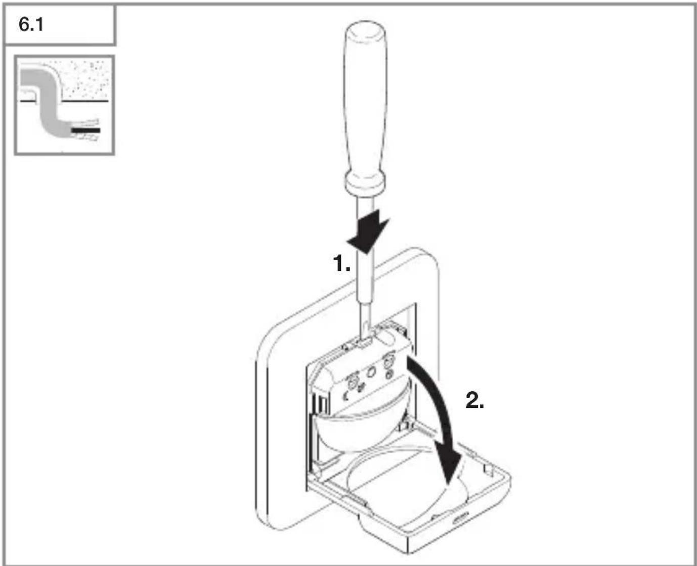
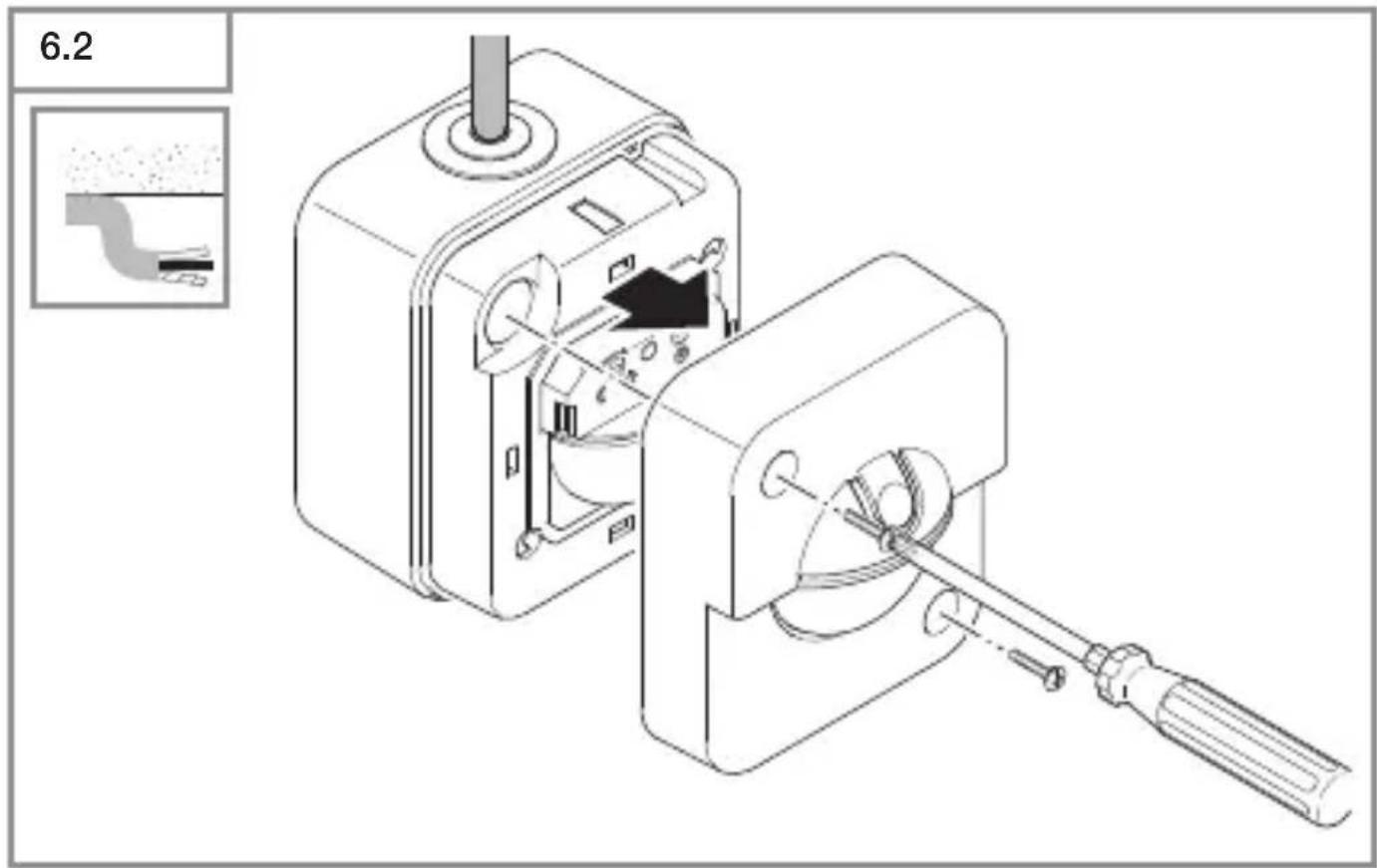
The sensor module must be opened to make the function settings.
- Press the screwdriver onto the tab and open the flap (concealed installation). (Fig. 6.1)
- Unscrew the cover (surface installation). (Fig. 6.2)
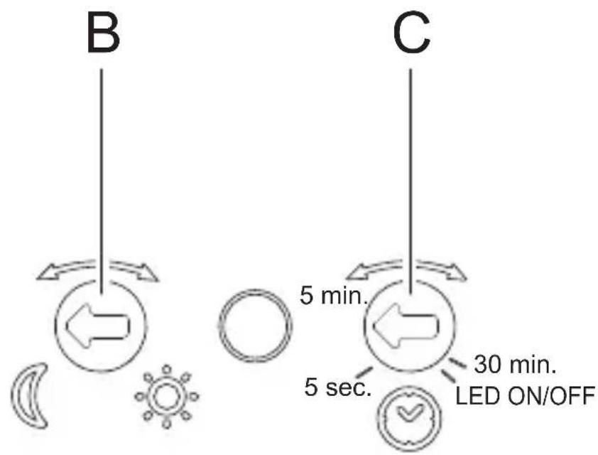
Twilight setting (Fig. 6.3/B)
The sensor switch response threshold can be set in increments from 2 lux to 1,000 lux.
Control dial set to 📋: daylight operation (independent of ambient light level) Control dial set to ⚙: twilight operation (2 lux)
The control dial must be turned to 📋 When adjusting the detection zone and performing the functional test in daylight.
Time setting (Fig. 6.3/C)
The time you Want the connected lamp to stay ON for can be set in increments from 5 seconds to a maximum of 30 minutes.
Control dial set to 5 s: shortest time (5 seconds)
Control dial set to 5 min: 5 minutes
Control dial set to 30 min: longest time (30 minutes)
The stay-ON time s restarted by any movement before this time elapses.
The shortest time setting is recommended When adjusting the detection zone and performing the functional test.
Note:
Every time the light switches OFF, it takes approximately 6 seconds for the sensor to start detecting movement again. Only after this time elapses can the sensor switch turn light ON again in response to motion.
LED ON / OFF
If you are irritated by the status LED, it can easily be switched OFF.
Briefly (1 second) set control dial to LED ON / OFF.
LED flashes once: LED is ON.
LED flashes twice: LED is OFF.
The control dial must then be adjusted to the chosen time setting. If this is not done, the time set is 2 minutes.
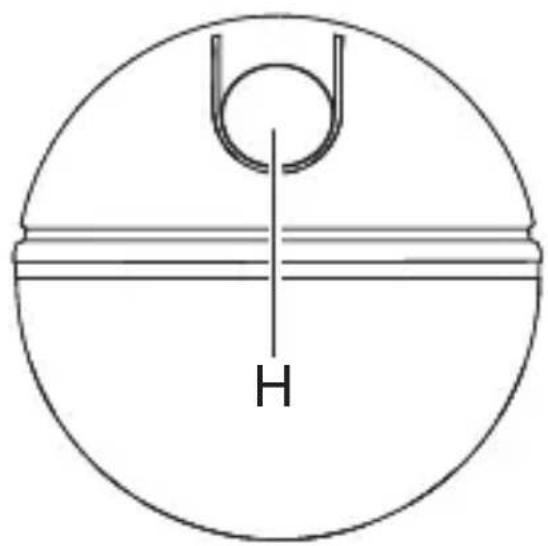
Switch for light function (Fig. 6.3/H)
Light ON status: press once
Light goes out. If no movement is being detected, the stay-ON time elapses and the sensor switch changes to normal sensor mode.
Light OFF status: press once
Light come ON even in sufficient ambient brightness. The light stays switched ON until the sensor switch turns it OFF because no movement is being detected or ambient brightness is sufficient.
Teach mode
Teach mode saves the current ambient light level below which you do not want the sensor switch to respond to movement from now on.
Pressing the button for 5 seconds programs in the light level. This takes place 5 seconds after releasing the button to prevent any shadow being cast over the brightness sensor. The LED flashes once to indicate that Teach mode has been selected. The connected lamp is switched OFF While the Teach cycle is in progress. The LED flashes once to confirm that the current ambient light level has been saved. The sensor switch then returns to sensor mode and operates With the new threshold. Teach mode can be repeated any number of times.
To quit Teach mode, turn the twilight setting control dial.
7. Maintenance and care
This product requires no maintenance.
The surface can be cleaned With a damp cloth (without detergents) if dirty.
8. Disposal
Electrical and electronic equipment, accessories and packaging must be recycled in an environmentally compatible manner.
Do not dispose of electrical and electronic equipment as domestic Waste.
EU countries only:
Under the current European Directive on Waste Electrical and Electronic Equipment and its implementation in national law, electrical and electronic equipment no longer suitable for use must be collected separately and recycled in an environmentally compatible manner.
9. Manufacturer's Warranty
Manufacturer's warranty of STEINEL GmbH, Dieselstrasse 80-84, DE-33442 Herzebrock-Clarholz, Germany
All STEINEL products meet the highest quality standards. For this reason, we, the manufacturer, are pleased to provide you, the consumer, with a warranty under the following terms and conditions:
The warranty covers the absence of deficiencies which are proven to be the result of a material defect or fault in manufacturing and which are reported to us immediately after detection and within the warranty period. The warranty shall apply to all STEINEL products sold and used in Germany - excluding STEINEL Professional products.
You can opt for warranty cover in the form of repair or replacement which will be provided free of charge (if applicable, in the form of a successor model of the same or higher quality) or in the form of a credit note. The warranty period for the STEINEL product you have purchased is 3 years (5 years for products from the XLED home range) in each case from the date on which the product was purchased.
We shall bear the shipping costs but not the transport risks involved in return shipment.
Statutory rights accruing from defects, gratuitousness
The warranty cover described here shall be applicable in addition to the statutory rights of warranty – including special consumer protection provisions – and shall not restrict or replace them. Exercising your statutory rights in the event of defects is gratuitous.
Exemptions from the warranty
All replaceable lamps are expressly excluded from this warranty. In addition to this, the warranty shall not cover:
- any wear resulting from use or any other natural wear of product parts or any deficiencies in the STEINEL product that are attributable to wear caused by use or other natural wear,
– any improper or non-intended use of the product or any failure to observe the operating instructions,
– any unauthorised additions, alterations or other modifications to the product or any deficiencies attributable to the use of accessory,
– supplementary or replacement parts which are not genuine STEINEL parts,
– any maintenance or care of products that is not carried out in accordance with the operating instructions,
– any attachment or installation that is not in accordance with STEINEL's installation instructions,
–any damage or loss occurring in transit.
Application of German law
The warranty shall be governed by German law excluding the United Nations Convention concerning the International Sale of Goods (CISG).
Making claims
If you wish to make a warranty claim, please send your product complete and carriage paid with the original receipt of purchase, which must show the date of purchase and product designation, either to your retailer or directly to us at STEINEL (UK) Ltd. – 25 Manasty Road, Axis Park, Orton Southgate, GB- Peterborough Cambs PE2 6UP United Kingdom. For this reason, we recommend that you keep your receipt of purchase in a safe place until the warranty period expires.
- Technical specifications
| IR 180 UP easy IR | 180 AP easy | |
| Dimensions (H × W × D) 81 × 81 × 57 mm | 82 × 72 × 67 mm | |
| Power supply 220 – 240 V, 50/60 Hz | ||
| Power consumption 25 mW | ||
| OutputIncandescent / halogen lamp loadLED / ECG load | 200 W160 W (50 units, c < 132 μF) | |
| Minimum connected load with N: 1 W | without N: 4 W | |
| Mounting height 1.1 m | ||
| Sensor system Passive infrared | ||
| Angle of coverage 180° with 90° angle of aperture | ||
| Reach Max. 8 m tangential | ||
| Twilight setting 2 – 1,000 lux | ||
| Time setting 5 s – 30 min | ||
| Temperature | 0 °C to +40 °C | |
| IP rating | IP20 | IP54 |
11. Troubleshooting
Malfunction Cause Remedy
| Sensor switch Without voltage | ■ Fuse has tripped, not switched ON■ Short circuit | ■ Activate, change fuse, turn ON mains switch, check Wiring With voltage tester■ Check connections |
| Sensor switch not switching ON | ■ Lamp faulty | ■ replace lamp |
| Sensor switch not switching ON | ■ Twilight setting in night-time mode during daytime operation■ Fuse has tripped | ■ Reset■ Activate, change fuse, check connection if necessary |
| Sensor switch not switching OFF | ■ Continued movement Within the detection zone■ Light is in detection zone and keeps switching ON as a result of temperature change■ Other sensor switch is connected in parallel and still active | ■ Check detection zone■ Check detection zone■ Wait for time setting of the other sensor switch to elapse |
| Sensor switch always switches ON / OFF | ■ Light being operated in the detection zone■ Animals moving in detection zone | ■ Check detection zone■ Check detection zone |
| LEDs glowing, flickering | ■ LEDs responding too sensitively | ■ Connect neutral conductor (N), change lamp |
12. LED flashing code for malfunction
| LED flashing code Cause | Remedy | |
| 1 flash every second | Operating malfunction Check | ck connections, change bulb, connect neutral conductor |
| 2 flashes every 5 seconds | Faulty power supply Check | connections, change bulb, connect neutral conductor |
| 3 flashes every 5 seconds | Overload, short circuit Check | ck connections, reduce output, reduce number of bulbs connected |
| 4 flashes every 5 seconds | Temperature too high Reduce | output |
| 5 flashes every 5 seconds | Temperature too low Check | place of use |
Once the malfunction has been remedied, the sensor switch can be restarted by pressing the button. For temperature faults only: the sensor automatically goes to normal operating mode as soon as the temperature has returned to normal.
FR
Mode Teach (apprentissage)
Led knippert 1 keer: led is ingeschakeld.
- Tekniska data
Monteringstrin for UP
Monteringstrin for AP
- Odvrnite poklopac (AP). (SI. 6.2)
Aja seadmine (Joon. 6.3/C)
natural_image
World map silhouette in grayscale, showing continents and oceans without any text or labelsContact
www.steinel.de/contact


- DE
- Please read carefully and keep in a safe place.
- Symbols
- General safety precautions
- IR 180 UP easy / IR 180 AP easy
- Proper use - IR 180 UP easy:
- Proper use - IR 180 AP easy:
- Electrical connection
- Important:
- Mounting
- Mounting procedure for concealed installation (UP)
- Mounting procedure for surface installation (AP)
- Function
- Factory settings
- Twilight setting (Fig. 6.3/B)
- Time setting (Fig. 6.3/C)
- Note:
- LED ON / OFF
- Switch for light function (Fig. 6.3/H)
- Light ON status: press once
- Light OFF status: press once
- Teach mode
- Maintenance and care
- Disposal
- EU countries only:
- Manufacturer's Warranty
- Statutory rights accruing from defects, gratuitousness
- Exemptions from the warranty
- Application of German law
- Making claims
- Troubleshooting
- LED flashing code for malfunction
- FR
- Mode Teach (apprentissage)
- Monteringstrin for UP
- Monteringstrin for AP
- Aja seadmine (Joon. 6.3/C)
- Contact
Brand : STEINEL
Model : IR 180 AP Easy
Category : Motion detector