5DB66251 - Basket BLAUPUNKT - Free user manual and instructions
Find the device manual for free 5DB66251 BLAUPUNKT in PDF.
| Brand | Blaupunkt |
| Model | 5DB66251 |
| Product type | Extractor hood |
| Installation version | External extraction (aspirating) or recirculation (filtering) |
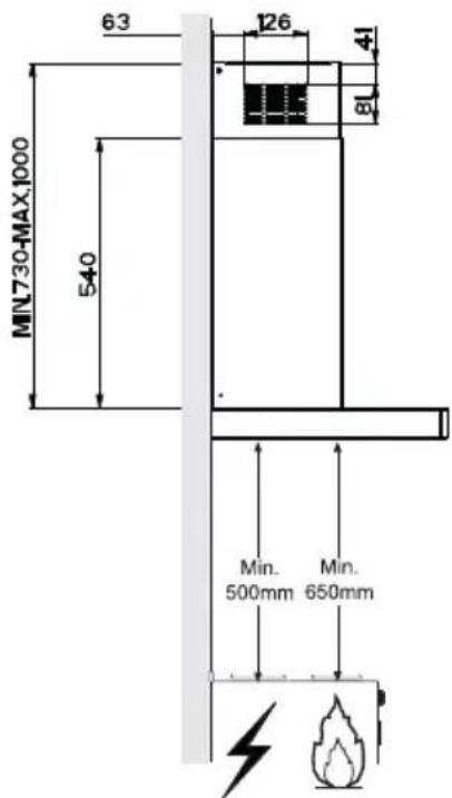
| Minimum distance to cooking surface | 650 mm |
| Number of motor speeds | 3 (V1 slow, V2 medium, V3 fast) |
| Lighting | Halogen lamp 28 W |
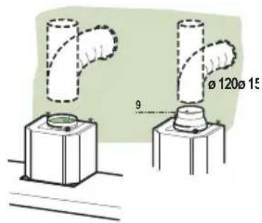
| Air outlet diameter | 150 or 120 mm (reducer supplied) |
| Grease filters | Self-supporting metal, dishwasher safe |
| Activated charcoal filter | Disposable, not washable, replace every 4 months |
| Telescopic chimney height | Adjustable from 598 to 1198 mm |
| Power supply | 230 V / 50 Hz (according to rating plate) |
| Insulation class | Class I (mandatory earthing) |
| Motor power | Not specified (estimated 200-300 W) |
| Noise level | Not specified |
| Main material | Stainless steel or lacquered (not specified) |
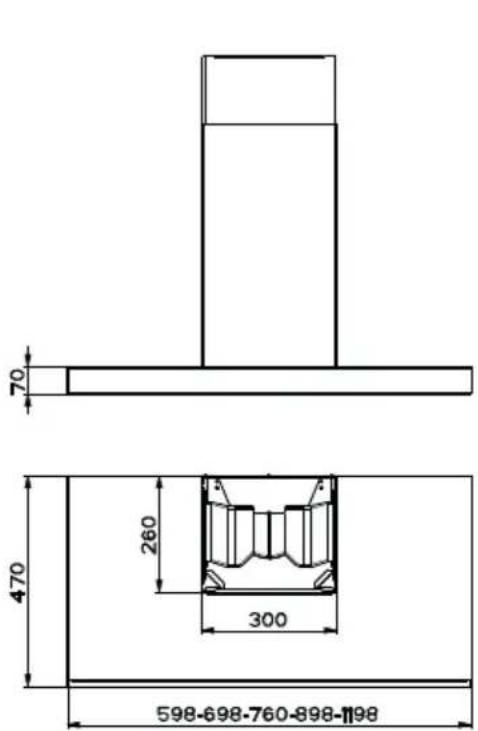
| Dimensions (W x D x H min.-max.) | 598-698-760-898-1198 mm (width) x 470 mm (depth) x 70-260 mm (hood height) + chimney |
| Weight | Approximately 12-15 kg (estimated) |
| Grease filter maintenance | Every 2 months, dishwasher wash |
| Charcoal filter replacement | Every 4 months (normal use) |
| Child safety | Not intended for children under 8 without supervision |
| Control | Push buttons (L, S, V1, V2, V3) |
| Manual available | French, German, English, Spanish, Italian, Dutch, Slovenian, Serbian, Swedish |
Frequently Asked Questions - 5DB66251 BLAUPUNKT
User questions about 5DB66251 BLAUPUNKT
0 question about this device. Answer the ones you know or ask your own.
Ask a new question about this device
Download the instructions for your Basket in PDF format for free! Find your manual 5DB66251 - BLAUPUNKT and take your electronic device back in hand. On this page are published all the documents necessary for the use of your device. 5DB66251 by BLAUPUNKT.
USER MANUAL 5DB66251 BLAUPUNKT
natural_image
Line drawing of a tall rectangular structure with a small window on top, mounted on a base (no text or symbols)RECOMMENDATIONS AND SUGGESTIONS 14
CHARACTERISTICS 17
INSTALLATION....18
USE 21
MAINTENANCE 22
INHALTSVERZEICHNIS
DE
CARACTERISTIQUES....37
INSTALLATION 38
UTILISATION 41
ENTRETIEN 42
INHOUDSOPGAVE
NL
ADVIEZEN EN SUGGESTIES 44
EIGENSCHAPPEN 47
INSTALLATIE 48
GEBRUIK 51
ONDERHOUD 52
INNEHÅLL
SE
REKOMMENDATIONER OCH TIPS 54
EGENSKAPER 57
INSTALLATION....58
ANVÄNDING....61
UNDERHÄLL 62
ÍNDICE
ES
natural_image
Illustration of a chemical experiment setup with a conical flask, smoke, and a control panel (no text or symbols)natural_image
Illustration of a greenhouse with a pot and smokestack, crossed by a green X (no text or symbols)natural_image
Simple line drawing of a T-shaped object with a height dimension labeled 70 (no text or symbols beyond the dimension)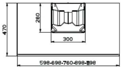
Componenti
natural_image
Isometric line drawing of a mechanical component with a cylindrical top and base (no text or symbols)natural_image
Diagram showing a mechanical component with an inset view of a tool interacting with a green arrow (no text or symbols present)Montaggio Camino
Camino superiore
natural_image
Hand pressing a green arrow on a device screen (no text or symbols visible)Filtro antiodore (Versione Filtrante)
SOSTITUZIONE FILTRO ANTIODORE AL CARBONE ATTIVO
natural_image
Illustration of a hand pressing a component on a green surface, with a green arrow indicating direction (no text or symbols)Illuminazione
natural_image
Line drawing of a hand holding a mechanical component, no text or symbols present| Lampada | Assorbimento (W) | Attacco Voltaggio (V) | Dimensione (mm) | Codice ILCOS | |
| [OK28] | 28 E14 220 | -240 104 x 35 | HSGSB/C/UB-28-220/240-E14 | ||
| [OK427] | 28 | E14 | 230 | 85x25 HDG-28-230-E14-25 | |
| [43971] | 20 G4 12 33 x 9 HSG/C/UB-20-12-G4 | ||||
 | 35 | GU10 | 230 | 51 x 50,7 | HAGS-35-230-GU10-51/40 |
| 50 | GU10 | 230 | 51 x 50,7 | HAGS-35-230-GU10-51/20 | |
 | 20 | GU4 | 12 | 40 x 35 | HRGS-20-12-GU4-35/30 |
| 20 | GU5.3 | 12 | 46 x 51 | HRGS-20-12-GU5.3-50/10 | |
| ### | 16 | G13 | 95 | 720 x 26 | FD-16/40/1B-E-G13-26/720 |
| 18 | G13 | 57 | 589,8 x 26 | FD-18/40/1B-E-G13-26/600 | |
| ### | 9 | G23 | 60 (lampada)220-240 (starter) | 167 x 28 | FSD-9/27/1B-I-G23 |
| 11 | G23 | 91 (lampada)220-240 (starter) | 235,8 x 28 | FSD-11/40/1B-I-G23 | |
The Instructions for Use apply to several versions of this appliance.
Accordingly, you may find descriptions of individual features that do not apply to your specific appliance.
INSTALLATION
- The manufacturer will not be held liable for any damages resulting from incorrect or improper installation.
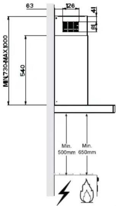
- The minimum safety distance between the cooker top and the extractor hood is 650 mm (some models can be installed at a lower height, please refer to the paragraphs on working dimensions and installation).
- Check that the mains voltage corresponds to that indicated on the rating plate fixed to the inside of the hood.
- For Class I appliances, check that the domestic power supply guarantees adequate earthing.
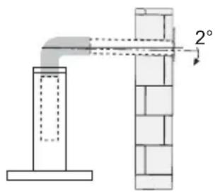
Connect the extractor to the exhaust flue through a pipe of minimum diameter 120 mm. The route of the flue must be as short as possible.
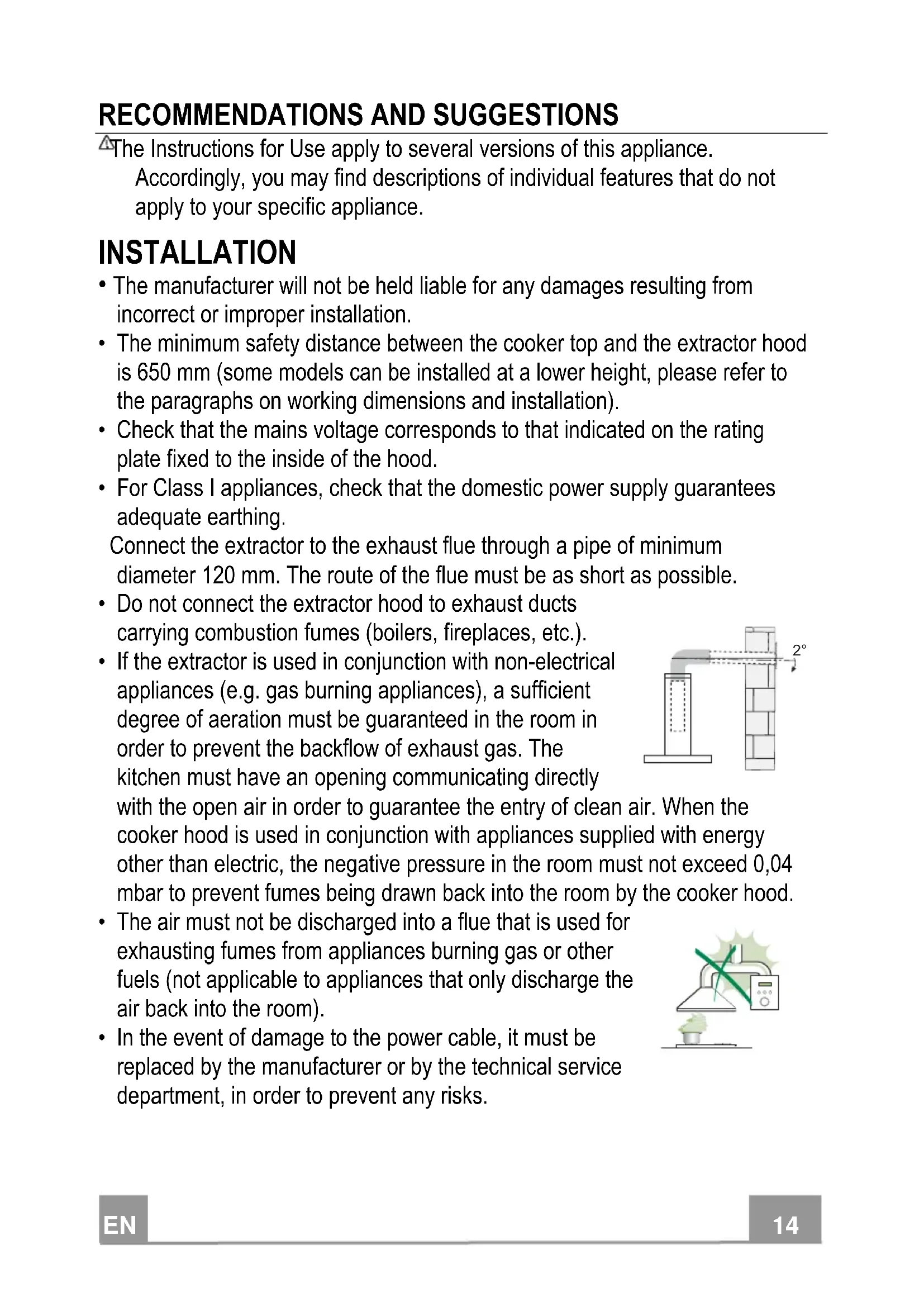
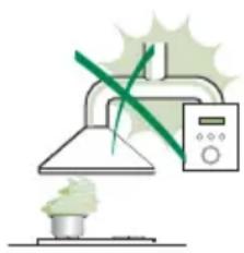
- Do not connect the extractor hood to exhaust ducts carrying combustion fumes (boilers, fireplaces, etc.).
- If the extractor is used in conjunction with non-electrical appliances (e.g. gas burning appliances), a sufficient degree of aeration must be guaranteed in the room in order to prevent the backflow of exhaust gas. The kitchen must have an opening communicating directly
with the open air in order to guarantee the entry of clean air. When the cooker hood is used in conjunction with appliances supplied with energy other than electric, the negative pressure in the room must not exceed 0,04 mbar to prevent fumes being drawn back into the room by the cooker hood.
- The air must not be discharged into a flue that is used for exhausting fumes from appliances burning gas or other fuels (not applicable to appliances that only discharge the air back into the room).
- In the event of damage to the power cable, it must be replaced by the manufacturer or by the technical service department, in order to prevent any risks.
natural_image
Illustration of a chemical experiment setup with a conical flask, thermometer, and smokestack (no text or symbols)- If the instructions for installation for the gas hob specify a greater distance specified above, this has to be taken into account. Regulations concerning the discharge of air have to be fulfilled.
- Use only screws and small parts in support of the hood.
Warning: Failure to install the screws or fixing device in accordance with these instructions may result in electrical hazards. - Connect the hood to the mains through a two-pole switch having a contact gap of at least 3 mm.
USE
- The extractor hood has been designed exclusively for domestic use to eliminate kitchen smells.
- Never use the hood for purposes other than for which it has been designed.
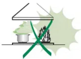
- Never leave high naked flames under the hood when it is in operation.
- Adjust the flame intensity to direct it onto the bottom of the pan only, making sure that it does not engulf the sides.
- Deep fat fryers must be continuously monitored during use: overheated oil can burst into flames.
- Do not flambè under the range hood; risk of fire.
- This appliance can be used by children aged from 8 years and above and persons with reduced physical, sensory or mental capabilities or lack of
natural_image
Illustration of a greenhouse with a pot and smokestack, crossed by a green X-shaped line (no text or symbols)experience and knowledge if they have been given supervision or instruction concerning use of the appliance in a safe way and understand the hazards involved. Children shall not play with the appliance. Cleaning and user maintenance shall not be made by children without supervision.
- This appliance is not intended for use by persons (including children) with reduced physical, sensory or mental capabilities, or lack of experience and knowledge, unless they have been given supervision or instruction concerning use of the appliance by a person responsible for their safety.
- “CAUTION: Accessible parts may become hot when used with cooking appliances.”
MAINTENANCE
- Switch off or unplug the appliance from the mains supply before carrying out any maintenance work.
- Clean and/or replace the Filters after the specified time period (Fire hazard).
- The Grease filters must be cleaned every 2 months of operation, or more frequently for particularly heavy usage, and can be washed in a dishwasher.
- The Activated charcoal filter is not washable and cannot be regenerated, and must be replaced approximately every 4 months of operation, or more frequently for particularly heavy usage.
- "Failure to carry out cleaning as indicated will result in a fire hazard".
- Clean the hood using a damp cloth and a neutral liquid detergent.
The symbol on the product or on its packaging indicates that this product may not be treated as household waste. Instead it shall be handed over to the applicable collection point for the recycling of electrical and electronic equipment. By ensuring this product is disposed of correctly, you will help prevent potential negative consequences for the environment and human health, which could otherwise be caused by inappropriate waste handling of this product. For more detailed information about recycling of this product, please contact your local city office, your household waste disposal service or the shop where you purchased the product.
Dimensions
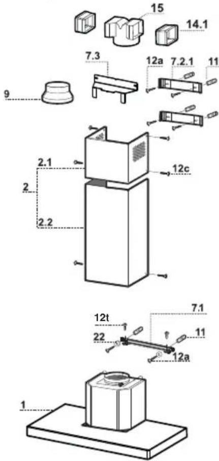
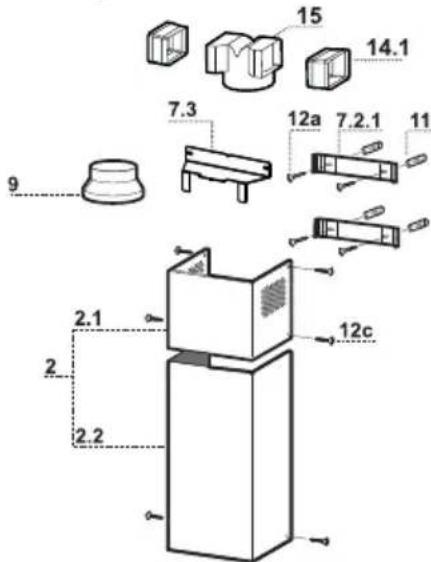
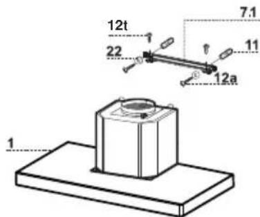
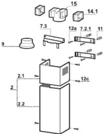
Components
| Ref. | Q.ty | Product Components | |
| 1 | 1 | Hood Body, complete with: Controls, Light, Blower, Filters | |
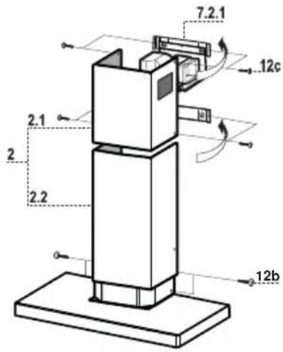
| 2 | 1 | Telescopic Chimney comprising: | |
| 2.1 | 1 | Upper Section | |
| 2.2 | 1 | Lower Section | |
| 9 | 1 | Reducer Flange ø 150-120 mm | |
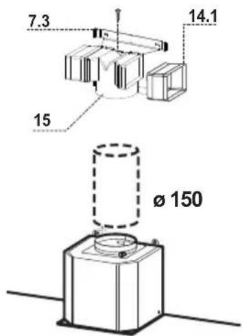
| 14.1 | 2 | Air Outlet Connection Extension | |
| 15 | 1 | Air Outlet Connection | |
| Ref. | Q.ty | Installation Components | |
| 7.1 | 1 | Hood Body Fixing Brackets | |
| 7.2.1 | 2 | Upper Chimney Section Fixing Brackets | |
| 7.3 | 1 | Air Outlet Connection | |
| 11 | 6 | Wall Plugs | |
| 12a | 6 | Screws 4,2 x 44,4 | |
| 12c | 6 | Screws 2,9 x 6,5 | |
| 12e | 2 | Screws 2,9 x 9,5 | |
| 12t | 2 Screws 3,5 x 9,5 | ||
| 22 | 2 Washers | ||
| Q.ty | Documentation | ||
| 1 | Instruction Manual | ||
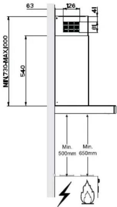
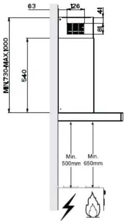
Wall drilling and bracket fixing
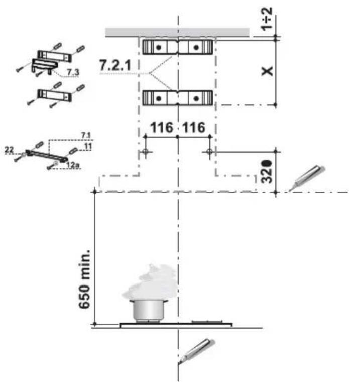
Wall marking:
- Draw a vertical line on the supporting wall up to the ceiling, or as high as practical, at the centre of the area in which the hood will be installed.
- Draw a horizontal line at 650 mm above the hob.
- Place bracket 7.2.1 on the wall as shown about 1-2 mm from the ceiling or upper limit aligning the centre (notch) with the vertical reference line.
• Mark the wall at the centres of the holes in the bracket. - Place bracket 7.2.1 on the wall as shown at X mm below the first bracket (X = height of the upper chimney section supplied), aligning the centre (notch) with the vertical line.
• Mark the wall at the centres of the holes in the bracket. - Mark a reference point as indicated at 116 mm from the vertical reference line and 320 mm above the horizontal reference line.
- Repeat this operation on the other side.
- Drill 8 mm holes at all the centre points marked.
- Insert the wall plugs 11 in the holes.
- Fix the lower bracket 7.2.1 using the 12a screws (4,2 x 44,4) supplied.
- Fix the upper bracket 7.2.1 and the air outlet connection support 7.3 together using the 2 screws 12a (4,2 x 44,4) supplied.
- Fix the Hood Body Fixing Brackets 7.1 using the 2 screws 12a (4,2 x 44,4) and Washers 22 supplied, checking levelling.
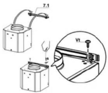
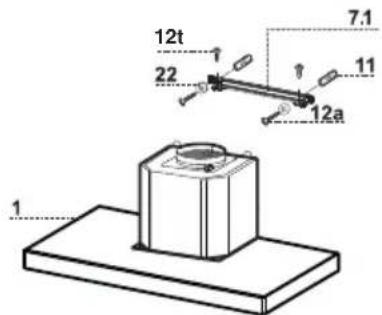
Installation with Bracket
- Hook the hood body onto the bracket 7.1 installed.
• Fix definitively the Hood body onto the bracket by 2 Screws 12t.
Connections
DUCTED VERSION AIR EXHAUST SYSTEM
When installing the ducted version, connect the hood to the chimney using either a flexible or rigid pipe 150 or 120 mm, the choice of which is left to the installer.
- To install a ø 120 mm air exhaust connection, insert the reducer flange 9 on the hood body outlet.
- Fix the pipe in position using sufficient pipe clamps (not supplied).
- Remove possible charcoal filters.
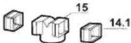
RECIRCULATION VERSION AIR OUTLET
- Insert the connection extension pieces laterally 14.1 in connection 15.
- Insert the Connector 15 into the Support bracket 7.3 and fix it with a screw.
- Make sure that the outlet of the extension pieces 14.1 is horizontally and vertically aligned with the chimney outlets.
- Connect the air outlet connection 15 to the hood body outlet using either a flexible or rigid pipe ∅ 150 mm, the choice of which is left to the installer.
- Ensure that the activated charcoal filters have been inserted.
ELECTRICAL CONNECTION
- Connect the hood to the mains through a two-pole switch having a contact gap of at least 3 mm.
- Remove the grease filters (see paragraph Maintenance) being sure that the connector of the feeding cable is correctly inserted in the socket placed on the side of the fan.
natural_image
Diagram showing a mechanical component with an inset view of a tool interacting with a green arrow (no text or symbols present)Flue assembly
Upper exhaust flue
- Slightly widen the two sides of the upper flue and hook them behind the brackets 7.2.1, making sure that they are well seated.
- Secure the sides to the brackets by using the 4 screws 12c (2,9 x 9,5) supplied.
- Make sure that the outlet of the extensions pieces is aligned with the chimney outlets.
Lower exhaust flue
- Slightly widen the two sides of the flue and hook them between the upper flue and the wall, making sure that they are well seated.
- Fix the lower part laterally to the hood body by using the 2 screws 12c (2,9 x 9,5) supplied.
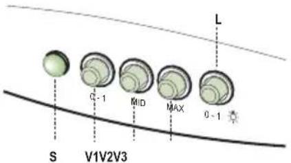
L Light Switches the lighting system on and off.
| S | Led | Motor running led. |
| V1 | Motor Switches the extractor motor on and off at low speed. Used to provide a continuous and silent air change in the presence of light cooking vapours. | |
| V2 | Speed | Medium speed, suitable for most operating conditions given the optimum treated air flow/noise level ratio. |
| V3 | Speed | Maximum speed, used for eliminating the highest cooking vapour emission, including long periods. |
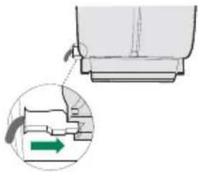
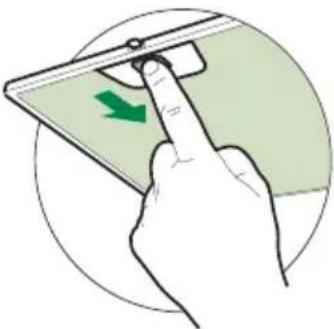
Grease filters
CLEANING METAL SELF- SUPPORTING GREASE FILTERS
- The filters must be cleaned every 2 months of operation, or more frequently for particularly heavy usage, and can be washed in a dishwasher.
- Remove the filters one at a time by pushing them towards the back of the group and pulling down at the same time.
- Wash the filters, taking care not to bend them. Allow them to dry before refitting.
- When refitting the filters, make sure that the handle is visible on the outside.
natural_image
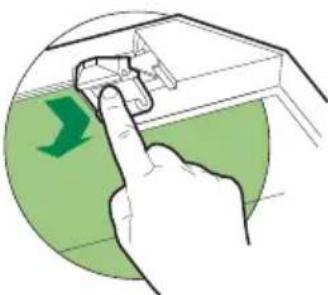
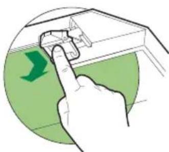
Hand pressing a green arrow on a device screen (no text or symbols visible)Activated charcoal filter (Recirculation version)
REPLACING THE ACTIVATED CHARCOAL FILTER
- The filter is not washable and cannot be regenerated, and must be replaced approximately every 4 months of operation, or more frequently for particularly heavy usage.
- Remove the metal grease filters.
- Remove the saturated activated carbon filter by releasing the fixing hooks.
• Fit the new filter by hooking it into its seating. - Refit the metal grease filters.
natural_image
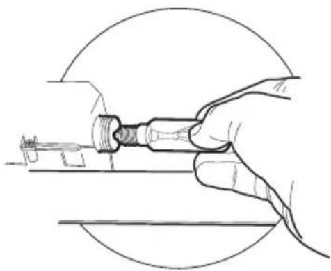
Illustration of a hand pressing a component on a green surface, with a green arrow indicating direction (no text or symbols)Lighting
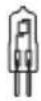
LIGHT REPLACEMENT
28 W halogen light.
- Remove the metal grease filters.
- Unscrew the bulbs and replace them with new ones having the same characteristics.
- Replace the metal grease filters.
natural_image
Line drawing of a hand holding a tool, no text or symbols present| Lamp Power (W) Socket Voltage (V) Dimension (mm) ILCO$ Code | |||||
| (Z42Y) | 28 E14 220 - 240 104 x | 35 | HSGSB/C/UB-28-220/240-E14 | ||
| (454T) | 28 | E14 | 230 | 85x25 HDG-28-230-E14-25 | |
| (HY88) | 20 | G4 | 12 | 33 x 9 | |
 | 35 | GU10 | 230 | 51 x 50,7 | HAGS-35-230-GU10-51/40 |
| 50 | GU10 | 230 | 51 x 50,7 | HAGS-35-230-GU10-51/20 | |
 | 20 | GU4 | 12 | 40 x 35 | HRGS-20-12-GU4-35/30 |
| 20 | GU5.3 | 12 | 46 x 51 | HRGS-20-12-GU5.3-50/10 | |
| (m/s) | 16 | G13 | 95 | 720 x 26 | FD-16/40/1B-E-G13-26/720 |
| 18 | G13 | 57 | 589,8 x 26 | FD-18/40/1B-E-G13-26/600 | |
| (kw) | 9 | G23 | 60 (lamp)220-240 (starter) | 167 x 28 | FSD-9/27/1B-I-G23 |
| 11 | G23 | 91 (lamp)220-240 (starter) | 235,8 x 28 | FSD-11/40/1B-I-G23 | |
natural_image
Illustration of a chemical experiment setup with a conical flask, thermometer, and smokestack (no text or symbols)natural_image
Technical diagram showing a pipe joint with a 2° angle indicator (no text or symbols present)natural_image
Illustration of a greenhouse with a stove and a crossed green ribbon, no text or symbols presentnatural_image
Simple line drawing of a T-shaped object with a height dimension labeled 70 (no text or symbols beyond the dimension)
Komponenten

natural_image
Diagram showing a mechanical component with an inset view of a tool interacting with a green arrow (no text or symbols present)Kaminmontage
Oberer Kaminteil
natural_image
Hand holding a tablet device with a green arrow indicating left touch (no text or symbols)Geruchsfilter (Umluftversion)
natural_image
Illustration of a hand pressing a component on a green surface, with a green arrow indicating direction (no text or symbols)Beleuchtung
AUSWECHSELN DER LAMPEN
Halogenlampe 28 W
natural_image
Line drawing of a hand holding a tool, no text or symbols present| Lampe Leistung (W) Fassung Spannung (V) | Größe (mm) ILCOS-Code | ||||
| (D580) | 28 E14 220 | -240 104 x 35 | HSGSB/C/UB-28-220/240-E14 | ||
| (7Y22) | 28 | E14 | 230 | 85x25 | HDG-28-230-E14-25 |
| (88X7) | 20 G4 12 33 x 9 | HSG/C/UB-20-12-G4 | |||
| (Z7G3) | 35 | GU10 | 230 | 51 x 50,7 | HAGS-35-230-GU10-51/40 |
| 50 | GU10 | 230 | 51 x 50,7 | HAGS-35-230-GU10-51/20 | |
| (X436) | 20 | GU4 | 12 | 40 x 35 | HRGS-20-12-GU4-35/30 |
| 20 GU5.3 | 12 | 46 x 51 | HRGS-20-12-GU5.3-50/10 | ||
| 16 | G13 | 95 | 720 x 26 | FD-16/40/1B-E-G13-26/720 | |
| 18 | G13 | 57 | 589,8 x 26 | FD-18/40/1B-E-G13-26/600 | |
| 9 | G23 | 60 (Lampe)220-240 (Starter) | 167 x 28 | FSD-9/27/1B-I-G23 | |
| 11 | G23 | 91 (Lampe)220-240 (Starter) | 235,8 x 28 | FSD-11/40/1B-I-G23 | |
natural_image
Illustration of a chemical experiment setup with a conical flask, thermometer, and test tube (no text or symbols)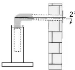
natural_image
Diagram of a pipe connection with a 2° angle indicator, showing structural components without any text or symbols.natural_image
Illustration of a greenhouse with a container and two plants, crossed by a green X (no text or symbols)natural_image
Diagram showing a mechanical component with an inset view of a tool interacting with a green arrow (no text or symbols present)Montage Cheminée
Cheminée supérieure
natural_image
Hand holding a tablet device with a green arrow indicating left touch (no text or symbols)Filtre anti-odeur (Version filtrante)
REPLACEMENT FILTRE AU CHARBON ACTIF
natural_image
Illustration of a hand pressing a component on a green surface, with a green arrow indicating direction (no text or symbols)Eclairage
REPLACEMENT LAMPES
natural_image
Line drawing of a hand holding a tool, no text or symbols present| Ampoule | Absorption (W) | Culot Voltage | (V) Dimensions (mm) | Code ILCOS | |
| [WAKC] | 28 E14 220 | -240 104 x 35 | HSGSB/C/UB-28-220/240-E14 | ||
| [80V0] | 28 | E14 | 230 | 85x25 | HDG-28-230-E14-25 |
| [KRT2] | 20 | G4 | 12 | 33 | x 9 |
 | 35 | GU10 | 230 | 51 x 50,7 | HAGS-35-230-GU10-51/40 |
| 50 | GU10 | 230 | 51 x 50,7 | HAGS-35-230-GU10-51/20 | |
 | 20 | GU4 | 12 | 40 x 35 | HRGS-20-12-GU4-35/30 |
| 20 | GU5.3 | 12 | 46 x 51 | HRGS-20-12-GU5.3-50/10 | |
| [IMAGE] | 16 | G13 | 95 | 720 x 26 | FD-16/40/1B-E-G13-26/720 |
| 18 | G13 | 57 | 589,8 x 26 | FD-18/40/1B-E-G13-26/600 | |
| [IMAGE] | 9 | G23 | 60 (ampoule)220-240 (starter) | 167 x 28 | FSD-9/27/1B-I-G23 |
| 11 | G23 | 91 (ampoule)220-240 (starter) | 235,8 x 28 FSD-1 | 1/40/1B-I-G23 |
HSG/C/UB-20-
natural_image
Illustration of a chemical experiment setup with a conical flask, thermometer, and smokestack (no text or symbols)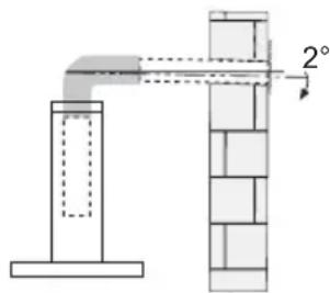
natural_image
Illustration of a cooking setup with a pot and steam rising, crossed by a green ribbon (no text or symbols)natural_image
Simple line drawing of a T-shaped object with a height dimension labeled 70 (no text or symbols beyond the dimension)
Onderdelen
Ref. Aantal Installatieonderdelen
| 7.1 | 1 | Bevestigingsbeugel | afzuigkap |
natural_image
Isometric line drawing of a mechanical component with a cylindrical top and base (no text or symbols)natural_image
Diagram showing a mechanical component with an inset view of a tool interacting with a green arrow (no text or symbols present)natural_image
Hand inserting a green arrow on a device screen, enclosed in a circular frame (no text or symbols)Geurfilter (filterversie)
VERVANGING FILTER MET ACTIEVE KOOLSTOF
natural_image
Illustration of a hand pressing a component on a green surface, with a green arrow indicating direction (no text or symbols)Verlichting
VERVANGING VAN DE LAMPEN
natural_image
Line drawing of a hand holding a tool, no text or symbols present| Lamp Stroomopname (W) Aansluiting Voltage (V) Afmeting (mm) ILCOS-code | |||||
| [4HAS] | 28 E14 220 | -240 104 x 35 | HSGSB/C/UB-28-220/240-E14 | ||
| [AZTA] | 28 | E14 | 230 | 85x25 | HDG-28-230-E14-25 |
 | 20 G4 12 33 x 9 | HSG/C/UB-20-12-G4 | |||
 | 35 | GU10 | 230 | 51 x 50,7 | HAGS-35-230-GU10-51/40 |
| 50 | GU10 | 230 | 51 x 50,7 | HAGS-35-230-GU10-51/20 | |
 | 20 | GU4 12 | 40 x 35 | HRGS-20-12-GU4-35/30 | |
| 20 | GU5.3 | 12 | 46 x 51 | HRGS-20-12-GU5.3-50/10 | |
| === | 16 | G13 | 95 | 720 x 26 | FD-16/40/1B-E-G13-26/720 |
| 18 | G13 | 57 | 589,8 x 26 | FD-18/40/1B-E-G13-26/600 | |
| ### | 9 | G23 | 60 (lamp)220-240 (starter) | 167 x 28 | FSD-9/27/1B-I-G23 |
| 11 | G23 | 91 (lamp)220-240 (starter) | 235,8 x 28 | FSD-11/40/1B-I-G23 | |
REKOMMENDATIONER OCH TIPS

natural_image
Illustration of a chemical experiment setup with a conical flask, thermometer, and smokestack (no text or symbols)natural_image
Illustration of a greenhouse with a pot and two plants, crossed by a green X (no text or symbols)natural_image
Simple line drawing of a T-shaped object with a height dimension labeled 70 (no text or symbols beyond the dimension)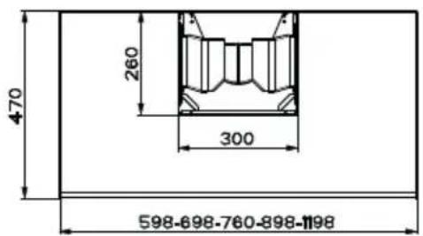
Komponenter
Ref. Antal Produktkomponenter
natural_image
Isometric diagram of a mechanical component with a cylindrical top and base, labeled with number 1 (no text or symbols on the object itself)natural_image
Diagram showing a mechanical component with an inset view of a green arrow indicating direction (no text or symbols present)MONTERING AV SKORSTEN
natural_image
Hand pressing a green arrow on a device screen (no text or symbols visible)Kolfilter
natural_image
Hand pressing a component on a green surface, no text or symbols visibleBelysning
BYTE AV LAMPA
Halogenlampor, 28W
natural_image
Line drawing of a hand holding a tool, no text or symbols present| Lampa Førbrukning (W) Sockel | Spänning (V) | Mått (mm) ILCOS | art.nr | ||
| (ZWC0) | 28 E14 220- | 240 104 x 35 | HSGSB/C/UB-28-220/240-E14 | ||
| (ZDSX) | 28 | E14 | 230 | 85x25 | HDG-28-230-E14-25 |
| (H66Z) | 20 G4 12 33 x 9 HSG/C/UB-20-12-G4 | ||||
 | 35 | GU10 230 | 51 | x 50,7 | |
| 50 | GU10 230 | 51 | x 50,7 | ||
| 20 | GU4 | 12 | 40 x 35 | HRGS-20-12-GU4-35/30 |
| 20 GU5.3 | 12 | 46 x 51 HRGS-20-12-GU5.3-50/10 | |||
| (n=0) | 16 | G13 | 95 | 720 x 26 | FD-16/40/1B-E-G13-26/720 |
| 18 | G13 | 57 | 589,8 x 26 | FD-18/40/1B-E-G13-26/600 | |
| (n=0) | 9 | G23 | 60 (lampa)220-240 (starter) | 167 x 28 | FSD-9/27/1B-I-G23 |
| 11 | G23 | 91 (lampa)220-240 (starter) | 235,8 x 28 | FSD-11/40/1B-I-G23 | |

natural_image
Illustration of a kitchen with a smokestack emitting vapor, no text or symbols present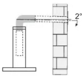
natural_image
Illustration of a greenhouse with a pot and smokestack, crossed by green ribbon (no text or symbols)natural_image
Simple line drawing of a T-shaped object with a height dimension labeled 70 (no text or symbols beyond the dimension)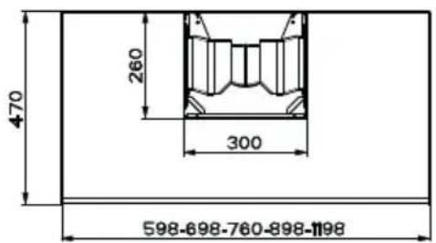
Componentes
natural_image
Diagram showing a mechanical component with an inset view of a tool interacting with a green arrow (no text or symbols present)natural_image
Hand pressing a green arrow on a device screen (no text or symbols visible)natural_image
Illustration of a hand pressing a component on a green surface, with a green arrow indicating direction (no text or symbols)natural_image
Line drawing of a hand holding a tool, no text or symbols present| Lámpara | Consumo energía (W) | deCasquillo | Voltaje (V) Dimensión (mm) | Código ILCOS | |
| [2472] | 28 E14 | 220 - 240 104 x 35 | HSGSB/C/UB-28-220/240-E1 | ||
 | 28 | E14 | 230 | H165-28-230-E14-25 | |
 | 20 G4 12 | 33 x 9 HSG/C/UB-20-12-G4 | |||
 | 35 GU10 | 230 51 x 50,7 | HAGS | 35-230-GU10-51/40 | |
| 50 GU10 | 230 51 x 50,7 | HAGS | 35-230-GU10-51/20 | ||
 | 20 GU4 | 12 | 40 x 35 | HRGS-20-12-GU4-35/30 | |
| 20 | GU5.3 | 12 | 46 x 51 | HRGS-20-12-GU5.3-50/10 | |
| [6x6x7] | 16 | G13 | 95 | 720 x 26 | FD-16/40/1B-E-G13-26/720 |
| 18 | G13 | 57 589,8 x 26 | FD-18/40/1B-E-G13-26/600 | ||
| [7x6x8] | 9 | G23 | 60 (lámpara)220-240 (starter) | 167 x 28 | FSD-9/27/1B-I-G23 |
| 11 | G23 | 91 (lámpara)220-240 (starter) | 235,8 x 28 FSD-11/40/1B-I-G23 |

Upute za uporabu odnose se na različite modele ovog uređaja. Zbog toga se mogu naći opisi pojedinih karakteristika, koji se ne odnose na vaš uređaj.
INSTALACIJA
- Proizvođač se ne može smatrati odgovornim za eventualne štete koje proizlaze iz neprikladne instalacije ili uporabe proizvoda.
- Minimalna sigumosna udaljenost između površine za kuhanje i usisne nape je 650 mm (neki modeli mogu se instalirati na manju visinu; pogledajte dio koji se odnosi na radne dimenzije i instalaciju).
- Provjerite odgovara li napon mreže onom naznačenom na pločici s podacima koja se nalazi unutar nape.
- Za uređaje klase I, provjerite da kućna mreža napajanja raspolaže adekvatnim uzemljenjem.
natural_image
Illustration of a chemical experiment setup with a conical flask, thermometer, and smokestack (no text or symbols)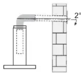
- Ako upute za instalaciju površine za kuhanje na plin specificiraju udaljenost veću od gore naznačene, potrebno je uvažiti. Moraju se poštovati svi propisi koji se odnose na ispust zraka.
- Koristite samo vijke i sitni materijal, koji odgovaraju napi.
Upozorenje: manjkava instalacija vijaka ili sredstava za učvršćivanje u skladu s ovim uputama može uzrokovati opasnost od električnih udara. - Spojite napu na mrežno napajanje preko dvopolne sklopke s udaljenošću među kontaktima od najmanje 3 mm.
UPORABA
- Usisna napa osmišljena je isključivo za kućnu uporabu s ciljem uklanjanja mirisa od kuhanja.
- Nikad ne koristite napu za svrhe drugačije od onih za koje je osmišljena.
- Nikad ne ostavljajte otvoreni plamen ispod nape kad je ona u funkciji.
- Regulirajte intenzitet plamena na način da ga usmjerite isključivo prema dnu posude za kuhanje, pazeći da ne izlazi sa strana.
natural_image
Illustration of a greenhouse with a pot and smokestack, crossed by a green X-shaped line (no text or symbols)natural_image
Technical line drawing of a mechanical component with a base and top plate (no text or symbols)Bušenje zida i pričvršćivanje stremena

Označite na zidu:
- okomitu liniju do stropa ili gornje površine u sredini područja predviđenog za montažu nape;
- vodoravnu liniju na: min. 650 mm od površine za kuhanje.
- Stavite kako je prikazano stremen 7.2.1 na 1-2 mm od stropa ili gornje površine, nivelirajući njegovo središte (ureze) na okomitoj referentnoj liniji.
- Označite središta otvora stremena.
- Stavite kako je prikazano stremen 7.2.1 na X mm ispod prvog stremena (X = visina gornje nape koja je dio opreme), nivelirajući njegovo središte (ureze) na okomitoj referentnoj liniji.
• Označite središta otvora stremena. - Označite kako je prikazano, referentnu točku na 116 mm od okomite referentne linije i 320 mm iznad vodoravne referentne linije.
- Ponovite ovu radnju na suprotnoj strani.
- Probušite ø 8 mm označene točke.
• Umetnite klinove 11 u otvore. - Pričvrstite donji stremen 7.2.1 koristeći vijke 12a (4,2 x 44,4) koji su dio opreme.
- Pričvrstite zajedno gornji stremen 7.2.1 i potporni stremen spoja 7.3 koristeći 2 vijka 12a (4,2 x 44,4) koji su dio opreme.
- Pričvrstite stremen 7.1 za učvršćivanje tijela nape pomoću 2 vijka 12a (4,2 x 44,4) i podloški 22 koje su dio opreme provjeravajući nivelaciju.
natural_image
Diagram showing a mechanical component with an inset view of a tool interacting with a green arrow (no text or symbols present)Montaža nape
natural_image
Hand inserting a green arrow on a device screen (no text or symbols visible)Filtar protiv mirisa (Verzija s filtriranjem)
ZAMJENA FILTRA PROTIV MIRISA S AKTIVNIM UGLJENOM
- Nije periv i nije obnovljiv, mijenja se bar svaka 4 mjeseca ili češće, kod posebno intenzivnog korištenja.
- Uklonite metalne filtre protiv masnoće.
- Uklonite zasićeni filtar protiv mirisa s aktivnim ugljenom, djelujući na posebne spojke.
- Stavite novi filtar tako da ga prikačite na njegovo mjesto.
- Ponovno namjestite metalne filtre protiv masnoće.
natural_image
Hand pressing a component on a green surface, no text or symbols visibleRasvjeta
ZAMJENA LAMPICA
Halogena žarulja od 20 W.
- Uklonite metalne filtre protiv masnoće.
- Odvrnite žarulje i zamijenite ih novima istih karakteristika.
- Ponovno namjestite metalne filtre protiv masnoće.

natural_image
Line drawing of a hand holding a tool, no text or symbols present| Žarulja | Apsorpcija (W)žarulje | Grotaža (V) Dimenzije(mm) | Sustav označavanja ILCOS | ||
| [2476] | 28 E14 220 | -240 104 x 35 | HSGSB/C/UB-28-220/240-E14 | ||
| [TOCH] | 28 | E14 | 230 | 85x25 | HDG-28-230-E14-25 |
| [22X8] | 20 G4 12 33 x 9 | HSG/C/UB-20-12-G4 | |||
 | 35 | GU10 | 230 | 51 x 50,7 | HAGS-35-230-GU10-51/40 |
| 50 | GU10 | 230 | 51 x 50,7 | HAGS-35-230-GU10-51/20 | |
 | 20 | GU4 | 12 | 40 x 35 | HRGS-20-12-GU4-35/30 |
| 20 GU5.3 | 12 | 46 x 51 | HRGS-20-12-GU5.3-50/10 | ||
| [19C0] | 16 | G13 | 95 | 720 x 26 | FD-16/40/1B-E-G13-26/720 |
| 18 | G13 | 57 | 589,8 x 26 | FD-18/40/1B-E-G13-26/600 | |
| [YSBC] | 9 | G23 | 60 (žarulja)220-240 (starter) | 167 x 28 | FSD-9/27/1B-I-G23 |
| 11 | G23 | 91 (žarulja)220-240 (starter) | 235,8 x 28 | FSD-11/40/1B-I-G23 | |
PRIPOROČILA IN NASVETI

natural_image
Illustration of a kitchen chimney emitting smoke with a green diagonal line crossing over it, next to a control panel (no text or symbols)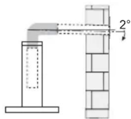
natural_image
Diagram of a pipe connection with a 2° angle indicator, showing structural components without any text or symbols.natural_image
Illustration of a greenhouse with a pot and smokestack, crossed by a green X (no text or symbols)natural_image
Simple line drawing of a T-shaped object with a height dimension labeled 70 (no text or symbols beyond the dimension)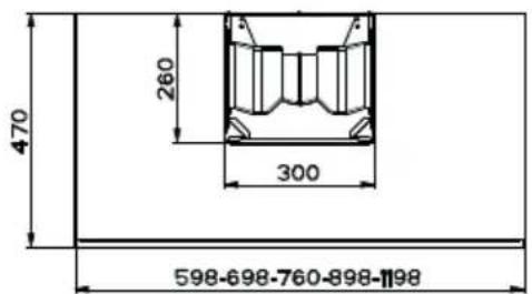
Sestavni deli
Ref. Kol. Sestavni deli izdelka
natural_image
Diagram showing a mechanical component with an inset view of a tool interacting with a green arrow (no text or symbols present)Namestitev dimnika
Zgornji dimnik
natural_image
Hand pressing a green arrow on a device screen (no text or symbols visible)natural_image
Illustration of a hand pressing a component on a green surface, with a green arrow indicating direction (no text or symbols)Osvetljava
MENJAVA ŽARNIC
28 W halogenska lučka.
natural_image
Line drawing of a hand holding a tool, no text or symbols present| Svetilka | Absorpcija (W) | Vtičnica | Napetost (V) | Mere (mm) | Koda ILCOS |
| [3WKX] | 28 E14 220 | -240 104 x 35 | HSGSB/C/UB-28-220/240-E14 | ||
 | 28 | E14 | 230 | 85x25 | HDG-28-230-E14-25 |
 | 20 G4 12 33 x 9 HSG/C/UB-20-12-G4 | ||||
 | 35 | GU10 | 230 | 51 x 50,7 | HAGS-35-230-GU10-51/40 |
| 50 | GU10 | 230 | 51 x 50,7 | HAGS-35-230-GU10-51/20 | |
 | 20 | GU4 | 12 | 40 x 35 | HRGS-20-12-GU4-35/30 |
| 20 GU5.3 | 12 | 46 x 51 HRGS-20-12-GU5.3-50/10 | |||
| [###] | 16 | G13 95 | 720 x 26 | FD-16/40/1B-E-G13-26/720 | |
| 18 | G13 57 | 589,8 x 26 | FD-18/40/1B-E-G13-26/600 | ||
| [###] | 9 | G23 | 60 (svetilka)220-240(zaganjalnik) | 167 x 28 | FSD-9/27/1B-I-G23 |
| 11 | G23 | 91 (svetilka)220-240(zaganjalnik) | 235,8 x 28 | FSD-11/40/1B-I-G23 | |

natural_image
Illustration of a chemical experiment setup with a conical flask, smoke, and a control unit (no text or symbols)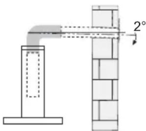
natural_image
Illustration of a greenhouse with a stove and smokestack, crossed by a green X (no text or symbols)natural_image
Simple line drawing of a tall rectangular object with a horizontal base, no text or symbols present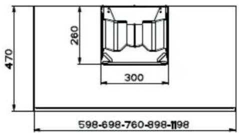

Делови
Озн. Кол. Делови производа
natural_image
Diagram showing a mechanical component with an inset view of a tool interacting with a green arrow (no text or symbols present)Склапање димњака
Горњи део димњака
natural_image
Hand holding a tablet device with a green arrow pointing to the screen (no text or symbols visible)natural_image
Illustration of a hand pressing a component on a green surface, with a green arrow indicating direction (no text or symbols)Осветљење
ЗАМЕНА СИЈАЛИЦА
natural_image
Line drawing of a hand holding a tool, no text or symbols present| Сијалица | Снага (W) | Грло | Напон (V) | Димензије (mm) | ILCOS ознака |
| [0256] | 28 | E14 | 220–240 | 104 x 35 | HSGSB/C/UB-28-220/240-E14 |
| [УКС7] | 28 | E14 | 230 | 85x25 HDG-28-230-E14-25 | |
| [УЗАВ] | 20 | G4 | 12 | HSG | 9 |
| 35 | GU10 | 230 | 51 x 50,7 | HAGS-35-230-GU10-51/40 |
| 50 | GU10 230 | 51 x 50,7 HAGS | 35-230-GU10-51/20 | ||
| 20 | GU4 | 12 | 40 x 35 | HRGS-20-12-GU4-35/30 |
| 20 | GU5.3 | 12 | 46 x 51 | HRGS-20-12-GU5.3-50/10 | |
| [IMAGE] | 16 | G13 | 95 | 720 x 26 | FD-16/40/1B-E-G13-26/720 |
| 18 | G13 | 57 589,8 x | 26 | FD-18/40/1B-E-G13-26/600 | |
| [IMAGE] | 9 | G23 | 60 (сијалица)220–240(стартер) | 167 x 28 | FSD-9/27/1B-I-G23 |
| 11 | G23 | 91 (сијалица)220–240(стартер) | 235,8 x 28 | FSD-11/40/1B-I-G23 |
CE