5DB69751 - Basket BLAUPUNKT - Free user manual and instructions
Find the device manual for free 5DB69751 BLAUPUNKT in PDF.
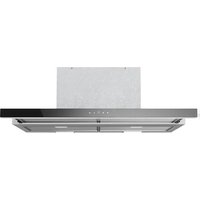
| Product type | Extractor hood |
| Brand | Blaupunkt |
| Model | 5DB69751 |
| Installation version | Extracting or recirculating (filtering) |
| Air outlet diameter | 150 mm (reducible to 120 mm) |
| Minimum safety distance | 650 mm above the cooking surface |
| Number of speeds | 3 (V1, V2, V3) |
| Lighting | Yes, with dedicated switch (L) |
| Grease filter type | Metal, dishwasher safe |
| Cleaning frequency of grease filters | Every 2 months (or more often depending on use) |
| Activated carbon filter type | Not washable, replaceable |
| Replacement frequency of charcoal filter | Every 4 months (or more often depending on use) |
| Power supply | Mains, voltage as per rating plate |
| Electrical class | I (earthing mandatory) |
| Installation | Wall-mounted, with mounting kit provided |
| Chimney type | Telescopic, two sections |
| Controls | Push buttons (L, S, V1, V2, V3) |
| Spare parts available | Yes: hood body, chimney, filters, lamps, mounting kit |
| Repairability | Filters and lamps replaceable by user |
| Manual available in multiple languages | Yes (FR, DE, EN, ES, IT, NL, etc.) |
Frequently Asked Questions - 5DB69751 BLAUPUNKT
User questions about 5DB69751 BLAUPUNKT
0 question about this device. Answer the ones you know or ask your own.
Ask a new question about this device
Download the instructions for your Basket in PDF format for free! Find your manual 5DB69751 - BLAUPUNKT and take your electronic device back in hand. On this page are published all the documents necessary for the use of your device. 5DB69751 by BLAUPUNKT.
USER MANUAL 5DB69751 BLAUPUNKT
Extractor hood 5DB69751
Hotte 5DB69751
Afzuigkap 5DB69751
RECOMMENDATIONS AND SUGGESTIONS 14
CHARACTERISTICS 17
INSTALLATION....18
USE 21
MAINTENANCE 22
INHALTSVERZEICHNIS
DE
natural_image
Technical line drawing of a T-shaped mechanical part with a 70-unit height dimension labeled (no text or symbols beyond the dimension)
Componenti

natural_image
Diagram showing a mechanical component with an inset view of a tool interacting with a green arrow (no text or symbols present)Montaggio Camino
Camino superiore
natural_image
Illustration of a hand pressing a green arrow on a smartphone screen (no text or symbols)Filtro antiodore (Versione Filtrante)
SOSTITUZIONE FILTRO ANTIODORE AL CARBONE ATTIVO
natural_image
Illustration of a hand pressing down on a green surface with a green arrow symbol (no text or labels)Illuminazione
natural_image
Line drawing of a hand using a tool to adjust or install a component, enclosed in a circular frame (no text or symbols)| Lampada | Assorbimento (W) | Attacco Voltaggio | (V) Dimensione (mm) | Codice ILCOS | |
| [3WHB] | 4 E14 220 | 240 107 x 37 | DRBB/F-4-220-240-E14-35/100 | ||
 | 5 GU10 230 | 52 x 50 | DRPAR-5/840-220/240-GU10-35/36DRPAR-5/830-220/240-GU10-35/36 |
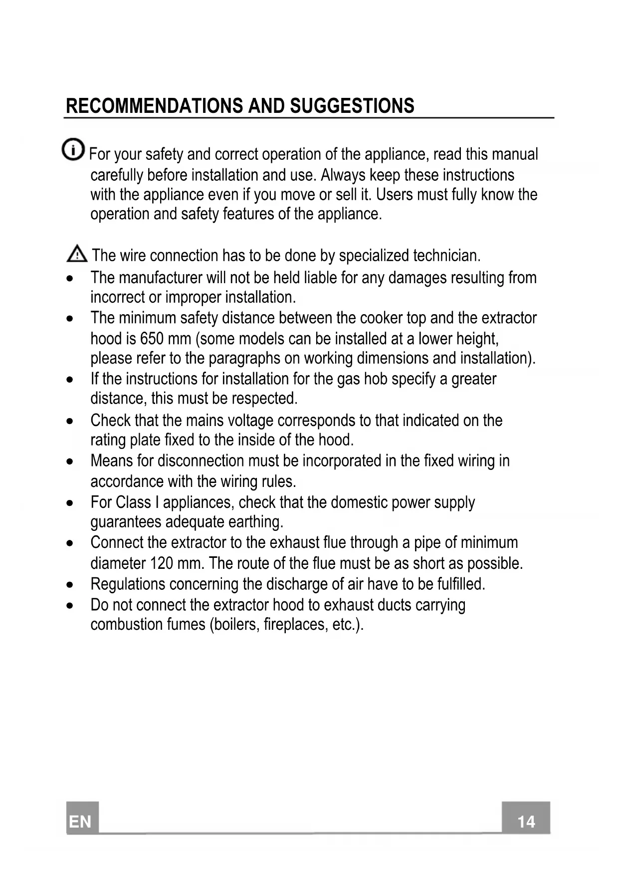
For your safety and correct operation of the appliance, read this manual carefully before installation and use. Always keep these instructions with the appliance even if you move or sell it. Users must fully know the operation and safety features of the appliance.
⚠ The wire connection has to be done by specialized technician.
- The manufacturer will not be held liable for any damages resulting from incorrect or improper installation.
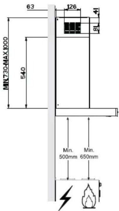
- The minimum safety distance between the cooker top and the extractor hood is 650 mm (some models can be installed at a lower height, please refer to the paragraphs on working dimensions and installation).
- If the instructions for installation for the gas hob specify a greater distance, this must be respected.
- Check that the mains voltage corresponds to that indicated on the rating plate fixed to the inside of the hood.
- Means for disconnection must be incorporated in the fixed wiring in accordance with the wiring rules.
- For Class I appliances, check that the domestic power supply guarantees adequate earthing.
- Connect the extractor to the exhaust flue through a pipe of minimum diameter 120 mm. The route of the flue must be as short as possible.
• Regulations concerning the discharge of air have to be fulfilled. - Do not connect the extractor hood to exhaust ducts carrying combustion fumes (boilers, fireplaces, etc.).
- If the extractor is used in conjunction with non-electrical appliances (e.g. gas burning appliances), a sufficient degree of aeration must be guaranteed in the room in order to prevent the backflow of exhaust gas. When the cooker hood is used in conjunction with appliances supplied with energy other than electric, the negative pressure in the room must not exceed 0,04 mbar to prevent fumes being drawn back into the room by the cooker hood.
- The air must not be discharged into a flue that is used for exhausting fumes from appliances burning gas or other fuels.
- If the supply cord is damaged, it must be replaced from the manufacturer or its service agent.
- Connect the plug to a socket complying with current regulations, located in an accessible place.
- With regards to the technical and safety measures to be adopted for fume discharging it is important to closely follow the regulations provided by the local authorities.
⚠ WARNING: Before installing the Hood, remove the protective films.
- Use only screws and small parts in support of the hood.
⚠ WARNING: Failure to install the screws or fixing device in accordance with these instructions may result in electrical hazards.
- Do not look directly at the light through optical devices (binoculars, magnifying glasses...).
- Do not flambè under the range hood; risk of fire.
- This appliance can be used by children aged from 8 years and above and persons with reduced physical, sensory or mental capabilities or lack of experience and knowledge if they have been given supervision or instruction concerning use of the appliance in a safe way and understand the hazards involved. Children shall not play with the appliance. Cleaning and user maintenance shall not be made by children without supervision.
- Children should be supervised to ensure that they do not play with the appliance.
- The appliance is not to be used by persons (including children) with reduced physical, sensory or mental capabilities, or lack of experience and knowledge, unless they have been given supervision or instruction.
⚠️ Accessible parts may become hot when used with cooking appliances.
- Clean and/or replace the Filters after the specified time period (Fire hazard). See paragraph Care and Cleaning.
- There shall be adequate ventilation of the room when the range hood is used at the same time as appliances burning gas or other fuels (not applicable to appliances that only discharge the air back into the room).
- The symbol 📂 on the product or on its packaging indicates that this product may not be treated as household waste. Instead it shall be handed over to the applicable collection point for the recycling of electrical and electronic equipment. By ensuring this product is disposed of correctly, you will help prevent potential negative consequences for the environment and human health, which could otherwise be caused by inappropriate waste handling of this product. For more detailed information about recycling of this product, please contact your local city office, your household waste disposal service or the shop where you purchased the product.
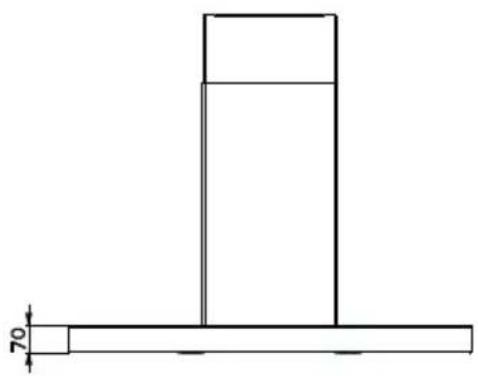
Dimensions
natural_image
Technical line drawing of a T-shaped mechanical part with a 70-unit height dimension labeled (no text or symbols beyond the dimension)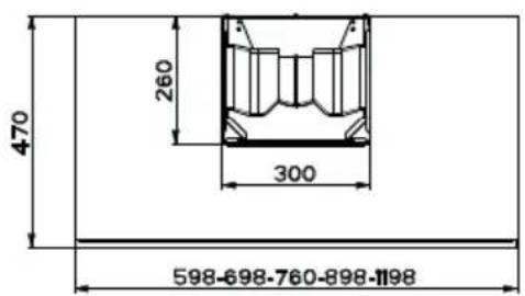
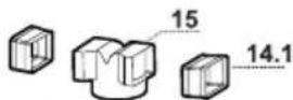
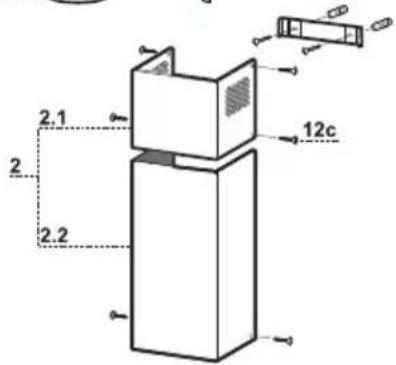
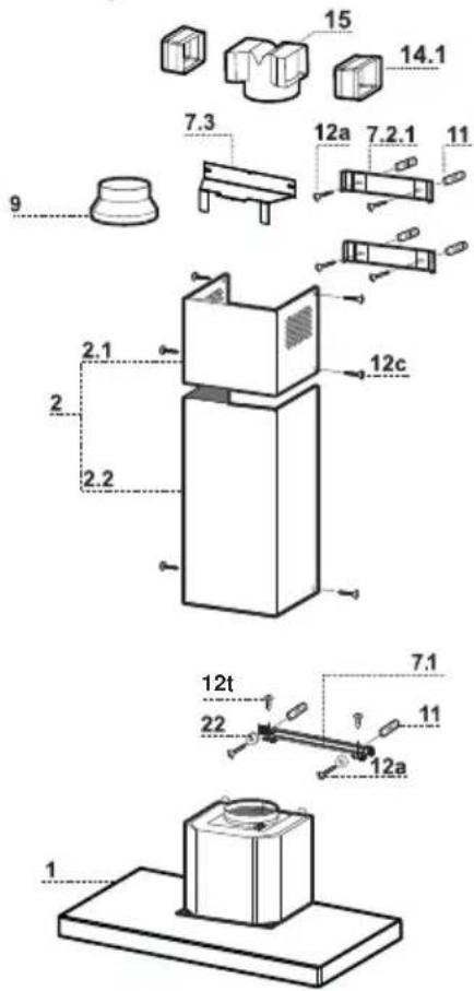
Components
| Ref. | Q.ty | Product Components | |
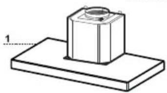
| 1 | 1 | Hood Body, complete with: Controls, Light, Blower, Filters | |
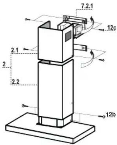
| 2 | 1 | Telescopic Chimney comprising: | |
| 2.1 | 1 | Upper Section | |
| 2.2 | 1 | Lower Section | |
| 9 | 1 | Reducer Flange ø 150-120 mm | |
| 14.1 | 2 | Air Outlet Connection Extension | |
| 15 | 1 | Air Outlet Connection | |
| Ref. | Q.ty | Installation Components | |
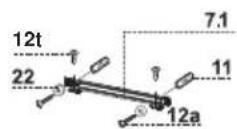
| 7.1 | 1 | Hood Body Fixing Brackets | |
| 7.2.1 | 2 | Upper Chimney Section Fixing Brackets | |
| 7.3 | 1 | Air Outlet Connection | |
| 11 | 6 | Wall Plugs | |
| 12a | 6 | Screws 4,2 x 44,4 | |
| 12c | 6 | Screws 2,9 x 6,5 | |
| 12e | 2 | Screws 2,9 x 9,5 | |
| 12t | 2 Screws 3,5 x 9,5 | ||
| 22 | 2 Washers | ||
| Q.ty | Documentation | ||
| 1 | Instruction Manual | ||


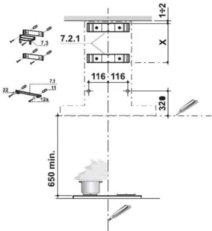
Wall drilling and bracket fixing
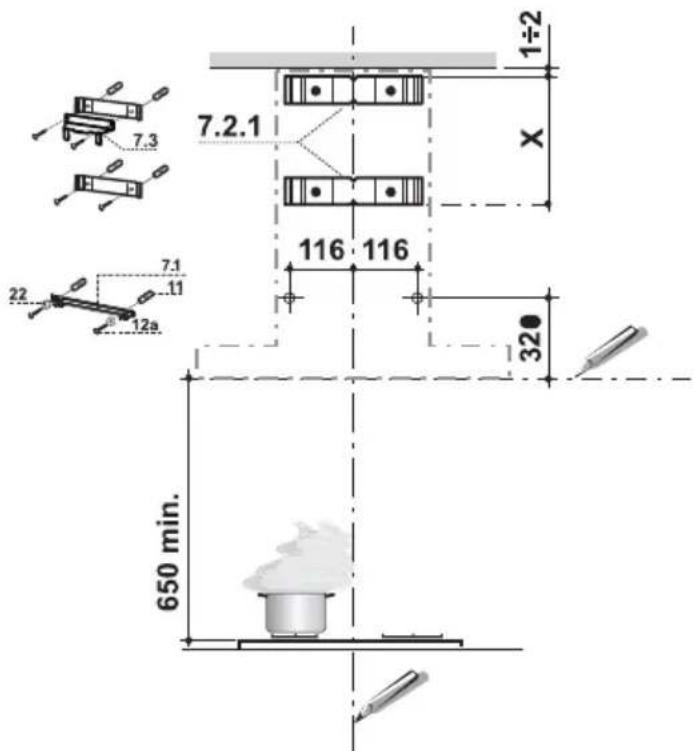
Wall marking:
- Draw a vertical line on the supporting wall up to the ceiling, or as high as practical, at the centre of the area in which the hood will be installed.
- Draw a horizontal line at 650 mm above the hob.
- Place bracket 7.2.1 on the wall as shown about 1-2 mm from the ceiling or upper limit aligning the centre (notch) with the vertical reference line.
- Mark the wall at the centres of the holes in the bracket.
- Place bracket 7.2.1 on the wall as shown at X mm below the first bracket (X = height of the upper chimney section supplied), aligning the centre (notch) with the vertical line.
- Mark the wall at the centres of the holes in the bracket.
- Mark a reference point as indicated at 116 mm from the vertical reference line and 320 mm above the horizontal reference line.
- Repeat this operation on the other side.
- Drill 8 mm holes at all the centre points marked.
- Insert the wall plugs 11 in the holes.
• Fix the lower bracket 7.2.1 using the 12a screws (4,2 x 44,4) supplied. - Fix the upper bracket 7.2.1 and the air outlet connection support 7.3 together using the 2 screws 12a (4,2 x 44,4) supplied.
- Fix the Hood Body Fixing Brackets 7.1 using the 2 screws 12a (4,2 x 44,4) and Washers 22 supplied, checking levelling.
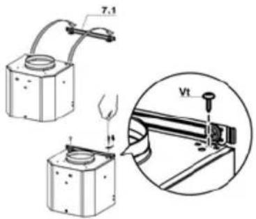
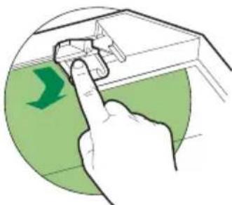
Installation with Bracket
- Hook the hood body onto the bracket 7.1 installed.
• Fix definitively the Hood body onto the bracket by 2 Screws 12t.
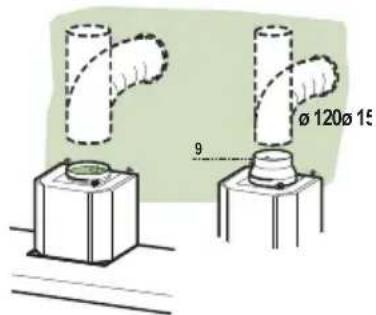
Connections
DUCTED VERSION AIR EXHAUST SYSTEM
When installing the ducted version, connect the hood to the chimney using either a flexible or rigid pipe 150 or 120 mm, the choice of which is left to the installer.
- To install a ø 120 mm air exhaust connection, insert the reducer flange 9 on the hood body outlet.
- Fix the pipe in position using sufficient pipe clamps (not supplied).
- Remove possible charcoal filters.
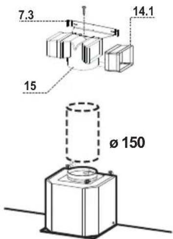
RECIRCULATION VERSION AIR OUTLET
- Insert the connection extension pieces laterally 14.1 in connection 15.
- Insert the Connector 15 into the Support bracket 7.3 and fix it with a screw.
- Make sure that the outlet of the extension pieces 14.1 is horizontally and vertically aligned with the chimney outlets.
- Connect the air outlet connection 15 to the hood body outlet using either a flexible or rigid pipe ∅ 150 mm, the choice of which is left to the installer.
- Ensure that the activated charcoal filters have been inserted.
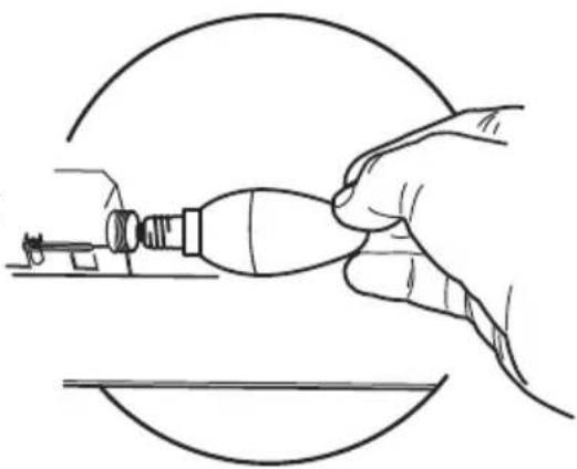
ELECTRICAL CONNECTION
- Connect the hood to the mains through a two-pole switch having a contact gap of at least 3 mm.
- Remove the grease filters (see paragraph Maintenance) being sure that the connector of the feeding cable is correctly inserted in the socket placed on the side of the fan.
natural_image
Diagram showing a mechanical component with an inset view of a tool interacting with a bracket (no text or symbols present)Flue assembly
Upper exhaust flue
- Slightly widen the two sides of the upper flue and hook them behind the brackets 7.2.1, making sure that they are well seated.
- Secure the sides to the brackets by using the 4 screws 12c (2,9 x 9,5) supplied.
- Make sure that the outlet of the extensions pieces is aligned with the chimney outlets.
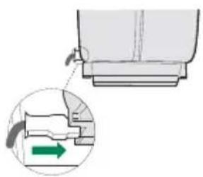
Lower exhaust flue
- Slightly widen the two sides of the flue and hook them between the upper flue and the wall, making sure that they are well seated.
- Fix the lower part laterally to the hood body by using the 2 screws 12c (2,9 x 9,5) supplied.
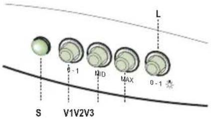
L Light Switches the lighting system on and off.
| S | Led | Motor running led. |
| V1 | Motor Switches the extractor motor on and off at low speed. Used to provide a continuous and silent air change in the presence of light cooking vapours. | |
| V2 | Speed | Medium speed, suitable for most operating conditions given the optimum treated air flow/noise level ratio. |
| V3 | Speed | Maximum speed, used for eliminating the highest cooking vapour emission, including long periods. |
Grease filters
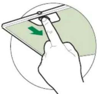
CLEANING METAL SELF- SUPPORTING GREASE FILTERS
- The filters must be cleaned every 2 months of operation, or more frequently for particularly heavy usage, and can be washed in a dishwasher.
- Remove the filters one at a time by pushing them towards the back of the group and pulling down at the same time.
- Wash the filters, taking care not to bend them. Allow them to dry before refitting.
- When refitting the filters, make sure that the handle is visible on the outside.
natural_image
Illustration of a hand pressing a green arrow on a smartphone screen (no text or symbols)Activated charcoal filter (Recirculation version)
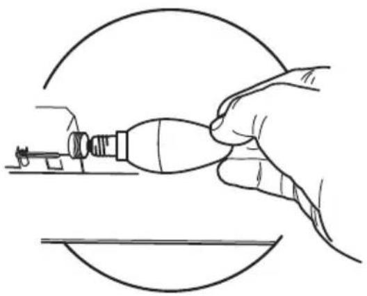
REPLACING THE ACTIVATED CHARCOAL FILTER
- The filter is not washable and cannot be regenerated, and must be replaced approximately every 4 months of operation, or more frequently for particularly heavy usage.
- Remove the metal grease filters.
- Remove the saturated activated carbon filter by releasing the fixing hooks.
• Fit the new filter by hooking it into its seating.
• Refit the metal grease filters.

natural_image
Illustration of a hand pressing down on a green surface with a green arrow symbol (no text or labels)Lighting
LIGHT REPLACEMENT
- Remove the metal grease filters.
- Unscrew the bulbs and replace them with new ones having the same characteristics.
- Replace the metal grease filters.
natural_image
Line drawing of a hand using a tool to adjust or install a component, enclosed in a circular frame (no text or symbols)| Lamp Power (W) Socket | Voltage (V) | Dimension (mm) | ILCOS Code | ||
| [3420] | 4 | E14 | 220-240 | 107 x 37 | DRBB/F-4-220-240-E14-35/100 |
 | 5 | GU10 | 230 | 52 x 50 | DRPAR-5/840-220/240-GU10-35/36DRPAR-5/830-220/240-GU10-35/36 |
natural_image
Technical line drawing of a T-shaped mechanical part with a 70-unit height dimension labeled (no text or symbols beyond the dimension)
Komponenten
natural_image
Isometric diagram of a mechanical component with a cylindrical top and base, labeled with number 1 (no text or symbols on the object itself)natural_image
Diagram showing a mechanical component with a green arrow indicating direction, no text or symbols presentKaminmontage
Oberer Kaminteil
natural_image
Hand holding a smartphone with a green arrow indicating left touch (no text or symbols)Geruchsfilter (Umluftversion)
natural_image
Illustration of a hand pressing down on a green surface with a green arrow symbol (no text or labels)Beleuchtung
AUSWECHSELN DER LAMPEN
natural_image
Line drawing of a hand using a tool to adjust or install a component, enclosed in a circular frame (no text or symbols)| Lampe Leistung (W) Fassung Spannung (V) | Größe (mm) ILCOS | Code | |||
| [3807] | 4 | E14 | 220-240 | 107 x 37 | DRBB/F-4-220-240-E14-35/100 |
 | 5 | GU10 | 230 | 52 x 50 | DRPAR-5/840-220/240-GU10-35/36DRPAR-5/830-220/240-GU10-35/36 |
natural_image
Technical line drawing of a T-shaped mechanical part with a 70-unit height dimension labeled (no text or symbols beyond the dimension)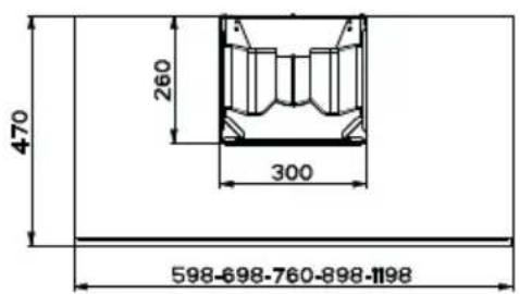
Composants

natural_image
Diagram showing a mechanical component with a green arrow indicating direction, no text or symbols presentMontage Cheminée
Cheminée supérieure
natural_image
Illustration of a hand pressing a green arrow on a smartphone screen (no text or symbols)Filtre anti-odeur (Version filtrante)
REPLACEMENT FILTRE AU CHARBON ACTIF
natural_image
Illustration of a hand pressing down on a green surface with a green arrow symbol (no text or labels)Eclairage
REMLACEMENT LAMPES
natural_image
Line drawing of a hand using a tool to adjust or install a component, enclosed in a circular frame (no text or symbols)| Ampoule Absorption (W) Culot Voltage (V) Dimensions (mm) Code ILCOS | |||||
 | 4 | E14 | 220-240 | 107 x 37 | DRBB/F-4-220-240-E14-35/100 |
 | 5 | GU10 | 230 | 52 x 50 | DRPAR-5/840-220/240-GU10-35/36DRPAR-5/830-220/240-GU10-35/36 |

natural_image
Technical line drawing of a T-shaped mechanical part with a 70-unit height dimension labeled (no text or symbols beyond the dimension)
Onderdelen
natural_image
Diagram showing a mechanical component with an inset view of a tool interacting with a green arrow (no text or symbols present)natural_image
Illustration of a hand pressing a green arrow on a smartphone screen (no text or symbols)Geurfilter (filterversie)
VERVANGING FILTER MET ACTIEVE KOOLSTOF
natural_image
Illustration of a hand pressing down on a green surface with a green arrow symbol (no text or labels)Verlichting
VERVANGING VAN DE LAMPEN
natural_image
Line drawing of a hand using a tool to adjust or install a component, enclosed in a circular frame (no text or symbols)| Lamp Stroomopname (W) Aansluiting Voltage (V) Afmeting (mm) ILCOS-code | |||||
| [Zx80] | 4 | E14 | 220-240 | 107 x 37 | DRBB/F-4-220-240-E14-35/100 |
 | 5 | GU10 | 230 | 52 x 50 | DRPAR-5/840-220/240-GU10-35/36DRPAR-5/830-220/240-GU10-35/36 |
natural_image
Pure technical line drawing of a T-shaped component with dimension标注 (no text or symbols)
Komponenter
Ref. Antal Produktkomponenter
natural_image
Diagram showing a mechanical component with a green arrow indicating direction, no text or symbols presentMONTERING AV SKORSTEN
natural_image
Illustration of a hand pressing a green arrow on a smartphone screen (no text or symbols)Kolfilter
natural_image
Illustration of a hand pressing down on a green surface with a green arrow symbol (no text or labels)Belysning
BYTE AV LAMPA
natural_image
Line drawing of a hand using a tool to adjust or install a mechanical component, no text or symbols present| Lampa Förbrukning (W) Sockel Spänning (V) Mått (mm) ILCOS art.nr | |||||
| [grswid] | 4 | E14 | 220-240 | 107 x 37 | DRBB/F-4-220-240-E14-35/100 |
 | 5 | GU10 | 230 | 52 x 50 | DRPAR-5/840-220/240-GU10-35/36DRPAR-5/830-220/240-GU10-35/36 |
natural_image
Technical line drawing of a T-shaped mechanical part with a 70-unit height dimension labeled (no text or symbols beyond the dimension)
Componentes
natural_image
Diagram showing a mechanical component with an inset view of a tool interacting with a bracket (no text or symbols present)natural_image
Illustration of a hand pressing a green arrow on a smartphone screen (no text or symbols)natural_image
Illustration of a hand pressing down on a green surface with a green arrow symbol (no text or labels)Iluminación
natural_image
Line drawing of a hand using a tool to adjust or install a mechanical component, enclosed in a circular frame (no text or symbols)| Lámpara Consumo de energía (W) Casquillo Voltaje (V) Dimensión (mm) Código ILCOS | |||||
 | 4 | E14 | 220-240 | 107 x 37 | DRBB/F-4-220-240-E14-35/100 |
 | 5 | GU10 | 230 | 52 x 50 | DRPAR-5/840-220/240-GU10-35/36DRPAR-5/830-220/240-GU10-35/3 |
natural_image
Technical line drawing of a T-shaped mechanical part with a 70-unit height dimension labeled (no text or symbols beyond the dimension)
Komponente
Bušenje zida i pričvršćivanje stremena
Označite na zidu:
natural_image
Diagram showing a mechanical component with an inset view of a tool interacting with a bracket (no text or symbols present)Montaža nape
natural_image
Hand holding a device with a green arrow indicating left motion (no text or symbols)Filtar protiv mirisa (Verzija s filtriranjem)
ZAMJENA FILTRA PROTIV MIRISA S AKTIVNIM UGLJENOM
- Nije periv i nije obnovljiv, mijenja se bar svaka 4 mjeseca ili češće, kod posebno intenzivnog korištenja.
- Uklonite metalne filtre protiv masnoće.
- Uklonite zasićeni filtar protiv mirisa s aktivnim ugljenom, djelujući na posebne spojke.
- Stavite novi filtar tako da ga prikačite na njegovo mjesto.
- Ponovno namjestite metalne filtre protiv masnoće.
natural_image
Illustration of a hand pressing down on a green surface with a green arrow symbol (no text or labels)Rasvjeta
ZAMJENA LAMPICA
- Uklonite metalne filtre protiv masnoće.
- Odvrnite žarulje i zamijenite ih novima istih karakteristika.
- Ponovno namjestite metalne filtre protiv masnoće.
natural_image
Line drawing of a hand using a tool to adjust or install a mechanical component, no text or symbols present| Žarulja | Apsorpcija (W)žarulje | Ghoutaža (V) Dimenzije(mm) | Sustav označavanja ILCOS | ||
 | 4 E14 220 | -240 107 x 37 | DRBB/F-4-220-240-E14-35/100 | ||
 | 5 GU10 230 | 52 x 50 | DRPAR-5/840-220/240-GU10-35/36DRPAR-5/830-220/240-GU10-35/36 | ||

natural_image
Pure technical line drawing of a T-shaped component with dimension标注 (no text or symbols)
Sestavni deli

Ref. Kol. Sestavni deli izdelka
natural_image
Diagram showing a mechanical component with an inset view of a tool interacting with a bracket (no text or symbols present)Namestitev dimnika
Zgornji dimnik
natural_image
Illustration of a hand pressing a green arrow on a smartphone screen (no text or symbols)natural_image
Illustration of a hand pressing down on a green surface with a green arrow symbol (no text or labels)Osvetljava
MENJAVA ŽARNIC
natural_image
Line drawing of a hand using a tool to adjust or install a mechanical component, enclosed in a circular frame (no text or symbols)| Svetilka | Absorpcija (W) | Vtičnica | Napetost (V) | Mere (mm) | Koda ILCOS |
 | 4 | E14 | 220-240 | 107 x 37 | DRBB/F-4-220-240-E14-35/100 |
| [XKBH] | 5 | GU10 | 230 | 52 x 50 | DRPAR-5/840-220/240-GU10-35/36DRPAR-5/830-220/240-GU10-35/36 |
natural_image
Technical line drawing of a T-shaped mechanical part with a 70-unit height dimension labeled (no text or symbols beyond the dimension)
Делови

natural_image
Diagram showing a mechanical component with an inset view of a tool interacting with a green arrow (no text or symbols present)Склапање димњака
Горњи део димњака
natural_image
Illustration of a hand pressing a green arrow on a smartphone screen (no text or symbols)natural_image
Illustration of a hand pressing a component on a green surface, with a green arrow indicating direction (no text or symbols)Осветљење
ЗАМЕНА СИЈАЛИЦА
- Уклоните металне филтере за маст.
- Одврните сијалице и замените их новима истих характеристика.
• Вратите металне филтере за маст.

natural_image
Line drawing of a hand using a tool to adjust or install a component, no text or symbols presentnatural_image
Close-up of blue fabric with a medical device labeled 'BLAUPUNKT' inserted into a clip (no other text or symbols visible)