
GDM500PS - Other computer accessories SONY - Free user manual and instructions
Find the device manual for free GDM500PS SONY in PDF.
| Product type | CRT monitor 21 inches |
| Brand | Sony |
| Model | GDM-500PS |
| Screen diagonal | 21 inches (19.8" viewable area) |
| Grille aperture pitch | 0.25 - 0.27 mm |
| Maximum resolution | 1600 x 1200 pixels |
| Horizontal frequency | 30 - 107 kHz |
| Vertical frequency | 48 - 160 Hz |
| Video input connectors | HD15 (VGA) and 5 BNC (RGB+sync) |
| Power supply | 100 - 240 V AC, 50/60 Hz, 2.0 - 1.0 A |
| Maximum power consumption | 145 W |
| Dimensions (W x H x D) | 498 x 505 x 474 mm |
| Weight | Approximately 31 kg |
| Display functions | Multilingual OSD menu, centering, size, geometry, zoom, color, convergence, moiré, purity adjustments |
| Automatic adjustment | ASC button to adjust size and centering |
| Energy saving | VESA DPMS, 3 power saving modes with LED indicator |
| Degaussing | Automatic at power-on, manual via menu |
| Maintenance and cleaning | Soft cloth and neutral detergent for the chassis; soft cloth for the screen, no antistatic products |
| Safety | Conforms to MPR II standards; do not block ventilation openings; use appropriate power cord |
| Swivel base | Horizontal rotation 180°, vertical 20° |
Frequently Asked Questions - GDM500PS SONY
User questions about GDM500PS SONY
0 question about this device. Answer the ones you know or ask your own.
Ask a new question about this device
Download the instructions for your Other computer accessories in PDF format for free! Find your manual GDM500PS - SONY and take your electronic device back in hand. On this page are published all the documents necessary for the use of your device. GDM500PS by SONY.
USER MANUAL GDM500PS SONY
Trinitron Color Graphic Display
Operating Instructions EN
Mode d'emploi F
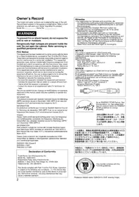
The model and serial numbers are located at the rear of the unit. Record the serial number in the space provided below. Refer to these numbers whenever you call upon your dealer regarding this product.
Model No. Serial No.
WARNING
To prevent fire or shock hazard, do not expose the unit to rain or moisture.
Dangerously high voltages are present inside the unit. Do not open the cabinet. Refer servicing to qualified personnel only.
FCC Notice
This equipment has been tested and found to comply with the limits for a Class B digital device, pursuant to Part 15 of the FCC Rules. These limits are designed to provide reasonable protection against harmful interference in a residential installation. This equipment generates, uses, and can radiate radio frequency energy and, if not installed and used in accordance with the instructions, may cause harmful interference to radio communications. However, there is no guarantee that interference will not occur in a particular installation. If this equipment does cause harmful interference to radio or television reception, which can be determined by turning the equipment off and on, the user is encouraged to try to correct the interference by one or more of the following measures:
- Reorient or relocate the receiving antenna.
- Increase the separation between the equipment and receiver.
- Connect the equipment into an outlet on a circuit different from that to which the receiver is connected.
- Consult the dealer or an experienced radio/TV technician for help. You are cautioned that any changes or modifications not expressly approved in this manual could void your authority to operate this equipment.
INFORMATION
This product complies with Swedish National Council for Metrology (MPR) standards issued in December 1990 (MPR II) for very low frequency (VLF) and extremely low frequency (ELF).
INFORMATION
This notice is applicable for USA/Canada only. If shipped to USA/Canada, install only a UL LISTED/CSA LABELLED power supply cord meeting the following specifications:
SPECIFICATIONS
Plug Type Nema-Plug 5-15p
Cord Type SVT or SJT, minimum 3·18 AWG
Length Maximum 15 feet
Rating Minimum 7 A, 125 V
NOTICE
As an ENERGY STAR Partner, Sony Corporation has determined that this product meets the ENERGY STAR guidelines for energy efficiency.

This monitor complies with the TCO 1992 guidelines for power saving when used with a computer equipped with VESA Display Power Management Signaling (DPMS).
(GDM-400PS only)

This monitor complies with the TCO'95 guidelines.
(GDM-500PS only)
Precautions 4
Identifying Parts and Controls 5
Setup 6
Automatically Adjusting the Size and Centering of the Picture 7
Selecting the On-screen Display Language 7
Selecting the Input Signal 8
Customizing Your Monitor
Adjusting the Picture Brightness and Contrast 9
Introducing the On-screen Display System 9
Using the CENTER On-screen Display 10
Using the SIZE On-screen Display 10
Using the GEOM (Geometry) On-screen Display 11
Using the ZOOM On-screen Display 12
Using the COLOR On-screen Display 12
Using the SCREEN On-screen Display 13
Using the OPTION On-screen Display 15
Using the LANG (Language) On-screen Display 17
Resetting the Adjustments 17
Technical Features
Preset and User Modes 18
Power Saving Function 19
Damper Wires 19
Plug & Play 19
Additional Information
Warning Messages 20
Troubleshooting 20
Self-diagnosis Function 22
Specifications 22
- Macintosh is a trademark licensed to Apple Computer, Inc., registered in the U.S.A. and other countries.
- Windows ^ and MS-DOS are registered trademarks of Microsoft Corporation in the United States and other countries.
- IBM PC/AT and VGA are registered trademarks of IBM Corporation of the U.S.A.
VESA is a trademark of Video Electronics Standard Association. - All other product names mentioned herein may be the trademarks or registered trademarks of their respective companies.
- Furthermore, "TM" and "®" are not mentioned in each case in this manual.
Precautions
Installation
- Prevent internal heat build-up by allowing adequate air circulation. Do not place the monitor on surfaces (rugs, blankets, etc.) or near materials (curtains, draperies) that may block the ventilation holes.
- Do not install the monitor near heat sources such as radiators or air ducts, or in a place subject to direct sunlight, excessive dust, mechanical vibration or shock.
- Do not place the monitor near equipment which generates magnetism, such as a transformer or high voltage power lines.
Maintenance
- Clean the cabinet, panel and controls with a soft cloth lightly moistened with a mild detergent solution. Do not use any type of abrasive pad, scouring powder or solvent, such as alcohol or benzine.
- Do not rub, touch, or tap the surface of the screen with sharp or abrasive items such as a ballpoint pen or screwdriver. This type of contact may result in a scratched picture tube.
- Clean the screen with a soft cloth. If you use a glass cleaning liquid, do not use any type of cleaner containing an anti-static solution or similar additive as this may scratch the screen's coating.
Transportation
When you transport this monitor for repair or shipment, use the original carton and packing materials.
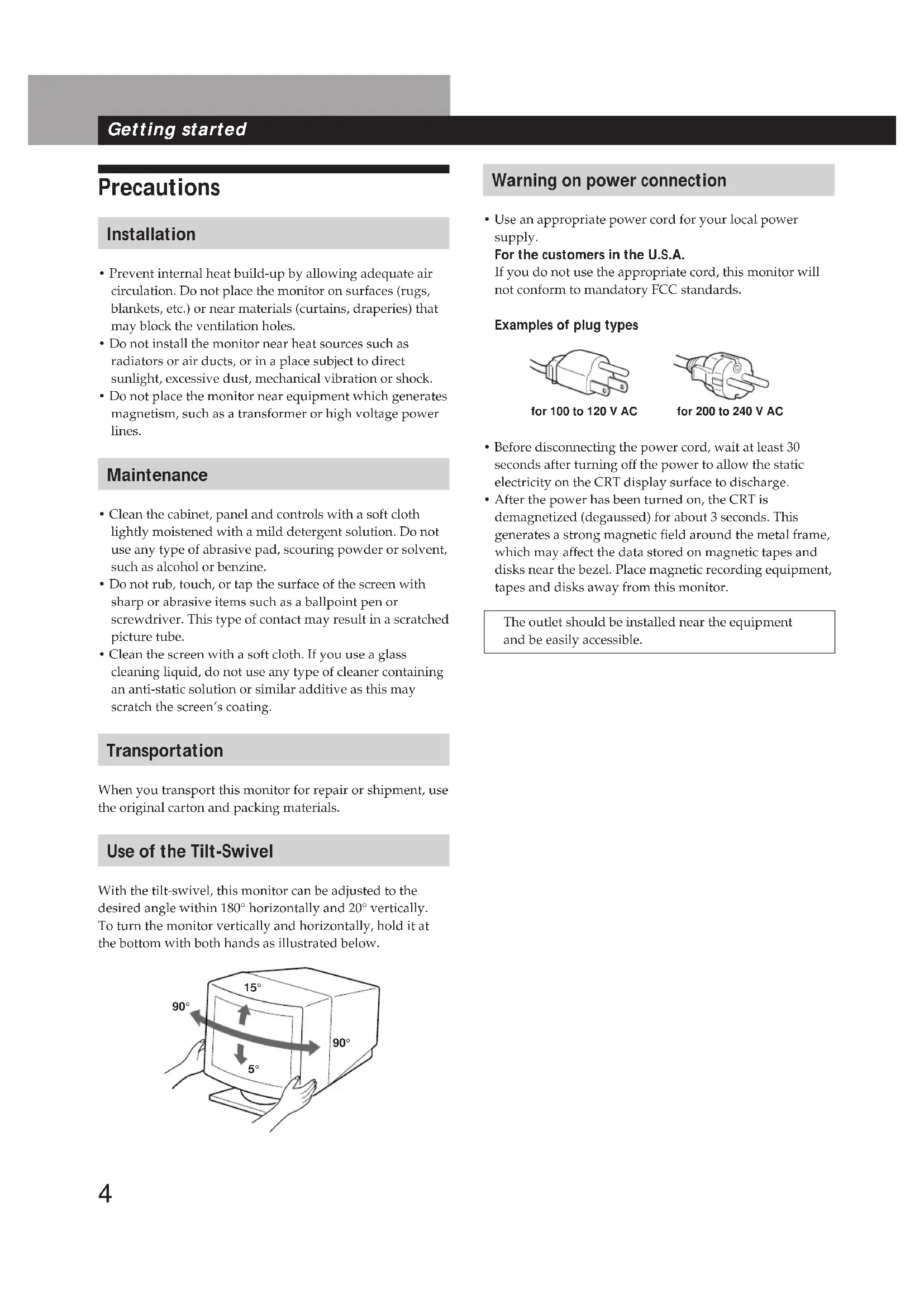
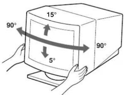
Use of the Tilt-Swivel
With the tilt-swivel, this monitor can be adjusted to the desired angle within 180^ horizontally and 20^ vertically. To turn the monitor vertically and horizontally, hold it at the bottom with both hands as illustrated below.
Warning on power connection
- Use an appropriate power cord for your local power supply.
For the customers in the U.S.A.
If you do not use the appropriate cord, this monitor will not conform to mandatory FCC standards.
Examples of plug types
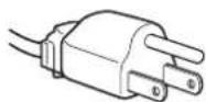
for 100 to 120 V AC

for 200 to 240 V AC
- Before disconnecting the power cord, wait at least 30 seconds after turning off the power to allow the static electricity on the CRT display surface to discharge.
After the power has been turned on, the CRT is demagnetized (degaussed) for about 3 seconds. This generates a strong magnetic field around the metal frame, which may affect the data stored on magnetic tapes and disks near the bezel. Place magnetic recording equipment, tapes and disks away from this monitor.
The outlet should be installed near the equipment and be easily accessible.
Identifying Parts and Controls
See the pages in parentheses for further details. GDM-500PS is used for illustration purposes throughout this manual.
Front
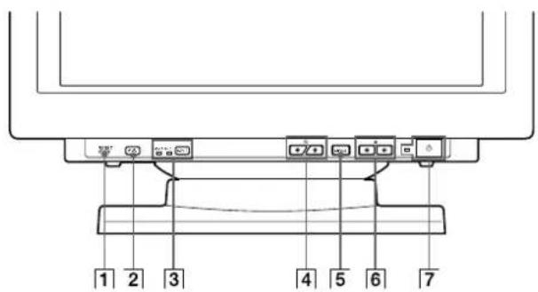
1 RESET (reset) button (page 17)
Resetstheadjustmentsto thefactory settings.
2 ASC (auto sizing and centering) button (page 7)
Automatically adjusts the size and centering of the images.
3 INPUT (input) button and HD15/BNC indicators (page 8)
Selects the HD15 or 5BNC video input signal. Each time you press this button, the input signal and corresponding indicator alternate.
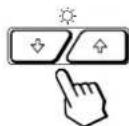
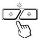
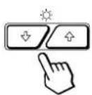
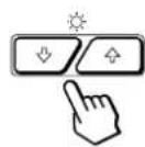
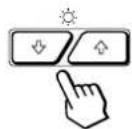
4 (brightness) ( / ) buttons (pages 8-17)
Adjust the picture brightness.
Function as the ( / ) buttons when adjusting other items.
5 MENU (menu) button (pages 8-17)
Displays the MENU OSD.
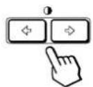
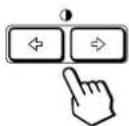
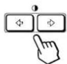
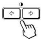
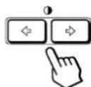
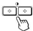
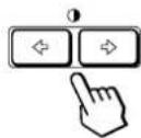
6 (contrast) ( / ) buttons (pages 8-17, 22)
Adjust the contrast.
Function as the ( / ) buttons when adjusting other items.
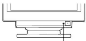
7 (power) switch and indicator (pages 19, 22)
Turns the monitor on or off.
The indicator lights up in green when the monitor is turned on, and either flashes in green and orange or lights up in orange when the monitor is in power saving mode.
Rear
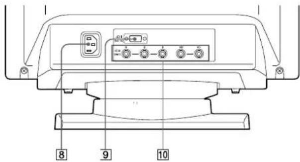
AC IN connector
Provides AC power to the monitor.
Video input 1 connector (HD15)
Inputs RGB video signals (0.700 Vp-p, positive) and SYNC signals.
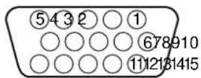
| Pin No. | Signal | Pin No. | Signal |
| 1 | Red | 8 | Blue Ground |
| 2 | Green (Composite Sync on Green) | 9 | DDC + 5V* |
| 10 | Ground | ||
| 11 | ID (Ground) | ||
| 3 | Blue | 12 | Bi-Directional Data (SDA)* |
| 4 | ID (Ground) | ||
| 5 | DDC Ground* | 13 | H. Sync |
| 6 | Red Ground | 14 | V. Sync |
| 7 | Green Ground | 15 | Data Clock(SCL)* |
- Display Data Channel (DDC) Standard of VESA
Video input 2 connector (5 BNC)
Inputs RGB video signals (0.700 Vp-p, positive) and SYNC signals.
Setup
Before using this monitor, check that the following items are included in your carton:
Monitor (1)
Power cord (1)
HD15 video signal cable (1)
- Macintosh adapter (1)
- Windows Monitor Information Disk (1)
TCO'95 Eco-document (1) (GDM-500PS only)
Warranty card (1)
These operating instructions (1)
This monitor works with any IBM or compatible system equipped with VGA or greater graphics capability. Although this monitor works with other platforms running at horizontal frequencies between 30 and 94kHz (GDM-400PS), 30 and 107kHz (GDM-500PS), including Macintosh and Power Macintosh systems, a cable adapter is required. Please consult your dealer for advice on which adapter is suitable for your needs.
Step 1: Connect the monitor to the computer
With the computer switched off, connect the video signal cable to the monitor using the supplied HD15 video signal cable.
If you are using an IBM PC/AT or compatible computer, refer to the section below.
If you are using a Macintosh or compatible computer, refer to the following section, "Connecting to a Macintosh or compatible computer."
- If you want to use the 5 BNC connectors, refer to the section, "Connecting to the 5 BNC connectors."
Connecting to an IBM PC/AT or compatible computer
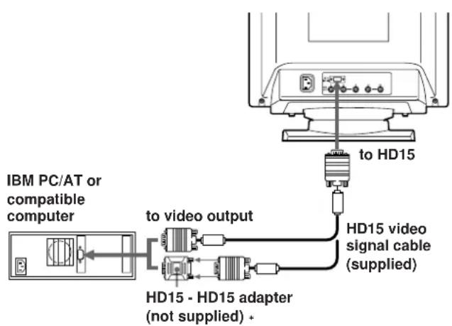
* The HD15 - HD15 adapter may be needed for some models.
If your PC system is not compatible with DDC2AB and DDC2B+
This monitor uses the No. 9 pin in the video signal connector for DDC2AB and DDC2B+ compatibility.
Some PC systems which are not compatible with either DDC2AB or DDC2B+ may not accept the No. 9 pin. If you are not sure whether your PC system accepts the No. 9 pin or not, use the HD15 (Female) - HD15 (Male without the No. 9 pin) adapter (not supplied). Make sure the male side (without the No. 9 pin) is connected to the computer.
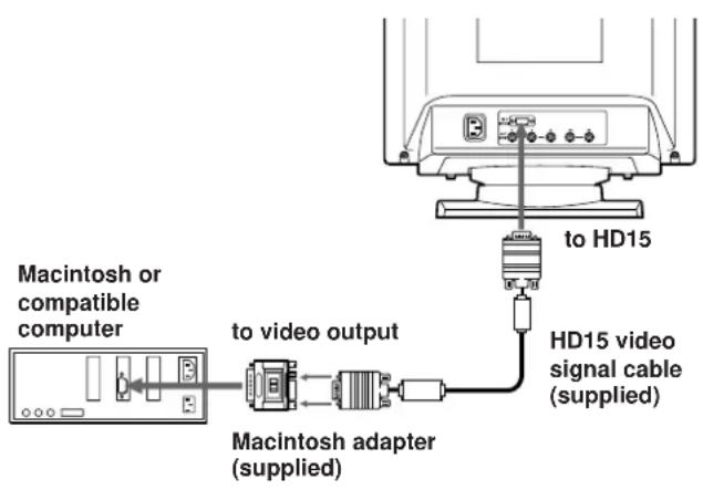
Connecting to a Macintosh or compatible computer
About the supplied Macintosh adapter
The supplied Macintosh adapter is compatible with Macintosh LC, Performa, Quadra, Power Macintosh and Power Macintosh G3 series computers.
Macintosh II series and some older versions of Power Book models may need an adapter with micro switches (not supplied).
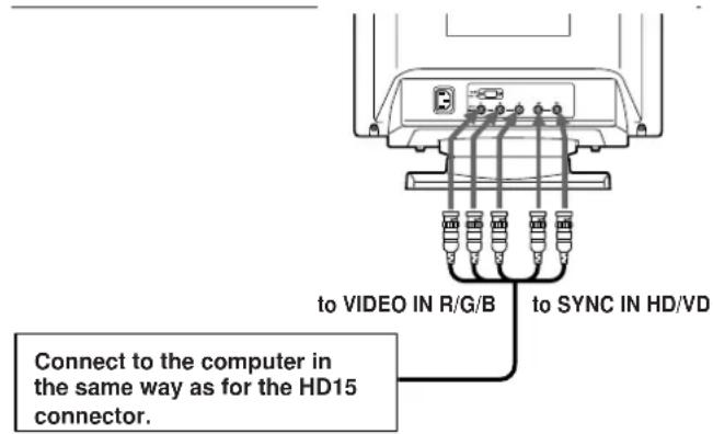
Connecting to the 5 BNC connectors
To connect the 5 BNC connectors, use the SMF-400 video signal cable (sold separately). Connect the cables from left to right in the following order: Red-Green-Blue-HD-VD.
Notes
- Do not short the pins of the video signal cable.
- The DDC standard does not apply to the 5 BNC connectors. If you use the DDC standard, connect the HD15 connector to the computer with the supplied video signal cable.
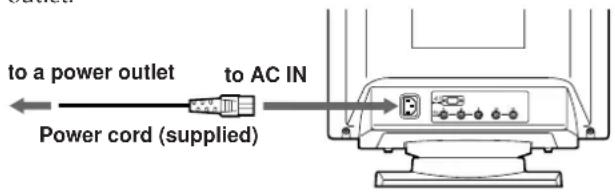
Step 2: Connect the power cord
With the monitor switched off, connect one end of the power cord to the monitor and the other end to a power outlet.
Step 3: Turn on the monitor and computer
The installation of your monitor is complete.
Note
If "OUT OF SCAN RANGE" or "NO INPUT SIGNAL" appears on the screen, see "Warning Messages" on page 20.
For customers using Windows 95/98
To maximize the potential of your monitor, install the new model information file from the supplied Windows Monitor Information Disk onto your PC.
This monitor complies with the "VESA DDC" Plug & Play standard. If your PC/graphics board complies with DDC, select "Plug & Play Monitor (VESA DDC)" or this monitor's model name as the monitor type in the "Control Panel" of Windows 95/98.
If your PC/graphics board has difficulty communicating with this monitor, load the Windows Monitor Information Disk and select this monitor's model name as the monitor type.
For customers using Windows NT4.0
Monitor setup in Windows NT4.0 is different from Windows 95/98 and does not involve the selection of monitor type. Refer to the Windows NT4.0 instruction manual for further details on adjusting the resolution, refresh rate, and number of colors.
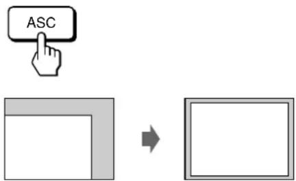
Automatically Adjusting the Size and Centering of the Picture
By pressing the auto sizing and centering (ASC) button, the size and centering of the picture are automatically adjusted to fit the screen.
1 Turn on the monitor and computer.
2 Press the ASC button.
The picture is adjusted to fit the center of the screen.
Notes
- This function is intended for use with a computer running Windows or similar graphic user interface software that provides a full-screen picture. It may not work properly if the background color is dark or if the input picture does not fill the screen to the edges (such as an MS-DOS prompt).
- The screen may go blank for a few seconds while performing the auto-sizing function. This is not a malfunction.
- Although the signals for picture aspect ratio 5:4 (resolution: 1280 - 1024) do not fill the screen to the edges, the picture is accurately displayed.
Selecting the On-screen Display Language
If you need to change the OSD language, see "Using the LANG (Language) On-screen Display" on page 17. The default setting is English.
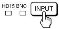
Selecting the Input Signal
This monitor has two signal input connectors (HD15 and 5BNC) and can be connected to two computers. When the power of both computers is on, select the input signal you want to view as follows.
1 Turn on the monitor and both computers.
2 Press the INPUT button to select the HD15 or 5BNC input signal.
Each time you press the INPUT button, the input signal and corresponding indicator alternate.
Selecting the INPUT signal mode
This monitor has two modes of input signal selection, "AUTO" and "MANUAL."
When "AUTO" is selected
If no signal is input from the selected connector, the monitor automatically selects the other connector's signal. When you restart the computer you want to view, or that computer is in power saving mode, the monitor may automatically select the other connector's signal. This is because the monitor switches from the interrupted signal to the constant signal. If this happens, manually select the desired signal using the INPUT button.
When "MANUAL" is selected
Even if no signal is input from the selected connector, the monitor does not select the other connector's signal.
1 Press the MENU button.
The MENU OSD appears.

2 Press the 口 / and / buttons to select "OPTION," and press the MENU button again. The OPTION OSD appears.
3 Press the buttons to select " (INPUT)."

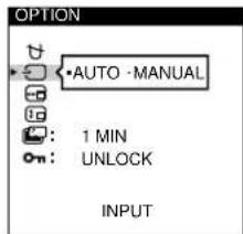
4 Press the 0 buttons to select "AUTO" or "MANUAL."
The OPTION OSD automatically disappears after about 30 seconds.
To close the OSD, press the MENU button again.
For more information on using the OSD, see "Introducing the On-screen Display System" on page 9.
Before adjusting
- Connect the monitor and the computer, and turn them on.
- Select "LANG" in the MENU OSD, then select
"ENGLISH" (see page 17).
Adjusting the Picture Brightness and Contrast
Once the setting is adjusted, it will be stored in memory for all input signals received.
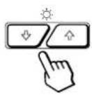
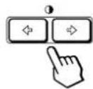
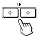
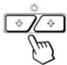
1 Press the (brightness) / or 0 (contrast) / buttons.
The BRIGHTNESS/CONTRAST OSD appears.
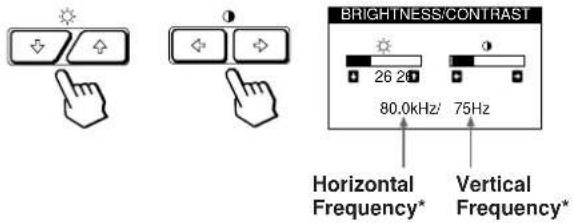
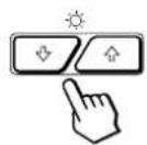
2 For brightness adjustment
Press the / buttons.
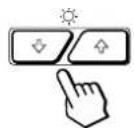
. .for more brightness
.for less brightness
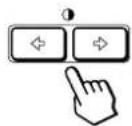
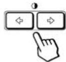
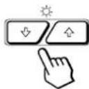
For contrast adjustment
Press the / buttons.
.for more contrast
... for less contrast
The OSD automatically disappears after about 3 seconds.
To reset, press the RESET button while the OSD is on. The brightness and contrast are both reset to the factory settings.
- The horizontal and vertical frequencies for the received input signal appear in the BRIGHTNESS/CONTRAST OSD.
Introducing the On-screen Display System
Most adjustments are made using the MENU OSD.
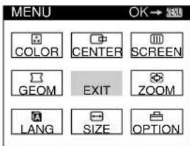
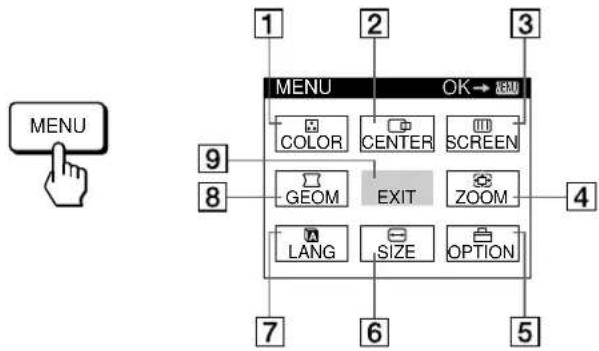
MENU OSD
Press the MENU button to display the MENU OSD.
This MENU OSD contains links to the other OSDs described below.
EN
1 COLOR
Displays the COLOR OSD for adjusting the color temperature.
2 CENTER
Displays the CENTER OSD for adjusting the centering of the picture.
3 SCREEN
Displays the SCREEN OSD for adjusting the vertical and horizontal convergence, etc.
4 ZOOM
Displays the ZOOM OSD for enlarging and reducing the picture.
5 OPTION
Displays the OPTION OSD for adjusting the OSD position and degaussing the screen, etc.
6 SIZE
Displays the SIZE OSD for adjusting the picture size.
7 ANLG
Displays the LANGUAGE OSD for selecting the language.
8 GEOM
Displays the GEOMETRY OSD for adjusting the picture rotation and pincushion, etc.
9 EXIT
Closes the MENU OSD.
Using the CENTER On-screen Display
The CENTER settings allow you to adjust the centering of the picture.
Once the setting is adjusted, it will be stored in memory for the current input signal.
1 Press the MENU button.
The MENU OSD appears.

2 Press the / and buttons to select "CENTER," and press the MENU button again.
The CENTER OSD appears.

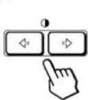
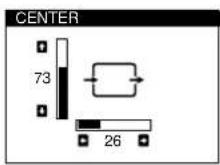
3 For horizontal adjustment
Press the / buttons.
to move the picture right to move the picture left
For vertical adjustment
Press the / buttons.
to move the picture up to move the picture down
The OSD automatically disappears after about 30 seconds. To close the OSD, press the MENU button again.
To reset, press the RESET button while the OSD is on. The horizontal and vertical centerings are both reset to the factory settings.
Using the SIZE On-screen Display
The SIZE settings allow you to adjust the size of the picture. Once the setting is adjusted, it will be stored in memory for the current input signal.
1 Press the MENU button.
The MENU OSD appears.

2 Press the / and / buttons to select "SIZE," and press the MENU button again.
The SIZE OSD appears.
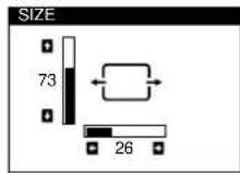
3 For horizontal adjustment
Press the / buttons.
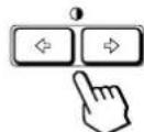
to increase picture size
.to decrease picture size
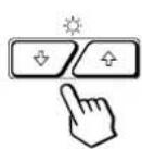
For vertical adjustment
Press the / buttons.
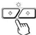
to increase picture size
.to decrease picture size
The OSD automatically disappears after about 30 seconds. To close the OSD, press the MENU button again.
To reset, press the RESET button while the OSD is on. The horizontal and vertical sizes are both reset to the factory settings.
Using the GEOM (Geometry) Onscreen Display
The GEOM (geometry) settings allow you to adjust the shape and orientation of the picture.
Once the rotation is adjusted, it will be stored in memory for all input signals received. All other adjustments will be stored in memory for the current input signal.
1 Press the MENU button.
The MENU OSD appears.

2 Press the / and / buttons to select "GEOM," and press the MENU button again.
The GEOMETRY OSD appears.
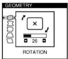
3 Press the 口 buttons to select the item you want to adjust.

| Select | To |
| ROTATION | adjust the picture rotation |
| PINCUSHION | adjust the picture sides |
| PIN BALANCE | adjust the picture side balance |
| KEYSTONE | adjust the picture width |
| KEY BALANCE | adjust the picture shape balance |
4 Press the buttons to adjust the settings.
| For | Press |
| ○ROTATION | →...to rotate the picture clockwise |
| ←...to rotate the picture counterclockwise | |
| × | |
| ←...to rotate the picture counterclockwise | |
| × | |
| □PINCUSHION | →...to expand the picture sides |
| ←○→ | |
| ←...to contract the picture sides | |
| →○ | |
| □PIN BALANCE | →...to move the picture sides to the right |
| →○→ | |
| ←...to move the picture sides to the left | |
| →○ | |
| □KEYSTONE | →...to increase the picture width at the top |
| ←○→ | |
| ←...to decrease the picture width at the top | |
| →○ | |
| □KEY BALANCE | →...to move the top of the picture to the right |
| ←○→ | |
| ←...to move the top of the picture to the left | |
| →○ |
The OSD automatically disappears after about 30 seconds. To close the OSD, press the MENU button again.
To reset, press the RESET button while the OSD is on. The selected item is reset to the factory setting.
Using the ZOOM On-screen Display
The ZOOM settings allow you to enlarge or reduce the picture.
Once the setting is adjusted, it will be stored in memory for the current input signal.
1 Press the MENU button.
The MENU OSD appears.

2 Press the / and / buttons to select "ZOOM," and press the MENU button again.
The ZOOM OSD appears.

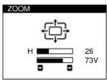
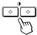
3 Press the buttons to adjust the picture zoom.
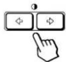
to enlarge the picture to reduce the picture
The OSD automatically disappears after about 30 seconds. To close the OSD, press the MENU button again.
To reset, press the RESET button while the OSD is on.
Note
The picture zoom adjustment will stop as soon as either the horizontal or vertical size reaches its maximum or minimum value.
Using the COLOR On-screen Display
You can change the monitor's color temperature. For example, you can adjust or change the colors of a picture on the screen to match the actual colors of the printed picture. Once the setting is adjusted, it will be stored in memory for all input signals received.
1 Press the MENU button.
The MENU OSD appears.

2 Press the / and 口 / buttons to select "COLOR," and press the MENU button again.
The COLOR OSD appears.
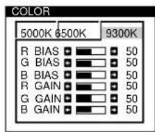
3 Press the / buttons to select the color temperature.
There are three color temperature modes in the OSD.
The preset adjustments are: 5000K, 6500K, 9300K
4 Fine tuning the color temperature
Press the / buttons to select an item and adjust by pressing the / buttons.
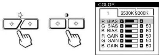
Select R (red), G (green), or B (blue) BIAS to adjust the black level of each color's signal.
Select R (red), G (green), or B (blue) GAIN to adjust the white level of each color's signal.
The "5000K," "6500K" or "9300K" disappears and the new color settings are memorized for each of the three color modes.
The color temperature modes change as follows:
$$ 5 0 0 0 \mathrm {K} \rightarrow 1, 6 5 0 0 \mathrm {K} \rightarrow 2, 9 3 0 0 \mathrm {K} \rightarrow 3 $$
The OSD automatically disappears after about 30 seconds. To close the OSD, press the MENU button again.
To reset, press the RESET button while the OSD is on. The selected item is reset to the factory settings.
Using the SCREEN On-screen Display
You can adjust convergence settings to eliminate red or blue shadows that may appear around objects on the screen.
Adjust the CANCEL MOIRE function to eliminate wavy or elliptical patterns that may appear on the screen.
Adjust the LANDING function to correct color imbalances at the four corners of the screen due to influence from the earth's magnetism.
Once CANCEL MOIRE is adjusted, it will be stored in memory for the current input signal. All other adjustments will be stored in memory for all input signals received.
1 Press the MENU button.
The MENU OSD appears.

2 Press the / and buttons to select "SCREEN," and press the MENU button again.
The SCREEN OSD appears.
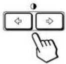
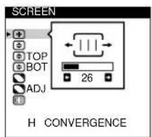
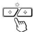
3 Press the / buttons to select the item you want to adjust.
| Select | To |
| H CONVERGENCE | adjust the horizontal convergence |
| ±V CONVERGENCE | adjust the vertical convergence |
| TOP | adjust the screen's upper vertical convergence |
| V CONVER TOP | |
| BOT | adjust the screen's lower vertical convergence |
| V CONVER BOTTOM |
(continued)
Customizing Your Monitor
| Select | To |
| LANDING | select one of the four corners that needs color correction due to influence from the earth's magnetism |
| ADJ | correct the color at one of the four corners of the screen |
| LANDING ADJUST | |
| CANCEL MOIRE* | turn the moire cancellation function “ON” or “OFF.” CANCEL MOIRE must be “ON” for “ADJ (MOIRE ADJUST)” to appear on the screen. |
| ADJ | adjust the degree of moire |
| MOIRE ADJUST | cancellation |
- Moire is a type of natural interference which produces soft or wavy lines on your screen. It may appear due to interference between the regulated pattern of the picture from the input signal and the phosphor pitch pattern of the CRT.
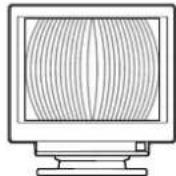
Example of moir:
4 Press the / buttons to adjust the settings.

| For | Press |
| H CONVERGENCE | →. . to shift red shadows to the right and blue shadows to the left |
| ←. . to shift red shadows to the left and blue shadows to the right | |
| V CONVERGENCE | →. . to shift red shadows up and blue shadows down |
| ←. . to shift red shadows down and blue shadows up | |
| TOP V CONVERTOP | →. . to shift red shadows up and blue shadows down |
| ←. . to shift red shadows down and blue shadows up |
| For | Press |
| BOT | →... to shift red shadows up and blue |
| V CONVER BOTTOM | shadows down |
| ←... to shift red shadows down and | |
| blue shadows up | |
| LANDING | →or←... to select the corner of the |
| screen you want to adjust | |
| top left: top right | |
| bottom left: bottom right | |
| ADJ | →or←... to reduce any irregularities in |
| LANDING ADJUST | the color to a minimum |
| CANCEL MOIRE | →... to turn CANCEL MOIRE "ON" |
| OFF ON | |
| ←... to turn CANCEL MOIRE "OFF" | |
| OFF ON | |
| ADJ | →or←... to adjust the screen until the |
| MOIRE ADJUST | moire is at a minimum |
Note
The picture may become fuzzy when CANCEL MOIRE is set to "ON."
The OSD automatically disappears after about 30 seconds. To close the OSD, press the MENU button again.
To reset, press the RESET button while the OSD is on. The selected item is reset to the factory setting.
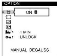
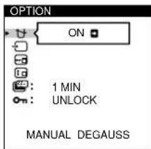
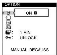
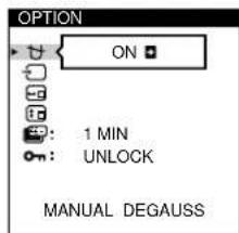
Using the OPTION On-screen Display
The OPTION OSD allows you to manually degauss the screen and adjust settings such as the OSD position and power saving delay time. It also allows you to lock the controls.
Degaussing the screen
The monitor screen is automatically degaussed (demagnetized) when the power is turned on. You can also manually degauss the monitor.
1 Press the MENU button.
The MENU OSD appears.

2 Press the / and / buttons to select "OPTION," and press the MENU button again.
The OPTION OSD appears.
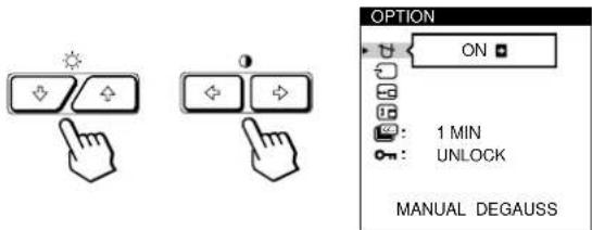
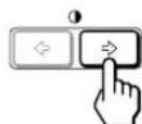
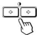
3 Press the / buttons to select " (MANUAL DEGAUSS).

4 Press the button.
The screen is degaussed for about 3 seconds.
If you need to degauss the screen a second time, wait for at least 20 minutes before repeating the steps above.
The OPTION OSD automatically disappears after about 30 seconds.
To close the OSD, press the MENU button again.
Changing the on-screen display position
You can change the OSD position (for example, when you want to adjust the picture behind the OSD).
1 Press the MENU button.
The MENU OSD appears.

2 Press the / and buttons to select "OPTION," and press the MENU button again.
The OPTION OSD appears.

3 Press the / buttons to select "OSD H POSITION" or "OSD V POSITION."
Select "OSD H POSITION" to adjust the horizontal position.
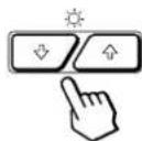
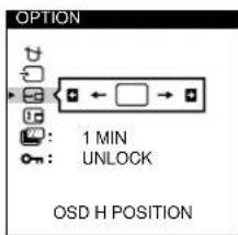
Select " (OSD V POSITION) to adjust the vertical position.
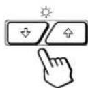
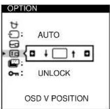
4 Press the buttons to move the OSD to the desired position.
The OPTION OSD automatically disappears after about 30 seconds.
To close the OSD, press the MENU button again.
To reset, press the RESET button while the OSD is on.
Setting the power saving delay time
You can set the delay time before the monitor enters the power saving mode. See page 19 for more information on this monitor's power saving capabilities.
1 Press the MENU button.
The MENU OSD appears.

2 Press the and buttons to select "OPTION," and press the MENU button again.
The OPTION OSD appears.
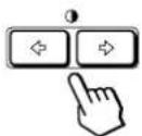
3 Press the buttons to select " (PWR SAVE DELAY).

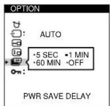
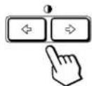
4 Press the / buttons to select the desired time.
When PWR SAVE DELAY is set to "OFF," the monitor does not go into power saving mode.
The OPTION OSD automatically disappears after about 30 seconds.
To close the OSD, press the MENU button again.
To reset, press the RESET button while the OSD is on.
Locking the controls
The control lock function disables all of the buttons on the front panel except the (power) switch and MENU button.
1 Press the MENU button.
The MENU OSD appears.

2 Press the / and / buttons to select "OPTION," and press the MENU button again.
The OPTION OSD appears.
3 Press the / buttons to select "ON (CONTROL LOCK).

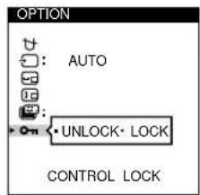
4 Press the 0 / buttons to select "LOCK."
The OPTION OSD automatically disappears after about 30 seconds.
To close the OSD, press the MENU button again.
Once you select "LOCK," you cannot select any items except "EXIT" and "OPTION" in the MENU OSD.
If you press any button other than the (power) switch and MENU button, the mark appears on the screen.
To cancel the control lock
Repeat steps 1 through 3 above and press the / buttons to select "UNLOCK."
Using the LANG (Language) Onscreen Display
English, French, German, Spanish, Italian and Japanese versions of the OSDs are available.
1 Press the MENU button.
The MENU OSD appears.

2 Press the / and / buttons to select "A LANG," and press the MENU button again.
The LANGUAGE OSD appears.
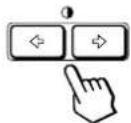
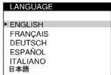
3 Press the 品 buttons to select the desired language.
ENGLISH: English, FRANÇAIS: French, DEUTSCH: German, ESPÁNOL: Spanish, ITALIANO: Italian, or 日本語: Japanese.
The OSD automatically disappears after about 30 seconds. To close the OSD, press the MENU button again.
To reset to English, press the RESET button while the OSD is on.
Resetting the Adjustments
Resetting an adjustment item
1 Press the MENU, and buttons to select the OSD containing the item you want to reset.

2 Press the / buttons to select the item you want to reset.
3 Press the RESET button.

Resetting all of the adjustment data for the current input signal
When there is no OSD displayed, press the RESET button.
All of the adjustments data for the current input signal is reset to the factory settings.
Note that adjustment data not affected by changes in input signal (OSD language, OSD position, input signal selection, power saving delay time and the control lock function) is not reset to the factory settings.

Resetting all of the adjustment data for all input signals
Press and hold the RESET button for more than two seconds.
All of the adjustment data, including the brightness and contrast, is reset to the factory settings.

Preset and User Modes
This monitor has factory preset modes for the most popular industry standards for true "plug and play" compatibility.
When a new input signal is entered, the monitor selects the appropriate factory preset mode and momentarily adjusts the phase calibration to provide a high quality picture to the center of the screen. The calibration is stored in memory and is immediately recalled whenever the same input signal is received.
| No. | Resolution (dots · lines) | Horizontal Vertical Frequency | Frequency | Graphics Mode |
| 1 | 640 · 350 | 31.5 kHz | 70 Hz | MCGA |
| 2 | 640 · 480 | 31.5 kHz | 60 Hz | VGA-G |
| 3 | 640 · 480 | 37.5 kHz | 75 Hz | EVGA |
| 4 | 640 · 480 | 43.3 kHz | 85 Hz | VESA |
| 5 | 720 · 400 | 31.5 kHz | 70 Hz | VGA-Text |
| 6 | 720 · 400 | 37.9 kHz | 85 Hz | VESA |
| 7 | 800 · 600 | 37.9 kHz | 60 Hz | SVGA |
| 8 | 800 · 600 | 46.9 kHz | 75 Hz | ESVGA |
| 9 | 800 · 600 | 53.7 kHz | 85 Hz | VESA |
| 10 | 832 · 624 | 49.7 kHz | 75 Hz | Macintosh 16" Color |
| 11 | 1024 · 768 | 48.4 kHz | 60 Hz | VESA |
| 12 | 1024 · 768 | 56.5 kHz | 70 Hz | VESA |
| 13 | 1024 · 768 | 60.0 kHz | 75 Hz | EUVGA |
| 14 | 1024 · 768 | 60.2 kHz | 75 Hz | Macintosh 19" Color |
| 15 | 1024 · 768 | 68.7 kHz | 85 Hz | VESA |
| 16 | 1152 · 864 | 67.5 kHz | 75 Hz | VESA |
| 17 | 1152 · 870 | 68.7 kHz | 75 Hz | Macintosh 21" Color |
| 18 | 1280 · 960 | 60.0 kHz | 60 Hz | VESA |
| 19 | 1280 · 960 | 85.9 kHz | 85 Hz | VESA |
| 20 | 1280 · 1024 | 64.0 kHz | 60 Hz | VESA |
| 21 | 1280 · 1024 | 80.0 kHz | 75 Hz | VESA |
| 22 | 1280 · 1024 | 91.1 kHz | 85 Hz | VESA |
| 23 | 1600 · 1200 | 75.0 kHz | 60 Hz | VESA |
| 24 | 1600 · 1200 | 81.3 kHz | 65 Hz | VESA |
| 25 | 1600 · 1200 | 87.5 kHz | 70 Hz | VESA |
| 26 | 1600 · 1200 | 93.8 kHz | 75 Hz | VESA |
| 27 * | 1600 · 1200 | 106.3 kHz | 85 Hz | VESA |
- GDM-500PS only
For input signals that do not match one of the factory preset modes, the digital Multiscan technology of this monitor performs all of the adjustments necessary to ensure that a clear picture appears on the screen for any timing in the monitor's frequency range. However, it may be necessary to fine tune the vertical/horizontal size and centering. Simply press the ASC button or adjust the monitor according to the adjustment instructions. The adjustments are stored automatically as a user mode and recalled whenever the corresponding input signal is received.
Recommended horizontal and vertical timing conditions
Horizontal sync width duty should be: >4.8% of total horizontal time.
Horizontal blanking width should be: >2.5 sec.
Vertical blanking width should be: >450~ sec
Note for Windows users
For Windows users, check your video board manual or the utility program which comes with your graphic board and select the highest available refresh rate to maximize monitor performance.
Adjusting the monitor's resolution and color number
Adjust the monitor's resolution and color number by referring to your computer's instruction manual. The color number may vary according to your computer or video board. The color palette setting and the actual number of colors are as follows:
High Color (16 bit) 65,536 colors
True Color (24 bit) about 16.77 million colors
In true color mode (24 bit), speed may be slower.
Power Saving Function
This monitor meets the power-saving guidelines set by VESA and Energy Star, as well as the more stringent NUTEK.
If the monitor is connected to a computer or video graphics board that is VESA DPMS (Display Power Management Signaling) compliant, the monitor will automatically reduce power consumption in three stages as shown below.
You can set the delay time before the monitor enters the power saving mode using the OSD. Set the time according to "Setting the power saving delay time" on page 16.
Note
If no video signal is input to the monitor, the "NO INPUT SIGNAL" message (page 20) appears. After the delay time has passed, the power saving function automatically puts the monitor into the active-off mode and the indicator lights up orange. Once the horizontal and vertical sync signals are detected, the monitor automatically resumes its normal operation mode.
| Power consumption mode | Screen | Horizontal sync signal | Vertical sync signal | Power consumption | Recovery time | \( \widehat{\mathbf{O}} \) indicator | |
| 1 | Normal operation | active | present | present | ≤ 145 W (GDM-500PS) \( \leq {125}\mathrm{\;W} \) (GDM-400PS) | - | Green |
| 2 | Standby (1st mode) | blank | absent | present | Approx. 72 W (GDM-500PS) Approx. 65 W (GDM-400PS) | Approx. 3 sec. | Green and orange alternate |
| 3 | Suspend (2nd mode) | blank | present | absent | Approx. 8 W | Approx. 3 sec. | Green and orange alternate |
| 4 | Active-off (3rd mode) | blank | absent | absent | Approx. 4 W | Approx. 10 sec. | Orange |
| 5 | Power-off | - | - | - | 0 W | - | Off |
EN
Damper Wires
When viewing a white background, very thin horizontal lines may be visible on the screen as shown below. These lines are the shadows of the damper wires and are characteristic of CRTs that use aperture grilles. The wires are attached to the aperture grille on the inside of the Trinitron tube and prevent the vibration of the aperture grille.
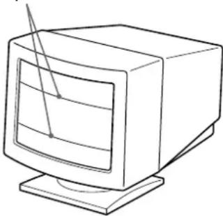
Damper wires
Plug & Play
This monitor complies with the DDC1, DDC2B, DDC2AB and DDC2B+ Display Data Channel (DDC) standards of VESA.
When a DDC1 host system is connected, the monitor synchronizes with the V. CLK in accordance with the VESA standards and outputs the EDID (Extended Display Identification Data) to the data line.
When a DDC2B, DDC2AB or DDC2B+ host system is connected, the monitor automatically switches to the appropriate standard.
DDCI is a trademark of the Video Electronics Standard Association.
Note
When using Windows 95/98, the DDC standard does not apply to the 5 BNC connectors. If you use the DDC standard, connect the HD15 connector to the computer with the supplied video signal cable.
Warning Messages
If there is something wrong with the input signal, one of the following messages appears.
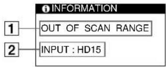
The input signal condition
"OUT OF SCAN RANGE" indicates that the input signal is not supported by the monitor's specifications.
"NO INPUT SIGNAL" indicates that no signal is input, or the input signal from the selected input connector is not received.
The selected input connector
Indicates which input connector is receiving the wrong signal. If there is something wrong with the signal from both input connectors, "HD15" and "BNC" are displayed alternately.
To solve these problems, see "Troubleshooting" below.
Troubleshooting
This section may help you isolate the cause of a problem and as a result, eliminate the need to contact technical support.
| Symptom Check these items | |
| No picture | |
| If the indicator is not lit | ·Check that the power cord is properly connected. ·Check that the (power) switch is in the "on" position. |
| If the "NO INPUT SIGNAL" message appears on the screen, or if the indicator is either orange or alternating between green and orange | ·The screen is blank when the monitor is in power saving mode. Try pressing any key on the computer keyboard. ·Check that your computer power switch is in the "on" position. ·Check that the input select setting is correct. ·Check that the video signal cable is properly connected and all plugs are firmly seated in their sockets. ·Check that the 5 BNCs are connected in the correct order (from left to right: Red-Green-Blue-HD-VD) (page 6). ·Ensure that no pins are bent or pushed in the HD15 video input connector. ·Check that the video board is completely seated in the proper bus slot. |
| If the "OUT OF SCAN RANGE" message appears on the screen | ·Check that the video frequency range is within that specified for the monitor. Horizontal: 30 - 94 kHz (GDM-400PS), 30 - 107 kHz (GDM-500PS) Vertical: 48 - 160 Hz Refer to your computer's instruction manual to adjust the video frequency range. ·If you are using a video signal cable adapter, check that it is correct. |
| If no message is displayed and the indicator is green or flashing orange | ·See "Self-diagnosis Function" (page 22). |
| If using a Macintosh system | ·Check that the Macintosh adapter and the video signal cable are properly connected (page 6). |
| If using Windows 95/98 | ·If you replaced an old monitor with this monitor, reconnect the old monitor and do the following. Install the Windows Monitor Information Disk (page 7) and select "GDM-400PS" or "GDM-500PS" from among the Sony monitors in the Windows 95/98 monitor selection screen. If you choose to select "Plug and Play," connect the monitor to the computer with the HD15 video signal. You cannot use the five BNC connectors. |
| Picture is scrambled | ·Check your graphics board manual for the proper monitor setting. ·Check this manual and confirm that the graphics mode and the frequency you are trying to operate at is supported. Even if the frequency is within the proper range, some video boards may have a sync pulse that is too narrow for the monitor to sync correctly. |
| Color is not uniform | Degauss the monitor (page 15).If you place equipment which generates a magnetic field, such as a loudspeaker, near the monitor, or you change the direction of the monitor, color may lose uniformity.The degauss function demagnetizes the metal frame of the CRT to obtain a neutral field for uniform color reproduction. If a second degauss cycle is needed, allow a minimum interval of 20 minutes for the best result.Adjust the landing (pages 13-14). |
| You cannot adjust the monitor with the buttons on the front panel | If the control lock function is set to on, set it to off using the OPTION OSD (page 16). |
| White does not look white | Adjust the color temperature (pages 12-13).Check that the 5 BNCs are connected in the correct order (from left to right: Red-Green-Blue-HD-VD) (page 6). |
| Screen image is not centered or sized properly | Press the ASC button (page 7).Adjust the size or centering (page 10).Some video modes do not fill the screen to the edges. This problem tends to occur with certain video boards. |
| Edges of the image are curved | Adjust the geometry (page 11). |
| White lines show red or blue shadows at edges | Adjust the convergence (pages 13-14). |
| Picture is fuzzy | Adjust the contrast and brightness (page 9).Degauss the monitor (page 15).If you place equipment which generates a magnetic field, such as a loudspeaker, near the monitor, or you change the direction of the monitor, color may lose uniformity.The degauss function demagnetizes the metal frame of the CRT to obtain a neutral field for uniform color reproduction. If a second degauss cycle is needed, allow a minimum interval of 20 minutes for the best result.If red or blue shadows appear along the edges of images, adjust the convergence (pages 13-14).If the moiré is cancelled, the picture may become fuzzy. Decrease the moiré cancellation effect (pages 13-14). |
| Picture bounces or has wavy oscillations | Isolate and eliminate any potential sources of electric or magnetic fields. Common causes for this symptom are electric fans, fluorescent lighting or laser printers.If you have another monitor close to this monitor, increase the distance between them to reduce the interference.Try plugging the monitor into a different AC outlet, preferably on a different circuit.Try the monitor on a different computer in a different room. |
| Picture is flickering | Set the refresh rate on the computer to obtain the best possible picture by referring to the computer's manual. |
| Picture appears to be ghosting | Eliminate the use of video cable extensions and/or video switch boxes if this symptom occurs. Excessive cable length or a weak connection can produce this symptom. |
| Wavy or elliptical (moire) pattern is visible | Cancel the moiré (pages 13-14).The moiré may be modified depending on the connected computer.Due to the relationship between resolution, monitor dot pitch and the pitch of some image patterns, certain screen backgrounds sometimes show moiré. Change your desktop pattern. |
| Two fine horizontal lines (wires) are visible | These wires stabilize the vertically striped aperture grille (page 19). This aperture grille allows more light to pass through to the screen giving the Trinitron CRT more color and brightness. |
| Hum is heard right after the power is turned on | When the power is turned on, the auto-degauss cycle is activated. While the auto-degauss cycle is activated (3 seconds), a hum may be heard. The same hum is heard when the monitor is manually degaussed. This is not a malfunction. |
Self-diagnosis Function
This monitor is equipped with a self-diagnosis function. If there is a problem with your monitor or computer(s), the screen will go blank and the indicator will either light up green or flash orange.
indicator
If the indicator is green
1 Remove any plugs from the video input 1 and 2 connectors, or turn off the connected computer(s).
2 Press and hold the button for 2 seconds.
If all four color bars appear (white, red, green, blue), the monitor is working properly. Reconnect the video input cables and check the condition of your computer(s).
If the color bars do not appear, there is a potential monitor failure. Inform your authorized Sony dealer of the monitor's condition.
If the indicator is flashing orange
Press the button to turn the monitor off and on.
If the indicator lights up green, the monitor is working properly.
If the indicator is still flashing, there is a potential monitor failure. Count the number of seconds between orange flashes of the indicator and inform your authorized Sony dealer of the monitor's condition. Be sure to note the model name and serial number of your monitor. Also note the make and model of your computer and video board.
Specifications
GDM-400PS
Picture tube 0.25 - 0.27mm aperture grille pitch
19 inches measured diagonally
90-degree deflection
Viewable image size Approx. 365 · 273 mm (w/h)
(14^3 / 8· 10^3 / 4 inches)
18.0" viewing image
Resolution Horizontal: Max. 1600 dots
Vertical: Max. 1200 lines
Standard image area Approx. 330· 264mm (w / h)
(13· 10^1 / 2 inches)
or
Approx. 352 · 264 mm( w/h)
(13^7 / 8 · 10^1 / 2 inches)
Deflection frequency Horizontal: 30 to 94kHz
Vertical: 48 to 160Hz
AC input voltage/current
100 to 240V 50 - 60Hz 1.8 - 1.0A
Power consumption Max. 125 W
Dimensions
444·467·453 mm (w/h/d)
(17^1 / 2· 18^1 / 2· 17^7 / 8 inches)
Mass Approx. 25kg (55 lb 2 oz)
Supplied accessories See page 6
GDM-500PS
Picture tube 0.25 - 0.27mm aperture grille pitch
21 inches measured diagonally
90-degree deflection
Viewable image size Approx. 403.8· 302.2mm (w / h)
(16·12 inches)
19.8" viewing image
Resolution Horizontal: Max. 1600 dots
Vertical: Max. 1200 lines
Standard image area Approx. 388· 291mm (w / h)
(15^3 / 8· 11^1 / 2 inches)
or
Approx. 364· 291mm (w / h)
(14^3 / 8· 11^1 / 2 inches)
Deflection frequency Horizontal: 30 to 107 J
Vertical: 48 to 160Hz
AC input voltage/current
100 to 240V 50 - 60Hz 2.0 - 1.0A
Power consumption Max. 145 W
Dimensions
498·505·474 mm (w/h/d)
(19^5 / 8· 20· 18^3 / 4 inches)
Mass Approx. 31kg (68 lb 5 oz)
Supplied accessories See page 6
Design and specifications are subject to change without notice.
TABLE DES MATIERES
Preparation
Resolution Horizontal: Max. 1600 pontos
Vertical: Max. 1200 linas
- Trinitron Color Graphic Display
- WARNING
- FCC Notice
- INFORMATION
- NOTICE
- Customizing Your Monitor
- Technical Features
- Additional Information
- Precautions
- Installation
- Maintenance
- Transportation
- Use of the Tilt-Swivel
- Warning on power connection
- Examples of plug types
- Identifying Parts and Controls
- Front
- Rear
- Setup
- Step 1: Connect the monitor to the computer
- About the supplied Macintosh adapter
- Notes
- Step 2: Connect the power cord
- Step 3: Turn on the monitor and computer
- Note
- For customers using Windows 95/98
- For customers using Windows NT4.0
- Automatically Adjusting the Size and Centering of the Picture
- Turn on the monitor and computer.
- Press the ASC button.
- Selecting the On-screen Display Language
- Selecting the Input Signal
- Selecting the INPUT signal mode
- When "AUTO" is selected
- When "MANUAL" is selected
- Before adjusting
- Adjusting the Picture Brightness and Contrast
- Press the (brightness) / or 0 (contrast) ← / → buttons.
- For brightness adjustment
- For contrast adjustment
- Introducing the On-screen Display System
- MENU OSD
- Press the MENU button to display the MENU OSD.
- COLOR
- CENTER
- SCREEN
- ZOOM
- OPTION
- SIZE
- ANLG
- GEOM
- EXIT
- Using the CENTER On-screen Display
- Press the MENU button.
- Press the / and → buttons to select "CENTER," and press the MENU button again.
- For horizontal adjustment
- For vertical adjustment
- Using the SIZE On-screen Display
- Press the / and ← / → buttons to select "SIZE," and press the MENU button again.
- Using the GEOM (Geometry) Onscreen Display
- Press the / and ← / → buttons to select "GEOM," and press the MENU button again.
- Press the 口 buttons to select the item you want to adjust.
- Press the → buttons to adjust the settings.
- Using the ZOOM On-screen Display
- Using the COLOR On-screen Display
- Fine tuning the color temperature
- Using the SCREEN On-screen Display
- Press the ← / → buttons to adjust the settings.
- Using the OPTION On-screen Display
- Degaussing the screen
- Press the / and ↔ / → buttons to select "OPTION," and press the MENU button again.
- Press the / buttons to select " (MANUAL DEGAUSS).
- Press the O→ button.
- The OPTION OSD automatically disappears after about 30 seconds.
- Changing the on-screen display position
- Press the / and → buttons to select "OPTION," and press the MENU button again.
- Press the / buttons to select "OSD H POSITION" or "OSD V POSITION."
- Press the O buttons to move the OSD to the desired position.
- Setting the power saving delay time
- Press the and → buttons to select "OPTION," and press the MENU button again.
- Press the buttons to select " (PWR SAVE DELAY).
- Press the O← /→ buttons to select the desired time.
- Locking the controls
- Press the / and ← / → buttons to select "OPTION," and press the MENU button again.
- Press the / buttons to select "ON (CONTROL LOCK).
- Press the 0← /→ buttons to select "LOCK."
- To cancel the control lock
- Using the LANG (Language) Onscreen Display
- Press the / and O ← / → buttons to select "A LANG," and press the MENU button again.
- Press the 品 buttons to select the desired language.
- Resetting the Adjustments
- Resetting an adjustment item
- Resetting all of the adjustment data for the current input signal
- When there is no OSD displayed, press the RESET button.
- Resetting all of the adjustment data for all input signals
- Press and hold the RESET button for more than two seconds.
- Preset and User Modes
- Recommended horizontal and vertical timing conditions
- Note for Windows users
- Adjusting the monitor's resolution and color number
- Power Saving Function
- Damper Wires
- Plug & Play
- Warning Messages
- The input signal condition
- The selected input connector
- Troubleshooting
- Self-diagnosis Function
- If the indicator is green
- If the indicator is flashing orange
- Specifications
- GDM-400PS
- GDM-500PS
- TABLE DES MATIERES
- Preparation
Brand : SONY
Model : GDM500PS
Category : Other computer accessories