
PCWADE30 - Other computer accessories SONY - Free user manual and instructions
Find the device manual for free PCWADE30 SONY in PDF.

| Product Type | Wireless LAN Converter (2.4 GHz) |
| Brand | Sony |
| Model | PCWA-DE30 |
| Dimensions (Wireless Unit) | Approx. 110 x 25 x 70 mm (W x H x D) |
| Dimensions (Power Supply Unit) | Approx. 98 x 98 x 33 mm (W x H x D) |
| Weight (Wireless Unit) | Approx. 320 g (including cable) |
| Weight (Power Supply Unit) | Approx. 130 g |
| Power Supply | AC 100-240 V, 50/60 Hz, approx. 5 W consumption |
| Interfaces | 1 Ethernet port 100BASE-TX/10BASE-T (Auto MDI/MDI-X) |
| Wireless Standards | IEEE 802.11b / IEEE 802.11g |
| Frequency Band | 2.4 to 2.4835 GHz (ISM band) |
| Encryption | WEP 64-bit / 128-bit |
| Protocol | TCP/IP |
| Operating Temperature | +5°C to +35°C (without condensation) |
| Storage Temperature | -20°C to +60°C (without condensation) |
| Key Features | Converts an Ethernet device into a wireless client; fast setup with Sony PCWA-A320 access point; setup utility for other access points; ad-hoc mode supported |
| Care and Cleaning | Avoid moisture and shocks; clean with a dry cloth if necessary |
| Safety | Use only the supplied AC adapter; do not expose to water; unplug in case of emergency |
| Spare Parts and Repairability | No spare parts specified; contact Sony support for any repairs |
| General Information | Designed to add wireless connectivity to an Ethernet device; does not function as an access point |
Frequently Asked Questions - PCWADE30 SONY
User questions about PCWADE30 SONY
0 question about this device. Answer the ones you know or ask your own.
Ask a new question about this device
Download the instructions for your Other computer accessories in PDF format for free! Find your manual PCWADE30 - SONY and take your electronic device back in hand. On this page are published all the documents necessary for the use of your device. PCWADE30 by SONY.
USER MANUAL PCWADE30 SONY
Wireless LAN Converter PCWA-DE30
Quick Start Guide Kurzeinführung Manuel de mise en route
CONTENTS
English -
Quick Start Guide ....page 3
Deutsch -
Kurzeinführung . . . . . . . . . . . . . . . . . . . . . . . . . . . . . . . . . . . . . . . . . . . . . . . . . . . . . . . . . . . . . . . . . . . . . . . . . . . . . . . . . .
Français -
- Sony, VAIO, the logo, that and the Eco Info logo are trademarks of Sony Corporation.
- Microsoft and Windows are registered trademarks of Microsoft Corporation in the United States and/or other countries.
- In this manual, Microsoft ^ Windows ^ XP Home Edition and Microsoft ^ Windows ^ XP Professional are referred to as Windows XP.
- All other names of systems, products and services are trademarks of their respective owners. In this manual the ^TM or ^® marks are not specified.
Introduction
This document provides an overview of the Wireless LAN Converter PCWA-DE30 features and the necessary configuration steps.
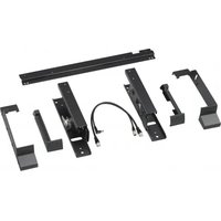
Unpacking your Access Point
Once you have unpacked the unit, make sure that all of the following items are present:
- Wireless Unit (1)
- Power cord (2)
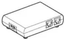
- Power Unit (3)
- Adapter plug*
• CD-ROM (setup disc) (4) - Quick Start Guide (4)
- Troubleshooting Guide (4)
- Warranty leaflet (4)
• Regulatory Leaflet (4)
*Depending on your country.
1
2
3
natural_image
Line drawing of a rectangular electronic device with two ports and a base (no text or symbols)4
Names of parts and functions
Wireless Unit
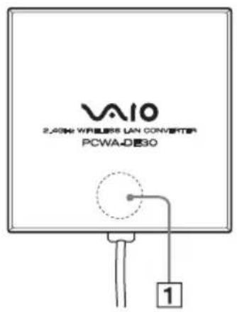
STATUS indicator (1) Indicates the status of the Wireless Converter.
White flashing (9 sec. lit, 1 sec. out) Wireless network connection status: good (strong signal).
White flashing (5 sec. lit, 1 sec. out) Wireless network connection status: Fair (medium signal).
White flashing (2 sec. lit, 1 sec. out) Wireless network connection status: Poor (weak signal).
White flashing (1 sec. lit, 9 sec. out) Nothing connected to the NETWORK connector or connected devices off.
White flashing Startup in progress. (half second intervals) Wait until startup is complete.
White flashing (0.2 sec. intervals) Wireless LAN Converter quick setup successful with the Quick Setup switch.
Pink lit Communicating in Peer to Peer Network connection mode.
Red flashing (6 sec. intervals) Wireless LAN Converter quick setup failed with the Quick Setup switch because it could not acquire setup information from the Access Point of the PCWA-A320.
Red flashing (3 sec. intervals) Search for wireless network in progress. Communication is not yet possible because connection is not established. If this condition continues for a long time, check the settings of the Wireless LAN Converter and the connection target (2.4 GHz Wireless LAN Access Point, etc.)
Red flashing (1.6 sec. Wireless LAN Converter in Quick Setup standby mode. intervals)
Red flashing (1 sec. intervals) Wireless LAN Converter firmware update failed. You must update the firmware again.
Red flashing (half sec. intervals)
Unit is resetting: When you release the reset switch, the Wireless LAN Converter restarts automatically and reverts to its factory default settings. Firmware update in progress: Firmware is being updated. Never turn off the power in this condition.
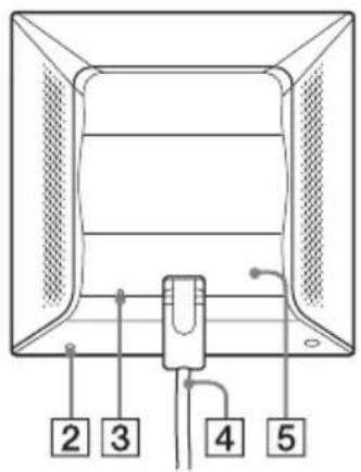
Reset switch (2) Returns the Wireless LAN Converter settings to their factory defaults.
LINK/ACT indicator (3) Lights when an Ethernet cable is connected to the NETWORK connector on the Power Unit.
Wireless unit cable (4) Connects to the WIRELESS UNIT connector on the Power Unit.
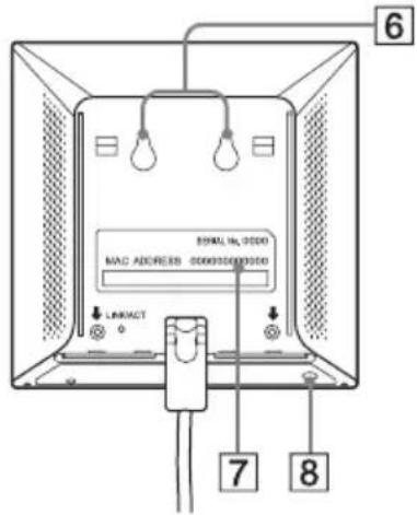
Rear cover (5) Remove this cover if you want to hang the Wireless Unit to a wall and to verify the MAC address.
Wall mounting holes (6) Use these holes to hang the Wireless Unit to the wall.
MAC address label (7) The Wireless LAN Converter MAC address is printed here.
Quick Setup switch (8) Use this switch to set up the Wireless LAN Converter.
Power Unit
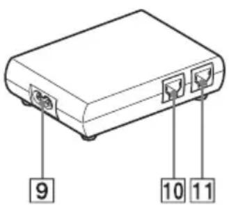
100-240 V AC jack (9) Connect the supplied power cord here.
WIRELESS UNIT connector (10) Connect the Wireless Unit cable here.
NETWORK connector (11) Connect the Wireless Unit to your computer or other device using an Ethernet cable.
Use a straight-through or crossover Ethernet cable.
Reset to factory default values
To reset to the Wireless LAN Converter factory default settings, proceed as follows:
1Turn on the Wireless LAN Converter.
2 Press the reset switch on the bottom of the Wireless Unit with the end of a paper clip or a similar object for at least one second.
3 When the status indicator begins flashing red, release the reset switch. The Wireless LAN Converter restarts automatically, and all settings revert to their factory default values.
- For details about the factory default settings of the Wireless LAN Converter, refer to the Troubleshooting Guide.
Capabilities
Wireless access to the Internet for devices with Ethernet connector
The 2.4 GHz Wireless LAN Converter PCWA-DE30 (hereafter referred to as the Wireless LAN Converter) is designed to allow devices such as desktop computer or printers equipped with Ethernet connectors to become part of a wireless network.
- Only use an Ethernet cable to connect the Wireless LAN Converter to the Ethernet device. The Wireless LAN Converter does not function as an Access Point.
When setting up the Wireless LAN Converter without the Quick Setup switch, a computer running Windows Me, Windows 2000, or Windows XP is required.
Only one device can be connected to the Wireless LAN Converter. You cannot use a hub to connect to several devices.
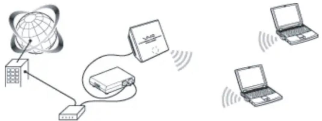
- The Wireless LAN Converter also allows computers equipped with Wireless LAN Converters to communicate directly when using the Peer to Peer Network connection mode, without using a Wireless LAN Access Point.
The Access Point Network connection mode settings are described in this document.
Refer to Help for information about the Peer to Peer Network connection mode settings.
Configuring the Wireless LAN Converter
You can configure the Wireless LAN Converter by performing one of the following.
With the Quick Setup switch
When the Wireless LAN Converter is connected to the Access Point PCWA-A320, you can use the Quick Setup switch to configure the Wireless LAN Converter.
You can use the settings of the Sony Access Point PCWA-A320 to automatically configure the hardwired (Ethernet) Wireless LAN Converter by using the Quick Setup switch. The Access Point send the following information to the Wireless LAN Converter.
• Network Name (SSID)
- Encryption key (WEP key)
With the utility software
When the Wireless LAN Converter is connected to an access point other than the PCWA-A320, you cannot use the Quick Setup switch to configure the Wireless LAN Converter. For details, see Configuration with the Utility Software below.
- You can use the utility software to configure the Wireless LAN Converter even if it is connected to the PCWA-A320.
Configuration with the Quick Setup Switch
When the Wireless LAN Converter is connected to the PCWA-A320, you can use the Quick Setup switch to configure it. When the Wireless LAN Converter is connected to another type of access point, see Configuration with the Utility Software below.
Procedure 1 - Completing the Access Point setup
Refer to the documentation of your Access Point for details about how to complete the setup. If your Access Point data encryption (WEP) is not configured, we strongly suggest that you configure it before proceeding.
Procedure 2 - Performing a Quick Setup
1 Wait until the PCWA-A320, and the Wireless LAN Converter starts.
2Press the Quick Setup switch of the PCWA-A320 Wireless Unit for at least one second.
When the status indicator on the PCWA-A320 starts flashing red, it is ready for Quick Setup.
The Wireless LAN Converter only remains in Quick Setup standby mode for 30 seconds.
Press the Quick Setup switch one more time for at least one second to cancel the procedure.
3 Press the Wireless LAN Converter Quick Setup switch for at least one second.
When the Status indicator on the PCWA-A320 stops flashing red and the Wireless LAN Converter begins flashing white, quick setup is complete.
4Turn off the Wireless LAN Converter.
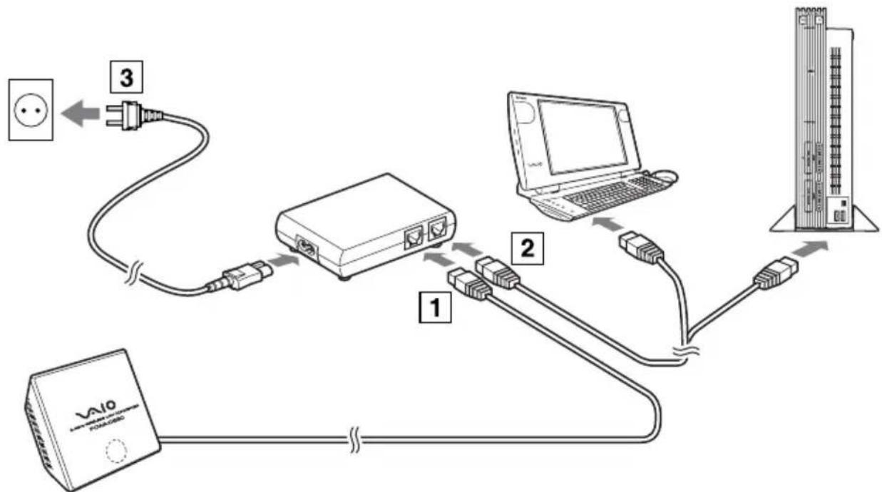
Procedure 3 - Connecting the Wireless LAN Converter to the device that you want to use for wireless communication
1Connect the Wireless Unit and Power Unit.
2Connect the Power Unit to the computer or other device capable of wireless communication using an Ethernet cable.
3Connect the Power Unit to an AC outlet using the power cord.
flowchart
graph TD
    A["Power Supply"] -->|3| B["Switch"]
    B -->|1| C["Laptop"]
    C -->|2| D["Server"]
    D -->|4| E["Data Tower"]
- The Wireless LAN Converter does not have a power switch.
You can use an Ethernet cable with straight-through or crossover wiring.
When the status indicator of the Wireless LAN Converter changes to white when you connect the wireless communication device, configuration is complete.
Configuration with the Utility Software
Procedure 1 - Verifying the computer used for setup and the Access Point, and configuring the necessary settings
Before setting up the Wireless LAN Converter with the Converter Setup Utility, verify the following points.
- Verify the Ethernet connector of the computer used for setup and provide the required Ethernet cable.
You can use an Ethernet cable with straight-through or crossover wiring.
- Verify the Access Point
Make sure that the 2.4 GHz Wireless LAN Access Point to be used is on. Also verify the Network Name (SSID) and Encryption (WEP) key settings of the Access Point.
If your Access Point data encryption (WEP) is not configured, we strongly suggest that you configure it before proceeding.
- Adjust the firewall settings of your computer If you are using the Windows XP Internet Connection Firewall function or a personal firewall provided by virus scanning software, it may be necessary to adjust its security level. For details, see below.
Computer Firewall Functions
When using the Windows XP Internet Connection Firewall function: enabling the Windows XP Internet Connection Firewall function may prevent you from accessing your computer through wireless communication (with the Windows XP operating system, this function is disabled by default). Because of this, you may not be able to connect to your network, when you change your Wireless LAN Converter and/or Access Point settings. If this happens, disable the Internet Connection Firewall function, connect to the network, and then reactivate the function. For details, refer to Windows XP Help.
- Network security is an important issue. You are urged to consider carefully how best to protect your computer.
When using a personal firewall provided by virus scanning or network security software: virus scanning and network security software sometimes included a function called a personal firewall that is designed to prevent illegal access by outside entities. Depending on the software, the security level of this function may be initially set to a high level. If this high security level setting is left in effect, it may be impossible for an outside entity to access your computer. This can cause problems such as not being able to connect to the network when changing the Wireless LAN Converter or Access Point settings. In this event, lower the security level in order to allow network connection. For details, refer to the manuals provided with your software.
- Network security is an important issue. You are urged to consider carefully how best to protect your computer. For details about firewall function or other inquiries, contact your software manufacturer.
Procedure 2 - Connecting the Wireless LAN Converter to the computer used for setup
Connect the Wireless LAN Converter and the computer.
- For details about how to connect the device that you want to use for wireless communication, see procedure 4.
Procedure 3 - Installing the utility software
Install the utility software to configure the Wireless LAN Converter (Converter Setup Utility) on the computer used for setup.
1 Insert the supplied CD-ROM into the CD-ROM drive of the computer where the Wireless LAN Converter is connected.
2With computers running Windows Me or Windows 2000, double-click the My Computer icon on your desktop.
With computers running Windows XP, click Start and My Computer.
3 In the My Computer window, double-click Setup.exe on the supplied CD-ROM.
The installation programs starts. Follow the instructions on the screen and install the utility software.
- Depending on the settings of your computer, the file Setup.exe may be displayed as Setup.
To exit the installation program, click Cancel.
Procedure 4 - Configuring the Wireless LAN Converter
Display the Wireless LAN Converter Setup Page and configure the necessary settings.
Compatible browsers:
- Internet Explorer 5.5 or later
• Netscape 6.1 or later - To display the Wireless LAN Converter Setup Page with the Converter Setup Utility software, use one of the Web browsers above.
If your Web browser is configured to use a proxy server, set the browser proxy settings so that the browser does not use a proxy server for the IP address of the Wireless LAN Converter and the 2.4 GHz Wireless LAN devices such as the Access Point. For details about how to disable proxy settings, see Case 4 in the Troubleshooting Guide.
- The Wireless LAN Converter Setup Page is saved in the internal memory of the Wireless LAN Converter.
- The page displayed may differ slightly depending on the firmware version of the Wireless LAN Converter.
1 Click Start, point to Programs (All Programs in Windows XP), point to Wireless LAN, and then click Converter Setup.
The Converter Setup Utility starts and automatically displays the Wireless LAN Converter Setup Page.
- If the IP Address Setup dialog box appears, temporarily change the converter IP address to the one in the dialog box. However, if you are using several devices to build a network, make sure that the new IP address does not duplicate the address of another device or computer on the network. If it does, you will not be able to open the Wireless LAN Converter Setup Page. Change the IP address as necessary before click Execute Setup.
If an error occurs, refer to the Troubleshooting Guide or Help.
2Click Easy Setup.
The Easy Setup page appears.
- You can select the interface language for the setup.
3Enter the Network Name (SSID) of your Access Point.
If the Access Point setup is complete: use the same Network name (SSID) as the one set for the Access Point.
If the Access Point setup is not complete: refer to the documentation provided with your Access Point and enter the default Network Name (SSID).
The Network name (SSID) is an identifier used to identify the wireless network. It is required for communication with the Access Point.
To search for active Access Points in the vicinity, click the Scan button.
4 Configure the Encryption (WEP), Key Length, and WEP key settings.
If the Access Point setup is complete: use the same values as the one set for the Access Point.
If the Access Point setup is not complete: refer to the documentation of the Access Point and enter the default values.
Encryption (WEP) Select whether to use data encryption or not.
Key Length Select the Encryption (WEP) key length. The number of characters for the key string depends on this setting.
WEP Key Enter a character string to be used as the Encryption (WEP) key. The length of the string must match the encryption ley length setting. For verification, the string must be entered once more in the WEP Key (Confirmation) field.
Encryption of wireless communications data (as selected by Encryption (WEP)). The length of the string must match the encryption key length setting.
For verification, the string must be entered once more in the WEP Key (Confirmation) field.
Clicking Help or ? displays Help.
5 When setup is complete, click Next.
The Setup confirmation page appears.
6 Make sure that the settings are as desired, and click Execute Setup.
The setup completion page appears.
When you click Execute Setup, the Wireless LAN Converter restarts.
If the status indicator on the front panel of the Wireless Unit flashes slowly, communication with the Access Point is established.
If the read-in condition continues after you click Execute Setup, check the status indicator on the front panel of the Wireless Unit. If the indicator flashes slowly white, setup is complete and wireless communication is possible.
If the status indicator flashes red, communication with the Access Point cannot be established. Refer to the Troubleshooting Guide or Help.
7Close the Web browser.
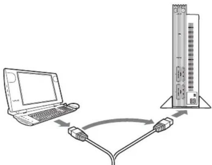
Procedure 5 - Connecting to a device equipped with an Ethernet connector
This procedure is unnecessary if you plan to perform a wireless communication session with the computer used for setup. If not, disconnect the Wireless LAN Converter from the computer used for setup and connect it to the wireless communication device.
flowchart
graph TD
    A["Laptop"] -->|USB cable| B["Industrial Control Unit"]
    B -->|USB cable to device| A
If you disconnect the Ethernet cable from the computer used for setup while it is still on, wait at least 10 seconds before connecting it to the wireless communication device.
If You Change the Access Point Settings
If you change the settings of your Access Point, the connection to the Wireless LAN Converter is severed. Reconfigure the Network Name (SSID) and Encryption key (WEP key) of the Wireless LAN Converter to match the values of your Access Point. If the Wireless LAN Converter is connected to the PCWA-A320, perform procedures 2 and 3 of Configuration with the Quick Setup Switch. If the Wireless LAN Converter is connected to a device other than the PCWA-A320, see Configuration with the Utility Software.
If you change the Access Point settings, see If You Change the Access Point Settings above.
If you want to reset the Wireless LAN Converter, see Reset to Factory Defaults above.
For details about the Wireless LAN Converter setup, refer to the Help.
To display Help, proceed as follows:
- Click Start, point to Programs (All Programs in Windows XP), point to Wireless LAN, and then click Converter Setup Help.
To display Help for the Wireless LAN Converter Setup Page, proceed as follows:
Click Help or ? on the Wireless LAN Converter Setup Page.
Installation precautions
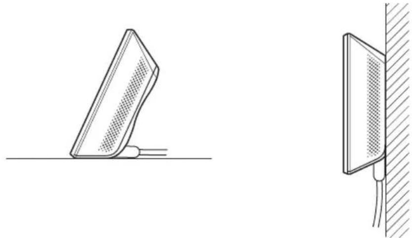
Installation
Select a secure location for the Wireless Unit where it cannot drop or fall over. Route the cable to the Wireless Unit to suit the installation location.
natural_image
Technical line drawing showing two views of a mechanical component, one with a flat surface and the other with a vertical wall and cable (no text or symbols)- Do not install the Wireless Unit or the Power Unit in insecure locations.
Do not install in a location where the Wireless Unit could fall as a result of shock or vibration, such as on the edge of a shelf.
Do not install the Wireless Unit in a location where it or its cables may hinder normal movement.
Prevent the Wireless Unit or the Power Unit from coming into contact with water.
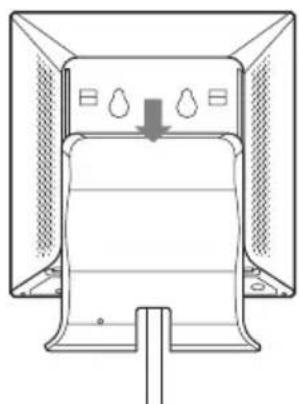
Hanging the Wireless Unit
1Remove the rear cover of the Wireless Unit by sliding it in the direction of the arrow.
Be cautious when removing and replacing the rear cover of the Wireless Unit.
To replace the rear cover of the Wireless Unit, align the rails on the rear of the Wireless Unit with the grooves in the rear cover, and slide it upwards.
natural_image
Diagram of a refrigerator with cooling fins and a downward arrow indicating airflow (no text or symbols)2Using screws or nails, hang the unit to a wall.
The Wireless Unit does not come with any sort of fittings used to hang it. Use screws of sufficient strength to support it.
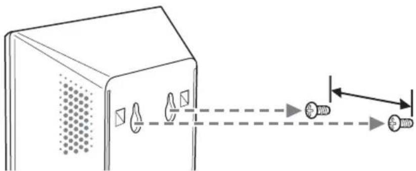
Always use two screws or nails and make sure that the unit is secure on the wall.
Select a location that will hold the weight of the Wireless Unit when hanging it to a wall. If the selected location cannot hold the weight of the unit, it may fall resulting in damage and/or injury.
When hanging the unit to walls made of plasterboard or other brittle material, make sure that the material is strong enough to support the unit's weight and use special screw fasteners or other fixtures designed for use with that material. If the unit is hung with ordinary screws, it may fall. When hanging the Wireless Unit to a wall, be careful not to drop the unit or the tools used for doing the work. Dropping the Wireless Unit or tools could result in damage and/or injury.
Operating Precautions
For more information on regulatory and safety issues, please read the Safety Regulations flyer before use.
Power Unit
Use the Power Unit supplied with the Wireless Unit. Using a different power unit may result in damage and/or injury.
Safety
Avoid exposing this product to strong impact, as it could result in damage which will not be covered by the guarantee.
Installation
Do not install the Wireless LAN Converter where it is exposed to the following conditions:
- Closed environments (such as closed cars);
- Magnetic fields (near magnets, speakers, or television);
- Microwaves (near microwaves ovens);
- Excessive dust;
- Unstable or uneven surfaces;
- Frequent vibration;
• High humidity (such as a bathroom); - Poor ventilation;
- Locations where the transmission of radio waves may be obstructed by metal plates or concrete walls.
Operation
Exposure to rapid changes in temperature or very damp environments can cause condensation on internal parts. This may prevent the Wireless LAN Converter from operating properly.
If this should happen, disconnect the Wireless LAN Converter from the converter or other device to which it may be connected, and discontinue operation for two or three hours.
Emergencies
In case of an emergency, stop the wireless functions by unplugging the power cord.
Specifications
Power AC100-240V, 5O/60Hz
Power consumption approx. 5 W
Interfaces 100BASE-TX/10BASE-T (automatic MDI/MDI-X detection)
Maximum external dimensions
Wireless Unit: approx. 110 x 25 x 70 mm. (W x H x D)
Power Unit: approx. 98 x 98 x 33 mm (W x H x D)
Mass
Wireless Unit: approx. 320 g (including connection cable)
Power Unit: approx. 130 g
Maximum connection distance Line of sight, approx. 100 m
(The actual connection distance depends on the environment)
Supported protocol TCP/IP
Standard compliance IEEE 802.11b
IEEE 802.11g
Radio frequency 2.4 GHz wireless network: 2.4 to 2.4835 GHz (ISM band)
WEP (data encryption) 64 bits/128 bits
Modulation methods DS-SS
OFDM
Operating temperature 5°C to 35°C (no condensation)
Storage temperature -20^ C to 60^ C (no condensation)
Design and specifications are subject to change without notice.
Sony's support options
This section describes how to get help and support from Sony.
- Quick Start Guide (this manual) : explains how to install the Wireless LAN Converter.
- Troubleshooting Guide : provides solutions to the most common problems users have with their Wireless LAN Converter.
- Online Help for the Wireless LAN Converter Setup Page : explains how to configure the Wireless LAN Converter.
- Sony's support website : http://www.vaio-link.com provides the latest information on your Wireless LAN Converter.
natural_image
Coiled cable with two connectors and a plug, labeled with number 2 (no text or symbols on the cable itself)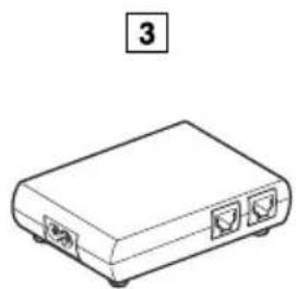
natural_image
Line drawing of a rectangular electronic device with two ports and a label '3' (no text or symbols on the device itself)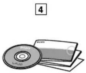
natural_image
Illustration of a CD and DVD disc (no text or symbols)natural_image
Technical line drawing showing two views of a mechanical component, one angled and one vertical, with no visible text or symbols.natural_image
Diagram of a device with ventilation ducts and a downward arrow indicating airflow or movement (no text or symbols)natural_image
Diagram of a device with sensor placements and directional arrows indicating alignment or interaction (no text or symbols)natural_image
Diagram showing network connection between a globe, network device, and two laptops with wireless signals (no text or labels)natural_image
Technical line drawing of a mechanical component with two views: one showing a flat base and the other showing a vertical wall with mesh texture (no text or symbols)natural_image
Diagram of a device with ventilation grilles and a downward arrow indicating airflow or cooling (no text or symbols)Distance de raccordement Sans obstacles, approx. 100 m
- Wireless LAN Converter PCWA-DE30
- Quick Start Guide Kurzeinführung Manuel de mise en route
- CONTENTS
- Introduction
- Unpacking your Access Point
- Names of parts and functions
- Wireless Unit
- Power Unit
- Reset to factory default values
- Capabilities
- Wireless access to the Internet for devices with Ethernet connector
- Configuring the Wireless LAN Converter
- With the Quick Setup switch
- With the utility software
- Configuration with the Quick Setup Switch
- Procedure 1 - Completing the Access Point setup
- Procedure 2 - Performing a Quick Setup
- Procedure 3 - Connecting the Wireless LAN Converter to the device that you want to use for wireless communication
- Configuration with the Utility Software
- Computer Firewall Functions
- Procedure 2 - Connecting the Wireless LAN Converter to the computer used for setup
- Procedure 3 - Installing the utility software
- Procedure 4 - Configuring the Wireless LAN Converter
- Procedure 5 - Connecting to a device equipped with an Ethernet connector
- If You Change the Access Point Settings
- Installation precautions
- Installation
- Hanging the Wireless Unit
- Operating Precautions
- Safety
- Operation
- Emergencies
- Specifications
- Sony's support options
Brand : SONY
Model : PCWADE30
Category : Other computer accessories