XAVAX8150 - Cd player/recorder SONY - Free user manual and instructions
Find the device manual for free XAVAX8150 SONY in PDF.
User questions about XAVAX8150 SONY
0 question about this device. Answer the ones you know or ask your own.
Ask a new question about this device
Download the instructions for your Cd player/recorder in PDF format for free! Find your manual XAVAX8150 - SONY and take your electronic device back in hand. On this page are published all the documents necessary for the use of your device. XAVAX8150 by SONY.
USER MANUAL XAVAX8150 SONY
To cancel the demonstration (Demo) display, see page 6.
text_image
Illustration showing a person confused with a question mark, next to a laptop displaying a login interface and a smartphone.
XAV-AX8150(EUR)
https://rd1.sony.net/help/ev/xav-ax81/h_zz/
text_image
* 5 0 2 5 7 0 9 3 1 * (1)Warning
For safety, be sure to install this unit in the dashboard of the car as the rear side of the unit becomes hot during use.
For details, see "Connection/Installation" (page 10).
Made in Thailand
The nameplate indicating operating voltage, etc., is located on the bottom of the chassis.
The validity of the CE marking is restricted to only those countries where it is legally enforced, mainly in the countries EEA (European Economic Area) and Switzerland.
WARNING
To prevent fire or shock hazard, do not expose the unit to rain or moisture.
To avoid electrical shock, do not open the cabinet. Refer servicing to qualified personnel only.
Notice for customers: the following information is only applicable to equipment sold in countries applying EU Directives
This product has been manufactured by or on behalf of Sony Corporation.
EU Importer: Sony Europe B.V.
Inquiries to the EU Importer or related to product compliance in Europe should be sent to the manufacturer's authorized representative, Sony Belgium, bijkantoor van Sony Europe B.V., Da Vincilaan 7-D1, 1930 Zaventem, Belgium.

Hereby, Sony Corporation declares that this equipment is in compliance with Directive 2014/53/EU.
The full text of the EU declaration of conformity is available at the following internet address:
https://compliance.sony.eu

Disposal of waste batteries and electrical and electronic equipment (applicable in the European Union and other countries with separate collection systems)
This symbol on the product, the battery or on the packaging indicates that the product and the battery shall not be treated as household waste.
On certain batteries this symbol might be used in combination with a chemical symbol. The chemical symbol for lead (Pb) is added if the battery contains more than 0.004% lead.
By ensuring that these products and batteries are disposed of correctly, you will help to prevent potentially negative consequences for the environment and human health which could be caused by inappropriate waste handling. The recycling of the materials will help to conserve natural resources.
In case of products that for safety, performance or data integrity reasons require a permanent connection with an incorporated battery, this battery should be replaced by qualified service staff only.
To ensure that the battery and the electrical and electronic equipment will be treated properly, hand over these products at end-of-life to the appropriate collection point for the recycling of electrical and electronic equipment.
For all other batteries, please view the section on how to remove the battery from the product safely. Hand the battery over to the appropriate collection point for the recycling of waste batteries.
For more detailed information about recycling of this product or battery, please contact your local Civic Office, your household waste disposal service or the shop where you purchased the product or battery.
Warning if your car's ignition has no ACC position
Do not install this unit in a car that has no ACC position. The display of the unit does not turn off even after turning the ignition off, and this causes battery drain.
Disclaimer regarding services offered by third parties
Services offered by third parties may be changed, suspended, or terminated without prior notice. Sony does not bear any responsibility in these sorts of situations.
Important notice
Caution
IN NO EVENT SHALL SONY BE LIABLE FOR ANY INCIDENTAL, INDIRECT OR CONSEQUENTIAL DAMAGES OR OTHER DAMAGES INCLUDING, WITHOUT LIMITATION, LOSS OF PROFITS, LOSS OF REVENUE, LOSS OF DATA, LOSS OF USE OF THE PRODUCT OR ANY ASSOCIATED EQUIPMENT, DOWNTIME, AND PURCHASER'S TIME RELATED TO OR ARISING OUT OF THE USE OF THIS PRODUCT, ITS HARDWARE AND/OR ITS SOFTWARE.
Dear customer, this product includes a radio transmitter.
According to UNECE Regulation no. 10, a vehicle manufacturers may impose specific conditions for installation of radio transmitters into vehicles.
Please check your vehicle operation manual or contact the manufacturer of your vehicle or your vehicle dealer, before you install this product into your vehicle.
Emergency calls
This BLUETOOTH car handsfree and the electronic device connected to the handsfree operate using radio signals, cellular, and landline networks as well as user-programmed function, which cannot guarantee connection under all conditions. Therefore do not rely solely upon any electronic device for essential communications (such as medical emergencies).
On BLUETOOTH communication
- Microwaves emitting from a BLUETOOTH device may affect the operation of electronic medical devices. Turn off this unit and other BLUETOOTH devices in the following locations, as it may cause an accident.
- where inflammable gas is present, in a hospital, train, airplane, or petrol station - near automatic doors or a fire alarm
- This unit supports security capabilities that comply with the BLUETOOTH standard to provide a secure connection when the BLUETOOTH wireless technology is used, but security may not be enough depending on the setting. Be careful when communicating using BLUETOOTH wireless technology.
- We do not take any responsibility for the leakage of information during BLUETOOTH communication.
If you have any questions or problems concerning your unit that are not covered in this manual, consult your nearest Sony dealer.
Main Unit
text_image
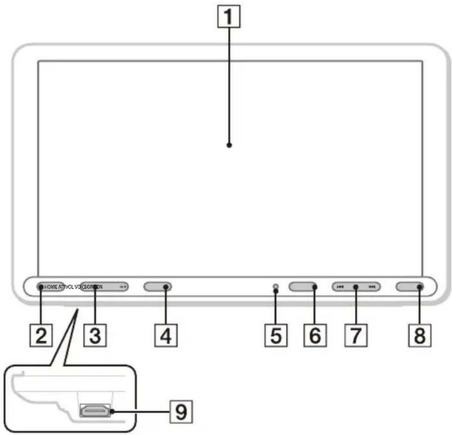
1 HOME AUDIO VOICE 2 3 4 5 6 7 8 9The VOL (volume) + button has a tactile dot.
1 Display/touch screen
2 HOME
Displays the HOME screen (page 5).
STANDBY
Press and hold to turn the unit to standby mode (USB charging is still available). To resume, press any button.
3 VOL (volume) +/-
4 ATT (attenuate)
Attenuates the sound.
To cancel, press again, or press VOL +.
MONITOR OFF
Press and hold to turn off the monitor.
To turn back on, touch any part of the display.
5 Reptor for the remote commander
6 OPTION
Displays the OPTION screen (page 5).
7 I◀◀ /▶▶ (previous/next)
Functions differently depending on the selected source:
- [Radio]/[DAB+]: select a preset station.
- [USB]/[Bluetooth]: move to the previous/next file.
Press and hold to:
- [Radio]: tune into a station automatically (SEEK+/SEEK-).
- [DAB+]: select a station (when [Seek By] is set to [A-Z])/search for a station (when [Seek By] is set to [Station Gp]).
- [USB]/[Bluetooth]: fast-reverse/fast-forward.
8 VOICE Activates the voice command function for Apple CarPlay and Android Auto™.
9 HDMI terminal (input)
Screen Displays
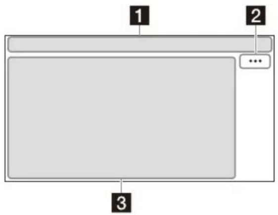
Playback screen:
text_image
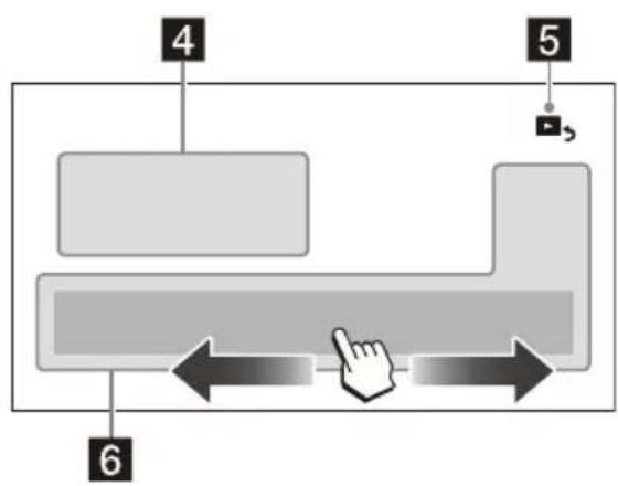
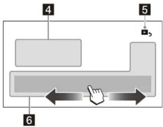
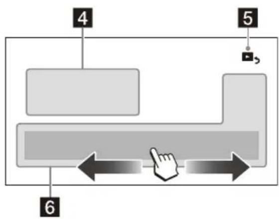
1 2 ... 3HOME screen:
flowchart
graph TD
    A["4"] --> B[" "]
    C["5"] --> D[" "]
    E["6"] --> F[" "]
    B --> G[" "]
    D --> H[" "]
    F --> I[" "]
    G --> J[" "]
    H --> K[" "]
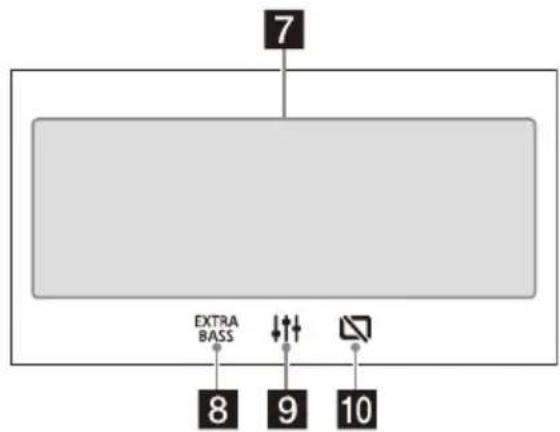
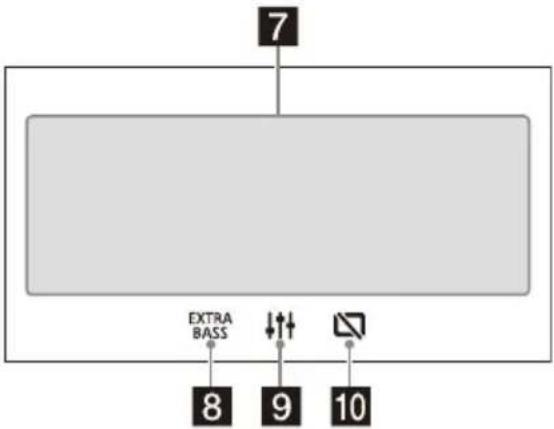
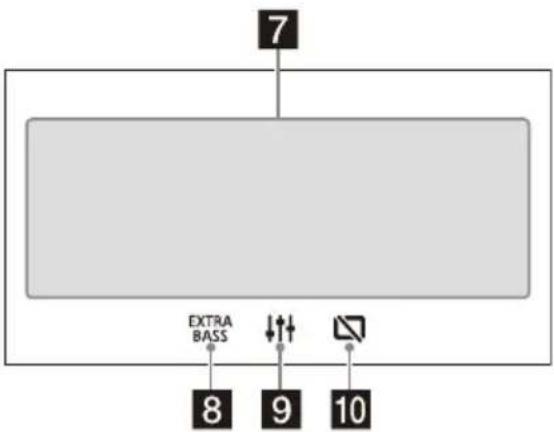
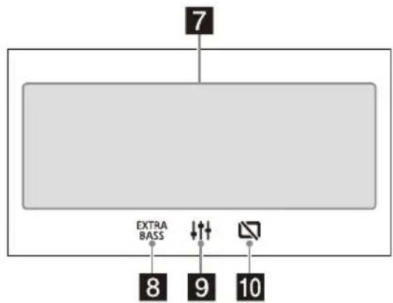
OPTION screen:

text_image
7 EXTRA BASS 8 9 101 Status indication
| ATT | Lights up when the sound is attenuated. |
| AF | Lights up when AF (Alternative Frequencies) is available. |
| TA | Lights up when the current traffic information (TA: Traffic Announcement) is available. |
| ANNC | Lights up when a DAB announcement is available. |
| DAB | Indicates the signal strength status of the DAB radio. |
| Lights up when the Bluetooth® signal is on. Flashes when the connection is in progress. | |
| Lights up when the audio device is playable by enabling the A2DP (Advanced Audio Distribution Profile). | |
| Lights up when handsfree calling is available by enabling the HFP (Handsfree Profile). | |
| Indicates the signal strength status of the connected mobile phone. | |
| Indicates the remaining battery status of the connected mobile phone. |
2 …(source option)
Opens the source option menu. The available items differ depending on the source.
3 Application specific area
Displays playback controls/indications or show the unit's status. Displayed items differ depending on the source.
4 Clock
Displays the time which are set on the Date/Time setting.
5 (return to the playback screen)
Switches from the HOME screen to the playback screen.
6 Sources and Settings select keys
Changes the source or make various settings. Flick to select the setting icon and other icons. Touch the source icon you want to select.
| [365X] | Android Auto | Apple CarPlay | Radio | ||
 | DAB+ Bluetooth Phone | ||||
 | USB WebLink HDMI | ||||
 | Rear Camera | Settings | |||
Sound select keys
Changes the sound.
8 EXTRA BASS(EXTRA BASS)
Changes the EXTRA BASS setting.
Changes the EQ10/Subwoofer setting.
10 monitor off)
Turns off the monitor. When the monitor is turned off, touch any part of the display to turn it back on.
Basic Operations
Pairing with a BLUETOOTH Device
When connecting a BLUETOOTH device for the first time, mutual registration (called "pairing") is required. Pairing enables this unit and other devices to recognize each other.
flowchart
graph LR
    A["Mobile Phone"] --> B["X"]
    B --> C["Monitor Screen"]
1 Press HOME, then touch [Settings] → [Bluetooth] → [Bluetooth Connection] → [ON] → [Pairing].
flashes while the unit is in pairing standby mode.
2 Perform pairing on the BLUETOOTH device so it detects this unit.
3 Select your model name shown on the display of the BLUETOOTH device*. When pairing is made, 8stays lit.
* If passkey input is required on the BLUETOOTH device, input [0000].
Connecting Rear View Camera
By connecting the optional rear view camera to the CAMERA IN terminal, you can display the picture from the rear view camera. For details, see "Connection/Installation" (page 10).
To display the picture from the rear view camera
Press HOME, then touch [Rear Camera].
Canceling the Demonstration Mode
1 Press HOME, then touch [Settings].
2 Touch [General], then touch [Demo] to set to [OFF].
3 To exit the setup menu, touch (back) twice.
Updating the Firmware
To update the firmware, visit the support site, then follow the online instructions.
URL: https://www.sony.eu/support
Note
During the update, do not remove the USB device.
Additional Information
Precautions
•Power antenna (aerial) extends automatically.
- When you transfer ownership or dispose of your car with the unit installed, initialize all the settings to the factory settings by performing the factory reset.
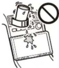
- Do not splash liquid onto the unit.
Notes on safety
- Comply with your local traffic rules, laws, and regulations.
- While driving
- Do not watch or operate the unit, as it may lead to distraction and cause an accident. Park your car in a safe place to watch or operate the unit.
- Do not use the setup feature or any other function which could divert your attention from the road.
- When backing up your car, be sure to look back and watch the surroundings carefully for your safety even if the rear view camera is connected. Do not depend on the rear view camera exclusively.
- While operating
- Do not insert your hands, fingers, or foreign objects into the unit as it may cause injury or damage to the unit.
- Keep small articles out of the reach of children.
- Be sure to fasten seatbelts to avoid injury in the event of sudden movement of the car.
Preventing an accident
Pictures appear only after you park the car and set the parking brake.
If the car starts moving during video playback, the following caution is displayed and you cannot watch the video.
[Video blocked for your safety.]
Do not operate the unit or watch the monitor while driving.
Notes on LCD panel
- Do not get the LCD panel wet or expose it to liquids. This may cause a malfunction.
- Do not press down hard on the LCD panel as doing so can distort the picture or cause a malfunction (i.e., the picture may become unclear or the LCD panel may be damaged).
- Do not touch the panel with objects other than with your finger as it may damage or break the LCD panel.
- Clean the LCD panel with a dry soft cloth. Do not use solvents such as benzine, thinner, commercially available cleaners, or antistatic spray.
- Do not use the unit outside the temperature range 0^ to 40^ (32°F to 104°F).
- If your car was parked in a cold or hot place, the picture may not be clear. However, the monitor is not damaged and the picture will become clear after the temperature in your car becomes normal.
- Some stationary blue, red, or green dots may appear on the monitor. These are called "bright spots" and can happen with any LCD. The LCD panel is precision-manufactured with more than 99.99% of its segments functional. However, it is possible that a small percentage (typically 0.01% ) of the segments may not light up properly. This will not, however, interfere with your viewing.
Notes on the touch screen
- This unit uses a resistive touch screen. Touch the screen directly with your fingertip.
- Multi-touch operation is not supported on this unit.
- Do not touch the screen with sharp objects such as a needle, pen, or fingernail. Operation with a stylus is not supported on this unit.
- Do not let any objects contact the touch screen. If the screen is touched by an object other than your fingertip, the unit may not respond correctly.
- Since glass material is used for the screen, do not subject the unit to strong shock. If cracking or chipping occurs on the screen, do not touch the damaged part as it may cause injury.
- Keep other electrical devices away from the touch screen. They may cause the touch screen to malfunction.
text_image
Illustration showing a book with a cup and a bottle, emitting exhaust smoke, and a no-smoking symbol above.About iPhone
•Compatible iPhone models:
iPhone SE (2nd generation), iPhone 11 Pro Max, iPhone 11 Pro, iPhone 11, iPhone XS Max, iPhone XS, iPhone XR, iPhone X, iPhone 8 Plus, iPhone 8, iPhone 7 Plus, iPhone 7, iPhone SE, iPhone 6s Plus, iPhone 6s, iPhone 6 Plus, iPhone 6, iPhone 5s
- Use of the Made for Apple badge means that an accessory has been designed to connect specifically to the Apple product(s) identified in the badge, and has been certified by the developer to meet Apple performance standards. Apple is not responsible for the operation of this device or its compliance with safety and regulatory standards. Please note that the use of this accessory with an Apple product may affect wireless performance.
Notice on license
This product contains software that Sony uses under a licensing agreement with the owner of its copyright. We are obligated to announce the contents of the agreement to customers under requirement by the owner of copyright for the software.
For details on software licenses, select [Settings] → [General] → [Open Source Licenses].
If you have any questions or problems concerning your unit that are not covered in this Operating Instructions, consult your nearest Sony dealer.
Specifications
Monitor section
Display type: Wide LCD color monitor
Dimensions: 8.95 in/227 mm
System: TFT active matrix
Number of pixels:
1,152,000 pixels (800 × 3 (RGB) × 480)
Color system:
PAL/NTSC automatic select for CAMERA IN terminal
Radio section
DAB/DAB+
Tuning range: 174.928 MHz - 239.200 MHz
Antenna (aerial) terminal:
External antenna (aerial) connector
FM
Tuning range: 87.5 MHz - 108.0 MHz
Usable sensitivity: 7 dBf
Signal-to-noise ratio: 70 dB (mono)
Separation at 1 kHz: 45 dB
AM
Tuning range: 531 kHz - 1,602 kHz
Sensitivity: 32 μV
USB player section
Interface:
USB port: USB (Hi-speed)
Maximum current: 1.5 A
HDMI section\*
Input format: 480p, 576p, 720p
* HDMI output is not available.
Wireless communication
Communication System:
BLUETOOTH Standard version 3.0
Output:
BLUETOOTH Standard Power Class 2
(Max. Conducted +1 dBm)
Maximum communication range ^*1 :
Line of sight approx. 10 m (33 ft)
Frequency band:
2.4 GHz band (2.4000 GHz - 2.4835 GHz)
Modulation method: FHSS
Compatible BLUETOOTH Profiles ^2 :
A2DP (Advanced Audio Distribution Profile) 1.3
AVRCP (Audio Video Remote Control Profile) 1.3
HFP (Handsfree Profile) 1.6
PBAP (Phone Book Access Profile) 1.1
Corresponding codec: SBC, AAC
*1 The actual range will vary depending on factors such as obstacles between devices, magnetic fields around a microwave oven, static electricity, reception sensitivity, antenna (aerial) performance, operating system, software application, etc.
*2 BLUETOOTH standard profiles indicate the purpose of BLUETOOTH communication between devices.
Power amplifier section
Outputs: Speaker outputs
Speaker impedance: 4 Ω – 8 Ω
Maximum power output: 55 W × 4 (at 4 Ω)
General
Power requirements: 12 V DC car battery (negative ground (earth))
Rated current consumption: 10 A
Dimensions (maximum):
Approx. 229 mm × 136 mm × 253 mm
(9 1/8 in × 5 3/8 in × 10 in) (w/h/d)
Mounting dimensions:
Approx. 182 mm × 53 mm × 160 mm
(7 1/4 in × 2 1/8 in × 6 3/8 in) (w/h/d)
Mass: Approx. 2.4 kg (5 lb 5 oz)
Package contents:
Main unit (1)
Parts for installation and connections (1 set)
Ask the dealer for detailed information.
Design and specifications are subject to change without notice.
Copyrights
The Bluetooth ^® word mark and logos are registered trademarks owned by Bluetooth SIG, Inc. and any use of such marks by Sony Corporation is under license. Other trademarks and trade names are those of their respective owners.
Windows Media is either a registered trademark or trademark of Microsoft Corporation in the United States and/or other countries.
This product is protected by certain intellectual property rights of Microsoft Corporation. Use or distribution of such technology outside of this product is prohibited without a license from Microsoft or an authorized Microsoft subsidiary.
Apple and iPhone are trademarks of Apple Inc., registered in the U.S. and other countries. Apple CarPlay is a trademark of Apple Inc.
Android Auto is a trademark of Google LLC.
WebLink is a registered trademark of Abalta Technologies, Inc. in the U.S. and a trademark in the other countries.
The terms HDMI, HDMI High-Definition Multimedia Interface, and the HDMI Logo are trademarks or registered trademarks of HDMI Licensing Administrator, Inc.
All other trademarks are trademarks of their respective owners.
Connection/Installation
Cautions
- Do not install this unit in a car that has no ACC position. The display of the unit does not turn off even after turning the ignition off, and this causes battery drain.
- Run all ground (earth) leads to a common ground (earth) point.
- Do not get the leads trapped under a screw or caught in moving parts (e.g., seat railing).
- Before making connections, turn the car ignition off to avoid short circuits.
- Connect the power supply leads ① to the unit and speakers before connecting it to the auxiliary power connector.
- Be sure to insulate any loose unconnected leads with electrical tape for safety.
- Choose the installation location carefully so that the unit will not interfere with normal driving operations.
- Avoid installing the unit in areas subject to dust, dirt, excessive vibration, or high temperature, such as in direct sunlight or near heater ducts.
- Use only the supplied mounting hardware for a safe and secure installation.
- Be sure to use the supplied USB extension cables.
- This unit may not be installed properly depending on the car type. For details on the mounting space, see "Ensuring the mounting location of the unit" (page 10).
- To avoid injury, be careful not to drop the display during installation.
- When installing, be careful not to cut off your fingers with the metal parts of the brackets and mounting base.
- Do not pinch your fingers when attaching the display to the unit.
- Do not install the unit in a position where the unit interferes with driving operations (such as in positions where the shift lever hits the unit, or the hazard button cannot be pressed).
- When using the unit for a long period of time, there may be a possibility that the screws securing the display may come loose. Periodically tighten these screws.
- Do not make any changes or modifications to the unit other than those described in this manual.
Note on the power supply lead (yellow)
When connecting this unit in combination with other stereo components, the amperage rating of the car circuit to which the unit is connected must be higher than the sum of each component's fuse amperage rating.
Note on installing in cars with a start-stop system
The unit may restart when starting the engine from start-stop. In this case, turn off the start-stop system of your car.
Note on installing in cars with electric parking brake system
For cars with electric parking brakes, some related functions (such as video blocking function) may not work properly.
Mounting angle adjustment
Adjust the mounting angle to less than 30^ .
Ensuring the mounting location of the unit
Before installing the unit, consult the installer for details on the installation of the unit and the display.
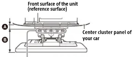
- Make sure that the distance from the front surface (reference surface) of the mounted unit to the surface of your car's center cluster is within 22 mm (7/8 in). If exceeded, the unit cannot be installed properly.
text_image
Front surface of the unit (reference surface) Center cluster panel of your carScrew hole positions
(for securing the display and the unit)
A 22 mm (7/8 in) B 51 mm to 71 mm (2½ in to 2 7/8 in)
- For your safety, adjust the mounting location of the unit so that it does not interfere with driving operations such as button (switch) or shift lever operations.
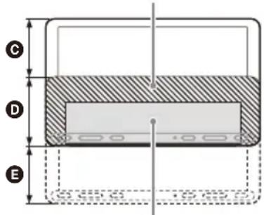
Hidden area even when the display is slid up or down
text_image
C D EPosition of the unit (reference position)
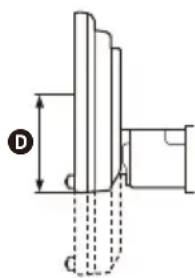
text_image
D GC 60 mm (2 3/8 in) D 76 mm (3 in) E 60 mm (2 3/8 in)
Parts List for Installation
① Power supply leads (1)
② Mounting screw (5 × max. 9 mm (7/32 × max. 3/8 in)) (4)
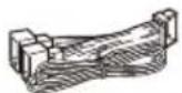

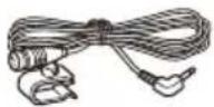
③ Microphone (1)
④ Flat-mount base (1)
⑤ Double-sided tape (1)
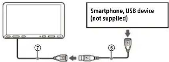
⑥ USB extension cable (long) (1)


⑦ USB extension cable (short) (1)
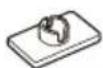
⑧ Cable tie (1)


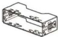
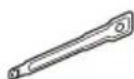
⑨ Mounting sleeve (1) ⑩ Release keys (2)
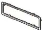
⑪ Trim ring (1)
⑫ Rear panel cover (left/right) (2)

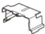
⑬ Jointaver (1)
⑭ Fixing screw (for the joint cover) (3 × 8 mm (1/8 × 11/32 in)) (1)

⑮ Fixing screw (for the joint part) (4 × 6 mm (3/16 × 1/4 in)) (4)

- This parts list does not include all the package contents.
- The mounting sleeve ⑨ is attached to the unit before shipping. Before mounting the unit, use the release keys ⑩ to remove the mounting sleeve ⑨ from the unit. For details, see "① Removing the trim ring and the mounting sleeve" (page 15).
- Keep the release keys ⑩ for future use as they are also necessary if you remove the unit from your car.
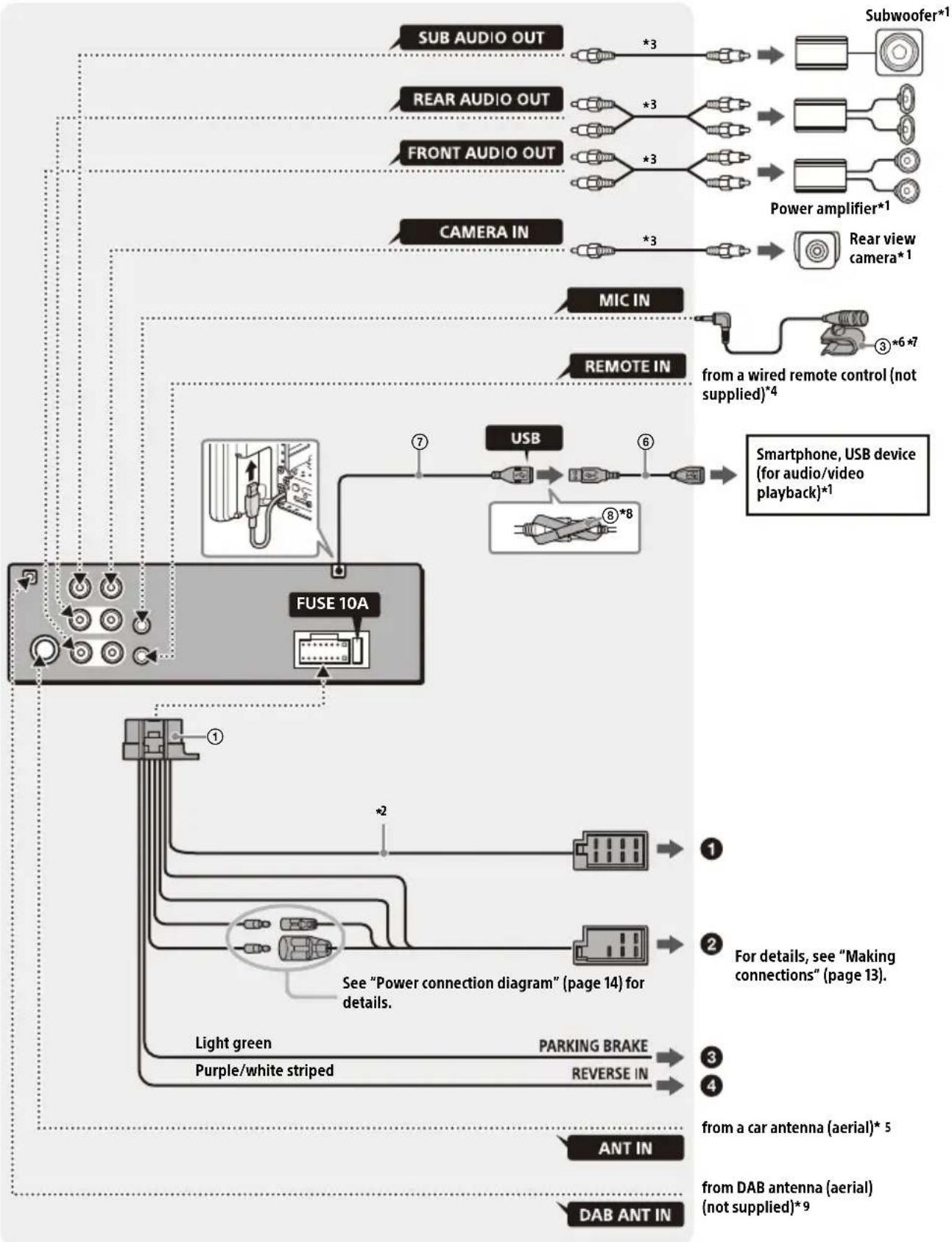
Connection
• To prevent short circuits, insulate leads with a cover or tape.
- Note that the unit may be damaged if it is connected incorrectly or by short circuits.
flowchart
graph TD
    A["SUB AUDIO OUT"] --> B["*3"]
    C["REAR AUDIO OUT"] --> D["*3"]
    E["FRONT AUDIO OUT"] --> F["*3"]
    G["CAMERA IN"] --> H["*3"]
    I["MIC IN"] --> J["from a wired remote control (not supplied)*4"]
    K["REMOTE IN"] --> L["from a wired remote control (not supplied)*4"]
    M["USB"] --> N["Smartphone, USB device (for audio/video playback)*1"]
    O["FUSE 10A"] --> P["*2"]
    Q["Light green"] --> R["Parking Brake"]
    S["Purple/white striped"] --> T["Reverse IN"]
    U["ANT IN"] --> V["from a car antenna (aerial)*5"]
    W["DAB ANT IN"] --> X["from DAB antenna (aerial) (not supplied)*9"]
    style A fill:#f9f,stroke:#333
    style C fill:#f9f,stroke:#333
    style E fill:#f9f,stroke:#333
    style G fill:#f9f,stroke:#333
    style I fill:#f9f,stroke:#333
    style K fill:#f9f,stroke:#333
    style M fill:#f9f,stroke:#333
    style O fill:#f9f,stroke:#333
    style Q fill:#f9f,stroke:#333
    style U fill:#f9f,stroke:#333
*1 Not supplied
*2 Speaker impedance: 4 Ω to 8 Ω × 4
*3 RCA pin cord (not supplied)
*4 Depending on the type of car, use an adaptor for a wired remote control (not supplied). For details on using the wired remote control, see "Using the wired remote control" (page 14).
*5 Depending on the type of car, use an adaptor (not supplied) if the antenna (aerial) connector does not fit.
*6 Whether in use or not, route the microphone input cord so it does not interfere with driving operations. Secure the cord with a clamp, etc., if it is installed around your feet.
*7 For details on installing the microphone, see "Installing the microphone" (page 14).
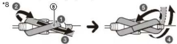
flowchart
graph TD
    A["Step 1: Initial state"] --> B["Step 2: Rotation arrow"]
    B --> C["Step 3: Rolling loop"]
    C --> D["Step 4: Rotation arrow"]
    D --> E["Step 5: Rotation arrow"]
    E --> F["Step 6: Rotation arrow"]
    F --> G["Step 7: Rotation arrow"]
    G --> H["Step 8: Rotation arrow"]
    H --> I["*8"]
*9 Set [Antenna Power] to [ON] (default) or [OFF] depending on the type of DAB antenna (aerial) (not supplied). Max. supply current 0.1 A
Making connections
If you have a power antenna (aerial) without a relay box, connecting this unit with the power supply leads ① may damage the antenna (aerial).
① To the car's speaker connector
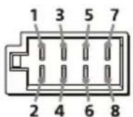
| 1 | Rear speaker(right) | ⊕ | Purple |
| 2 ⊕ | Purple/blackstriped | ||
| 3 | Front speaker(right)/black striped | ⊕ | Gray |
| 4 ⊕ | |||
| 5 | Front speaker(left) | ⊕ | White |
| 6 ⊕ | White/blackstriped | ||
| 7 | Rear speaker(left) | ⊕ | Green |
| 8 ⊕ | Green/blackstriped |
② To the car's power connector
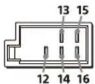
| 12 | continuous power supply | Yellow |
| 13 | power antenna (aerial) / power amplifier control (REM OUT) | Blue/white striped |
| 14 | switched illumination power supply | Orange/white striped |
| 15 | switched power supply Red | |
| 16 | ground (earth) Black |
③ To the parking brake switch lead
The mounting position of the parking brake switch lead depends on your car. Be sure to connect the parking brake lead (light green) of the power supply leads ① to the parking brake switch lead.
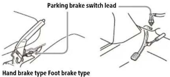
text_image
Parking brake switch lead Hand brake type Foot brake type4 d the +12 V power terminal of the car's rear lamp lead (only when connecting the rear view camera)
Memory hold connection
When the yellow power supply lead is connected, power will always be supplied to the memory circuit even when the ignition switch is turned off.
Speaker connection
- Before connecting the speakers, turn the unit off.
- Use speakers with an impedance of 4 to 8 , and with adequate power handling capacities to avoid damage.
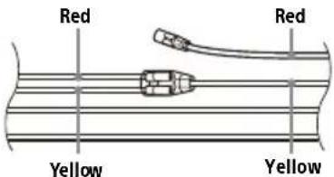
Power connection diagram
Check your car's auxiliary power connector, and match the connections of leads correctly depending on the car.
Auxiliary power connector
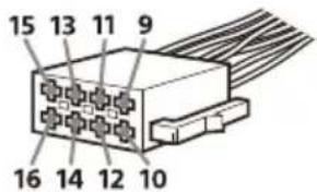
text_image
15 13 11 9 16 14 12 10Common connection
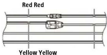
text_image
Red Red Yellow Yellow| 12 | continuous power supply | Yellow |
| 15 s | switched power supply Red |
When the positions of the red and yellow leads are inverted
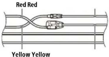
text_image
Red Red Yellow Yellow| 12 | switched power supply Yellow | |
| 15 | continuous powersupply | Red |
When the car without ACC position
text_image
Red Red Yellow YellowAfter matching the connections and switching power supply leads correctly, connect the unit to the car's power supply. If you have any questions and problems connecting your unit that are not covered in this manual, consult the car dealer.
Installing the microphone
To capture your voice during handsfree calling, you need to install the microphone ③.
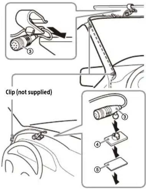
text_image
Clip (not supplied)Cautions
- It is extremely dangerous if the cord becomes wound around the steering column or gearstick. Be sure to keep it and other parts from interfering with your driving operations.
- If airbags or any other shock-absorbing equipment are in your car, contact the store where you purchased this unit or the car dealer before installation.
Notes
- When mounting on the dashboard, remove the visor clip carefully from the microphone ③, then attach the flat-mount base ④ to the microphone ③.
- Before attaching the double-sided tape ⑤, clean the surface of the dashboard with a dry cloth.
Using the wired remote control
1 To enable the wired remote control, set [Steering Control] in [General] to [Preset].
Using the rear view camera
Installation of the rear view camera (not supplied) is required before use.
The picture from a rear view camera connected to the CAMERA IN terminal is displayed when:
- the back lamp of your car lights up (or the shift lever is set to the R (reverse) position).
- you press HOME, then touch [Rear Camera].
Installation
To install the unit and the display securely, be sure to follow the steps ① to ⑧ in order.
① Removing the trim ring and the mounting sleeve (page 15)
② Before mounting the unit (page 15)
③ Mounting the unit in the dashboard (page 16)
4 Attaching the joint cover (page 16)
⑤ Setting up the display (page 16)
⑥ Making sure the mounting positions of the display (page 18)
⑦ Organizing the USB cable (page 18)
8 Attaching the display to the unit (page 18)
For your safety
After mounting the display to the unit, make sure that the display does not interfere with normal driving operations such as blocking the driver's view or getting the cables tangled.
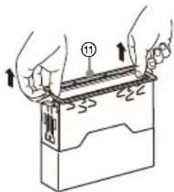
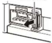
① Removing the trim ring and the mounting sleeve
Before installing the unit, remove the trim ring ⑪ and the mounting sleeve ⑨ from the unit.
1 Pinch both edges of the trim ring ⑪, then pull it out.
text_image
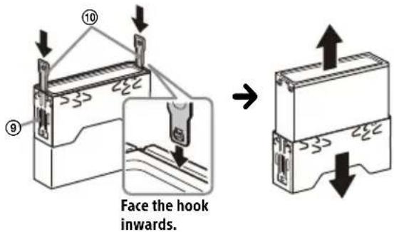
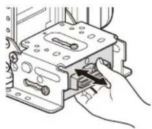
Diagram showing hands holding a device with numbered components and arrows indicating movement or assembly2 Insert both release keys ⑩ until they click, and pull down the mounting sleeve ⑨, then pull up the unit to separate.
text_image
Face the hook inwards.② Before mounting the unit
Before mounting the unit in the dashboard, arrange the USB extension cables.
USB cable connection diagram
flowchart
graph TD
    A["Computer monitor"] --> B["USB device"]
    B --> C["USB device (not supplied)"]
    C --> D["USB device"]
    style A fill:#f9f,stroke:#333
    style D fill:#bbf,stroke:#333
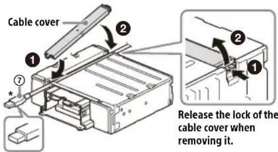
1 Remove the cable cover, store the USB extension cable (short) ⑦ to the groove of the unit, then attach the cable cover. Position the USB cable so that its connector (male) comes to the front side of the unit.
text_image
Cable cover ① ② ⑦ Release the lock of the cable cover when removing it.* USB connector (male)
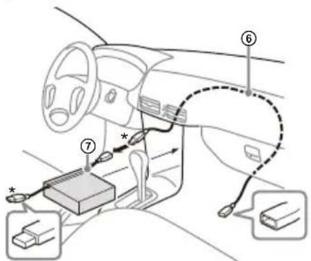
2 Route the USB extension cable (long) ⑥ inside the dashboard, then connect the USB cable (short) ⑦ from the unit.
Position the USB cable so that its connector (male) comes out from the center console panel.
text_image
Diagram of car interior showing labeled components including steering wheel, dashboard, and battery pack with connection points* USB connector (male)
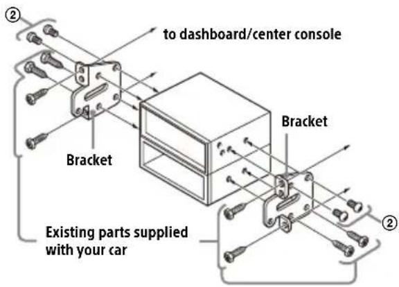
③ Mounting the unit in the dashboard
Using the mounting brackets supplied with your car
You may not be able to install this unit in some makes of Japanese cars. In such a case, consult your Sony dealer.
Example
text_image
to dashboard/center console Bracket Bracket Existing parts supplied with your carNote
To prevent malfunction, install only with the mounting screws ②.
4 Attaching the joint cover
1 Attach the joint cover ⑬ to the mounting base of the unit, then slide it into the unit temporarily.
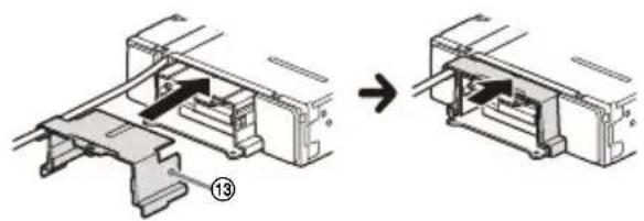
natural_image
Mechanical assembly diagram showing a bracket being inserted into a housing (no text or symbols present)⑤ Setting up the display
The mounting positions of the display can be adjusted.
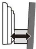
Depth
(within 20 mm
(13/16 in), in 3 steps)
Height
(within 60 mm
(2 3/8 in), in 7 steps)

Angle
(-10° to +10°, in 3
steps)
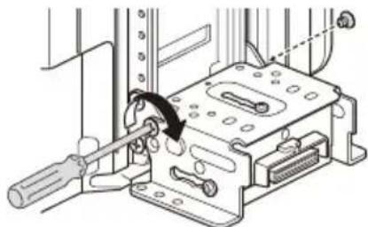
Adjusting the depth of the display position
1 Loosen the 3 pre-installed screws for depth adjustment (on top and both sides).
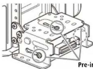
natural_image
Mechanical assembly diagram showing a device with labeled parts and a highlighted section (no readable text or symbols)Pre-installed screws
Slightly loosen the screws until you can slide the connector bracket. Do not remove the screws from the bracket. Doing so may damage the parts.
2 Slide the connector bracket to decide the appropriate depth position.
Adjustable depth: within 20 mm ( ^13/16 in) (A), in 3 steps, in 10 mm ( ^13/32 in) pitch (B).
natural_image
Hand inserting a component into a device housing (no text or symbols visible)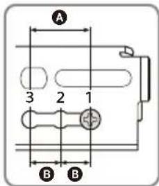
text_image
A 3 2 1 B BBracket positions 1 to 3 for the display:
1: Slide-out position
2: Intermediate position
3: Slide-in position
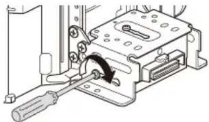
3 At the desired position, tighten the 3 screws firmly to secure the connector bracket.
natural_image
Mechanical assembly diagram showing a tool interacting with a device housing (no text or symbols visible)Tighten the screws firmly. When you tighten a screw, be careful not to apply too much torque as doing so may damage the screw (the torque value should be from 1.2 N•m to 1.5 N•m).
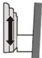
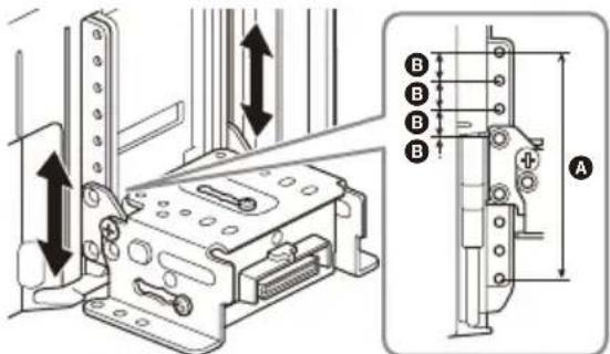
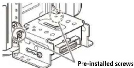
Adjusting the height of the display position
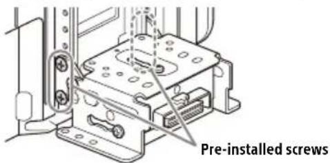
1 Remove the 4 pre-installed screws for height adjustment (on both sides).
text_image
Pre-installed screws2 Slide the connector bracket up or down to decide the appropriate height position. Adjustable height: within 60 mm (23/8 in) (A), in 7 steps, in 10 mm ( ^13/_32 in) pitch (B).
text_image
Technical diagram showing mechanical assembly with labeled parts and directional arrows indicating movement or force3 At the desired position, tighten the 4 screws firmly to secure the connector bracket.
natural_image
Technical diagram of a mechanical assembly with a tool and bracket (no text or symbols visible)Tighten the screws firmly. When you tighten a screw, be careful not to apply too much torque as doing so may damage the screw (the torque value should be from 1.2 N•m to 1.5 N•m).
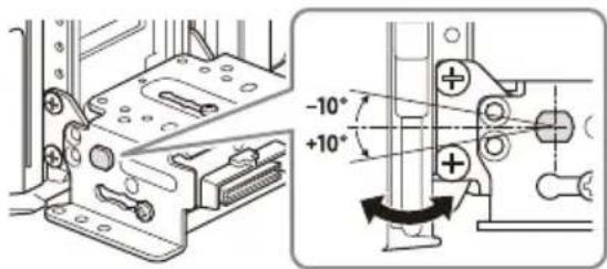
Adjusting the display angle (tilt)
1 Remove the 2 pre-installed screws for angle adjustment (on both sides).
text_image
Pre-installed screws2 Adjust the display angle to decide the appropriate angle.
Adjustable angle: -10^ to +10^ , in 3 steps
text_image
Technical diagram showing mechanical assembly with 10° angle annotations and directional arrows indicating movement or force.Screw holes to use:
$$ 0 ^ {\circ} (1 - A) - 1 0 ^ {\circ} (3 - B) + 1 0 ^ {\circ} (2 - B) $$
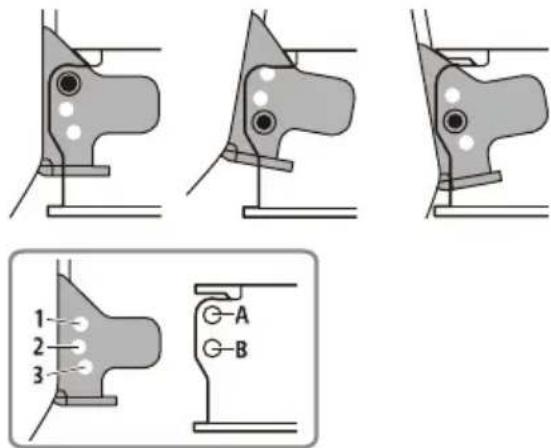
text_image
1 2 3 A B3 At the desired angle, tighten the 2 screws through the screw holes (upper or lower) that match the display angle.
natural_image
Mechanical assembly diagram showing a tool inserted into a housing with a screwdriver, no text or symbols presentTighten the screws firmly. When you tighten a screw, be careful not to apply too much torque as doing so may damage the screw (the torque value should be from 1.2 N•m to 1.5 N•m).
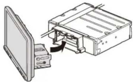
⑥ Making sure the mounting positions of the display
Be careful not to pinch your fingers or scratch the center cluster panel of your car when attaching the display to the unit.
1 Attach the display to the unit temporarily.
natural_image
Diagram of a computer interface showing a monitor connected to an internal device with a cable, no text or symbols present.2 Confirm that the display does not block the driver's view or interfere with normal driving operations.
If further adjustment of the mounting position (depth, height, angle) is necessary, remove the display from the unit, then adjust it again accordingly.
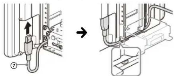
⑦ Organizing the USB cable
1 Connect the USB extension cable (short) ⑦ to the USB port of the display, then route the cable along the groove.
text_image
Technical diagram showing cable installation and connection to a device, with numbered components and directional arrow indicating process.To prevent the extension cable from coming off, be sure to route the USB cable along the groove through the catches inside.
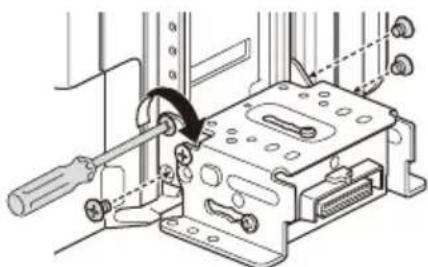
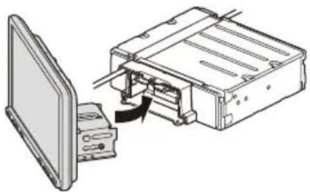
8 Attaching the display to the unit
Be careful not to pinch your fingers or scratch the center cluster panel of your car when attaching the display to the unit.
1 Attach the display to the unit.
natural_image
Diagram of a computer monitor and its internal components, showing a close-up assembly (no text or symbols)Make sure that the connector brackets of the display is fully inserted to the unit.
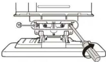
2 Tighten 4 screws ⑮ (on top) to secure the connector bracket to the unit.
text_image
⑮Tighten the screws firmly.
When you tighten a screw, be careful not to apply too much torque as doing so may damage the screw (the torque value should be from 1.2 N•m to 1.5 N•m).
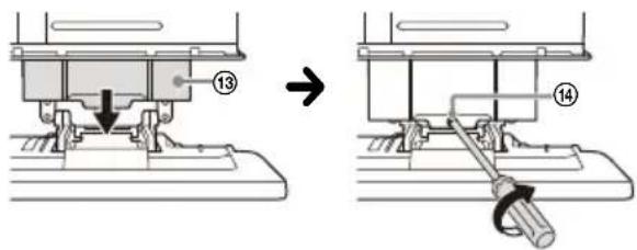
3 Slide the joint cover ⑬ out to protect the mounting base of the display, then tighten the fixing screw ⑭ to secure the cover.
text_image
Technical diagram showing mechanical assembly steps with numbered components and directional arrows indicating motionTighten the screw firmly.
When you tighten a screw, be careful not to apply too much torque as doing so may damage the screw (the torque value should be from 1.2 N•m to 1.5 N•m).
4 Attach the rear panel covers (L, R) ⑫ along the guides for protection.
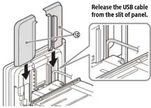
text_image
Release the USB cable from the slit of panel.Fuse replacement
When replacing the fuse, be sure to use one matching the amperage rating stated on the original fuse. If the fuse blows, check the power connection and replace the fuse. If the fuse blows again after replacement, there may be an internal malfunction. In such a case, consult your nearest Sony dealer.
Fuse (10 A)
Avertissement
text_image
1 2 ... 3Écran HOME :
flowchart
graph TD
    A["4"] --> B[" "]
    C["5"] --> D[" "]
    E["6"] --> F[" "]
    G["Arrow with cursor"] --> H["Arrow with arrow"]
    style A fill:#ccc,stroke:#333
    style C fill:#ccc,stroke:#333
    style E fill:#ccc,stroke:#333
    style G fill:#ccc,stroke:#333
Écran OPTION :
text_image
7 EXTRA BASS 8 9 10flowchart
graph LR
    A["Mobile Device"] --> B["X-Simulus Connection"]
    B --> C["Monitor Screen"]
text_image
Illustration showing a coffee maker with a coffee cup and a prohibition symbol, indicating a food safety or disinfection scenario.174,928 MHz - 239,200 MHz
Borne d'antenne :
Norme BLUETOOTH version 3.0
Puissance :
Dimensions (maximum):
Environ 229 mm × 136 mm × 253 mm (l/h/p)
Appareil principal (1)
Raccordement/Installation
Attention
text_image
*8 ② ⑧ ① ③ → ⑤ ④natural_image
Technical line drawings showing mechanical assembly steps (no text or symbols)text_image
Clip (non fourni)Attention
text_image
Diagram showing hands operating a device with labeled components and directional arrows indicating movement or assembly.text_image
Diagram of car interior showing labeled components including steering wheel, dashboard, and battery pack with connection pointsnatural_image
Mechanical assembly diagram showing a component being processed into a housing (no text or symbols present)natural_image
Mechanical assembly diagram showing a device with labeled parts and a 'Vis pr' annotation (no readable text or symbols beyond label)Vis pré-installées
natural_image
Illustration of a hand inserting a component into a device housing (no text or symbols visible)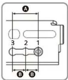
text_image
A 3 2 1 B Bnatural_image
Technical line drawing of a mechanical assembly with a tool inserted, showing no text or symbols.text_image
Technical diagram showing mechanical assembly with labeled components and directional arrows indicating movement or forcenatural_image
Mechanical assembly diagram showing a lever mechanism interacting with a component (no text or symbols visible)text_image
-10° +10°natural_image
Three diagrams showing mechanical joint configurations with no visible text or symbols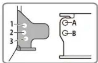
text_image
1 2 3 G-A G-Bnatural_image
Mechanical assembly diagram showing a lever mechanism with no visible text or symbolsnatural_image
Diagram of a computer interface showing an open monitor and internal components with a cable being inserted (no text or symbols present)text_image
Technical diagram showing cable installation steps with labeled components and directional arrownatural_image
Diagram of a computer device showing an open panel connected to a rectangular box with a cable, no text or symbols present.text_image
Technical diagram of a mechanical assembly with numbered component 15 labeledtext_image
Technical diagram showing mechanical assembly steps with numbered components and directional arrowtext_image
1 2 ... 3HOME-Bildschirm:

flowchart
graph TD
    A["4"] --> B[" "]
    C["5"] --> D[" "]
    E["6"] --> F[" "]
    B --> G[" "]
    D --> H[" "]
    F --> I[" "]
    G --> J[" "]
    H --> K[" "]
OPTION-Bildschirm:
text_image
7 EXTRA BASS 8 9 101 Statusanzeige
text_image
Illustration showing a hand holding a megaphone with a stop sign, indicating no chemical reaction or pollution.A2DP (Advanced Audio Distribution Profile) 1.3
AVRCP (Audio Video Remote Control Profile) 1.3 HFP (Handsfree Profile) 1.6
PBAP (Phone Book Access Profile) 1.1
© 60 mm D 76 mm E 60 mm
flowchart
graph TD
    A["1: Folded Ring"] --> B["2: Disformed Ring"]
    B --> C["3: Folded Ring"]
    C --> D["4: Disformed Ring"]
    D --> E["5: Folded Ring"]
    E --> F["6: Disformed Ring"]
    style A fill:#f9f,stroke:#333
    style F fill:#bbf,stroke:#333
natural_image
Illustration of hands holding a rectangular device with internal components and arrows indicating motion (no text or symbols)text_image
Diagram of car interior showing labeled components including steering wheel, dashboard, and battery pack with connection points*USB-Stecker
text_image
Technical diagram showing mechanical assembly transformation with labeled component 13natural_image
Mechanical assembly diagram showing a component with mounting holes and a highlighted section (no text or symbols)natural_image
Illustration of a hand inserting a device into a rack (no text or symbols visible)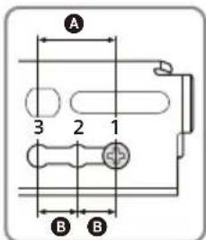
text_image
A 3 2 1 B Bnatural_image
Mechanical assembly diagram showing a screwdriver inserted into a housing component with a curved arrow indicating motion (no text or symbols present)natural_image
Technical diagram of a mechanical assembly with mounting brackets and a central housing (no text or symbols visible)text_image
Technical diagram showing mechanical assembly with labeled components and directional arrows indicating movement or forcenatural_image
Technical line drawing of a mechanical assembly with no visible text or symbolstext_image
-10° +10°natural_image
Three diagrams showing mechanical joint configurations with no visible text or symbols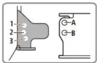
text_image
1 2 3 A Bnatural_image
Mechanical assembly diagram showing a lever mechanism with no visible text or symbolsnatural_image
Diagram showing a computer monitor connected to an internal device with a cable, no text or symbols presenttext_image
Technical diagram showing cable installation steps with labeled components and directional arrownatural_image
Diagram of a computer interface showing an open panel connected to a rectangular device with a cable or connector (no text or symbols visible)natural_image
Mechanical assembly diagram showing a lever mechanism with no visible text or symbolstext_image
Technical diagram showing mechanical assembly steps with numbered components and directional arrowhttps://compliance.sony.eu

text_image
1 2 ... 3Pantalla HOME:

flowchart
graph TD
    A["4"] --> B[" "]
    C["5"] --> D[" "]
    E["6"] --> F[" "]
    B --> G[" "]
    D --> H[" "]
    F --> I[" "]
    G --> J[" "]
    H --> K[" "]
Pantalla OPTION:
text_image
7 EXTRA BASS 8 9 10flowchart
graph LR
    A["Mobile Phone"] --> B["X-shaped Arrow"]
    B --> C["Device with Screen Icon"]
1 Pulse HOME y, a continuación, toque [Ajustes] → [Bluetooth] → [Conexión Bluetooth] → [ACTIV.] → [Conectar].
URL: https://www.sony.eu/support
Nota
text_image
Illustration showing a coffee maker with a coffee cup and a prohibition symbol, indicating a food safety or disinfection scenario.174,928 MHz - 239,200 MHz
Terminal de antena:
Conector de antena externa
FM
© 60 mm D 76 mm E 60 mm
text_image
*8 ② ⑧ ① ③ → ⑤ ④text_image
Diagram showing hands operating a device with numbered components and directional arrows indicating movement or assembly.text_image
Diagram of car interior showing connected components with numbered labels and connection arrows* Conector USB (macho)
natural_image
Mechanical assembly diagram showing a component being processed into a housing (no text or symbols present)natural_image
Illustration of a hand inserting a component into a device housing (no text or symbols visible)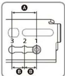
text_image
A 3 2 1 B Bnatural_image
Mechanical assembly diagram showing a tool inserted into a housing with a screwdriver inserted (no text or symbols visible)text_image
Technical diagram showing mechanical assembly with labeled components and directional arrows indicating movement or forcenatural_image
Technical line drawing of a mechanical assembly with no visible text or symbolstext_image
-10° +10°text_image
1 2 3 G-A G-Bnatural_image
Mechanical assembly diagram showing a tool inserted into a housing with a screwdriver (no text or symbols visible)natural_image
Diagram showing a computer monitor connected to an electronic device with a cable, no text or symbols presenttext_image
Technical diagram showing cable installation steps with labeled components and directional arrownatural_image
Diagram of a computer monitor connected to an internal device via cable, showing no text or symbolsnatural_image
Technical line drawing of a mechanical assembly with no visible text or symbolstext_image
Technical diagram showing mechanical assembly steps with numbered components and directional arrows indicating motiontext_image
1 2 ... 3HOME-scherm:

flowchart
graph TD
    A["4"] --> B[" "]
    C["5"] --> D[" "]
    E["6"] --> F[" "]
    B --> G[" "]
    D --> H[" "]
    F --> I[" "]
    G --> J[" "]
    H --> K[" "]
OPTION-scherm:

text_image
7 EXTRA BASS 8 9 101 Statusaanduiding
flowchart
graph LR
    A["Mobile Phone"] --> B["X"]
    B --> C["Monitor Screen"]
URL: https://www.sony.eu/support
Opmerking
[Video blocked for your safety.]
text_image
Safety warning illustration showing a hand holding a megaphone and a stop sign, with text indicating no hazard or caution.Opmerking over licenties
A2DP (Advanced Audio Distribution Profile) 1.3
AVRCP (Audio Video Remote Control Profile) 1.3 HFP (Handsfree Profile) 1.6
PBAP (Phone Book Access Profile) 1.1
Overeenkomstige codec: SBC, AAC
© 60 mm D 76 mm E 60 mm
text_image
*8 ② ⑧ ① ③ → ⑤ ④text_image
Diagram showing hands holding a device with numbered parts and directional arrows indicating movement or assembly.text_image
Diagram of car interior showing labeled components including steering wheel, battery pack, and cable routingnatural_image
Mechanical assembly diagram showing a bracket being inserted into a housing, with no visible text or symbolsnatural_image
Mechanical assembly diagram showing a housing with mounting holes and a close-up of a component (no text or symbols visible)natural_image
Illustration of a hand inserting a device into a device housing (no text or symbols visible)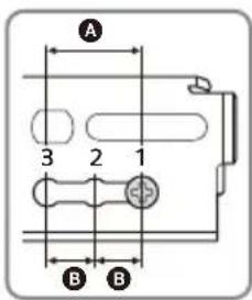
text_image
A 3 2 1 B Bnatural_image
Technical line drawing of a mechanical assembly with a screwdriver inserted (no text or symbols)natural_image
Mechanical assembly diagram showing a housing component with mounting holes and a labeled part 'Voorge' (no readable text or symbols beyond label)text_image
Technical diagram showing mechanical assembly with labeled components and directional arrows indicating movement or forcenatural_image
Mechanical assembly diagram showing a lever mechanism interacting with a housing component (no text or symbols visible)text_image
Technical diagram showing mechanical assembly with 10° angle annotations and directional arrows indicating motion or force vectors.natural_image
Three sequential diagrams showing mechanical joint configurations with circular holes, no text or symbols present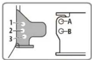
text_image
1 2 3 G-A G-Bnatural_image
Mechanical assembly diagram showing a tool inserted into a housing component with a curved arrow indicating rotation (no text or symbols present)natural_image
Diagram showing a computer monitor connected to an internal device with a cable, no text or symbols presenttext_image
Technical diagram showing cable installation steps with labeled components and directional arrownatural_image
Diagram showing a computer monitor connected to an internal device with cable, no text or symbols presentnatural_image
Technical line drawing of a mechanical assembly with no visible text or symbolstext_image
Technical diagram showing mechanical assembly steps with numbered components and directional arrows indicating motiontext_image
1 2 ... 3HOME-skärm:
flowchart
graph TD
    A["4"] --> B[" "]
    C["5"] --> D[" "]
    E["6"] --> F[" "]
    B --> G[" "]
    D --> H[" "]
    G --> I[" "]
    H --> J[" "]
OPTION-skärm:
text_image
7 EXTRA BASS 8 9 101 Statusindikator
[Video blocked for your safety.]
text_image
Illustration showing a food item with a 'no' symbol, indicating no smoking or littering.Om iPhone
•Kompatibla iPhone-modeller:
A2DP (Advanced Audio Distribution Profile) 1.3
AVRCP (Audio Video Remote Control Profile) 1.3
HFP (Handsfree Profile) 1.6
PBAP (Phone Book Access Profile) 1.1
Motsvarande kodec: SBC, AAC
© 60 mm D 76 mm E 60 mm
text_image
Diagram showing hands operating a device with labeled components and directional arrows indicating movement or assembly.text_image
Diagram of car interior showing labeled components including steering wheel, battery pack, and cable routing* USB-anslutning (hane)
natural_image
Mechanical assembly diagram showing a component being processed into a housing (no text or symbols present)natural_image
Mechanical assembly diagram showing a motor or actuator with mounting holes and a highlighted component (no text or symbols present)natural_image
Hand inserting a component into a device housing (no text or symbols visible)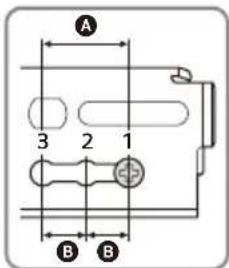
text_image
A 3 2 1 B Bnatural_image
Mechanical assembly diagram showing a tool interacting with a device housing (no text or symbols visible)text_image
Technical diagram showing mechanical assembly with labeled components and directional arrows indicating movement or forcenatural_image
Technical line drawing of a mechanical assembly with a screwdriver and housing (no text or symbols)text_image
-10° +10°text_image
1 2 3 G-A G-Bnatural_image
Mechanical assembly diagram showing a tool inserted into a housing with a screwdriver (no text or symbols)natural_image
Diagram showing a computer monitor connected to an internal device with a cable, no text or symbols presenttext_image
Technical diagram showing cable installation and assembly process with labeled components and directional arrownatural_image
Diagram of a computer interface showing an open monitor connected to a rectangular device with a cable inserted (no text or symbols present)text_image
Technical diagram showing mechanical assembly steps with numbered components and directional arrows indicating motionhttps://compliance.sony.eu
Hrvatski
Sony Corporation ovime izjavljuje da je ova oprema u skladu s Direktivom 2014/53/EU.
https://compliance.sony.eu
Česky
https://compliance.sony.eu
Dansk
https://compliance.sony.eu
Nederlands
https://compliance.sony.eu
English
Hereby, Sony Corporation declares that this equipment is in compliance with Directive 2014/53/EU.
The full text of the EU declaration of conformity is available at the following internet address:
https://compliance.sony.eu
Eesti keel
https://compliance.sony.eu
Suomi
https://compliance.sony.eu
Deutsch
https://compliance.sony.eu
Ελληνικά
https://compliance.sony.eu
Italiano
https://compliance.sony.eu
Latviešu
https://compliance.sony.eu
Lietuvių kalba
https://compliance.sony.eu
Norsk
Herved erklærer Sony Corporation at utstyrstypen er i samsvar med direktiv 2014/53/EU. EU-erklæring fulltekst finner du på Internett under: https://compliance.sony.eu
Polski
Register your product online now at: