PDUMH16HV - Power strip Tripp Lite - Free user manual and instructions
Find the device manual for free PDUMH16HV Tripp Lite in PDF.
User questions about PDUMH16HV Tripp Lite
0 question about this device. Answer the ones you know or ask your own.
Ask a new question about this device
Download the instructions for your Power strip in PDF format for free! Find your manual PDUMH16HV - Tripp Lite and take your electronic device back in hand. On this page are published all the documents necessary for the use of your device. PDUMH16HV by Tripp Lite.
USER MANUAL PDUMH16HV Tripp Lite
Important Safety Instructions 2
Installation 3
Features 5
Warranty & Product Registration 7
Espanol 8
Français 15
Pycckn 22
Deutsch 29
PROTECT YOUR INVESTMENT!
Register your product for quicker service and ultimate peace of mind.
You could also win an ISOBAR6ULTRA surge protector—a $100 value!

www.triplite.com/warranty
TRIPP·LITE

Manufacturing Excellence.
1111 W. 35th Street, Chicago, IL 60609 USA • www.triplite.com/support
Copyright © 2019 Tripp Lite. All rights reserved.
Important Safety Instructions
SAVE THESE INSTRUCTIONS
This manual contains instructions and warnings that should be followed during the installation, operation and storage of this product. Failure to heed these instructions may affect your warranty.

ImportantWarnings
- Operate the PDU at indoor temperatures between 32^ and 104^ (between 0^ and 40^ ) only.
- Provide adequate protection against excess currents, short circuits, and ground faults in accordance with local and national electrical code, such as NEC in the U.S.
- The mains socket that supplies the PDU should be near the PDU and easily accessible.
- The PDU provides convenient multiple outlets but it DOES NOT provide surge or line noise protection for connected equipment.
- The PDU is designed for indoor use only in a controlled environment away from excess moisture, temperature extremes, conductive contaminants, dust or direct sunlight.
- Do not connect the PDU to an ungrounded outlet or extension cords or adapters that eliminate the connection to ground.
- The power requirement for each piece of equipment connected to the PDU must not exceed the individual outlet's load rating.
- The total power requirement for equipment connected to the PDU must not exceed the maximum load rating for the PDU.
- Do not drill into or attempt to open any part of the PDU housing. There are no user-serviceable parts inside.
- Do not attempt to modify the PDU, including the input plugs and power cables.
- Do not attempt to use the PDU if any part of it becomes damaged.
- Do not attempt to mount the PDU to an insecure or unstable surface.
- Never attempt to install electrical equipment during a thunderstorm.
- Use of this equipment in life support applications where failure of this equipment can reasonably be expected to cause the failure of the life support equipment or to significantly affect its safety or effectiveness is not recommended. Do not use this equipment in the presence of a flammable anesthetic mixture with air, oxygen or nitrous oxide.
- The PDU must be installed by a qualified technician only.
- Install in accordance with local electrical codes. Be sure to use the proper over current protection for the installation, in accordance with the plug rating/equipment rating.
- The electrical sockets supplying power to the equipment shall be installed near the equipment and be easily accessible.
Installation
Note: Regardless of installation configuration, the user must determine the fitness of hardware and procedures before mounting. The PDU and included hardware are designed for common rack and rack enclosure types and may not be appropriate for all applications. Exact mounting configurations may vary.

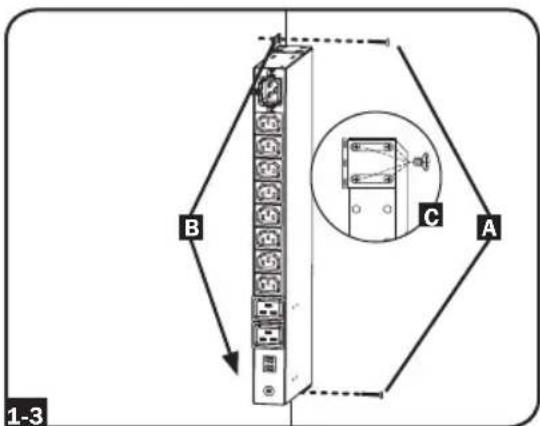
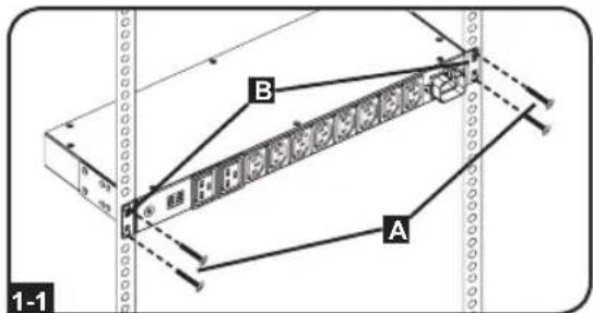
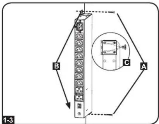
1U Rack Installation. Attach the PDU to the rack by inserting four user-supplied screws A through the PDU mounting brackets B and into the mounting holes of the rack rail as shown.

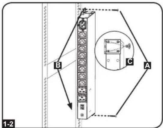
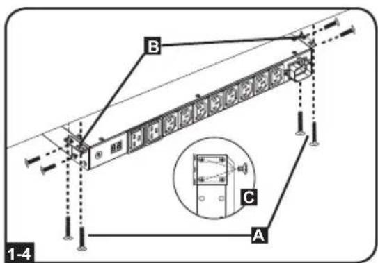
OU Rack Installation. Part 1: Remove the screws C attaching the mounting brackets to the PDU, change the orientation of the brackets as shown and reattach the brackets. Use only the screws supplied by the manufacturer or their exact equivalent (#6-32, 1/4" flat head). Part 2: Attach the PDU vertically by inserting two or more user-supplied screws A through the PDU mounting brackets B and into mounting points in the rack or rack enclosure.

Wall Installation. After repeating Part 1 above, attach the PDU to a stable mounting surface by inserting two or more user-supplied screws A through the PDU mounting brackets B and into secure mounting points on the mounting surface.

Under-Counter Installation. After repeating Part 1 above, attach the PDU to a stable mounting surface by inserting four user-supplied screws A through the PDU mounting brackets B and into secure mounting points on the mounting surface.


Installation
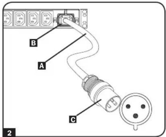
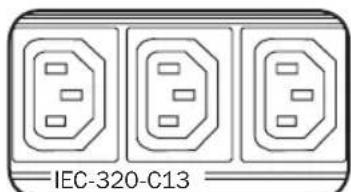
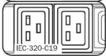
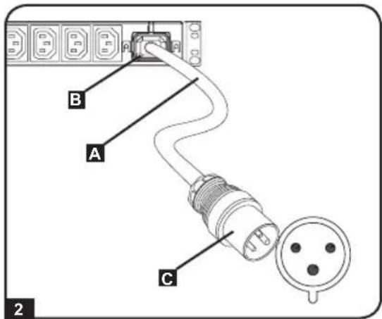
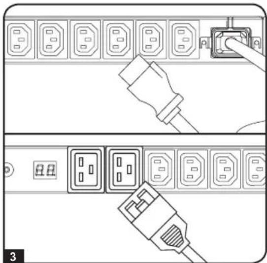
2 Input Power Cord Connection. Insert the IEC 320 C19 connector A of the input power cord into the IEC 320 C20 inlet B of the PDU. Connect the other end of the input power cord C to a compatible source of AC power. The PDU should be provided with over-current protection.
Note: The AC power source should not share a circuit with a heavy electrical load (such as an air conditioner or refrigerator).
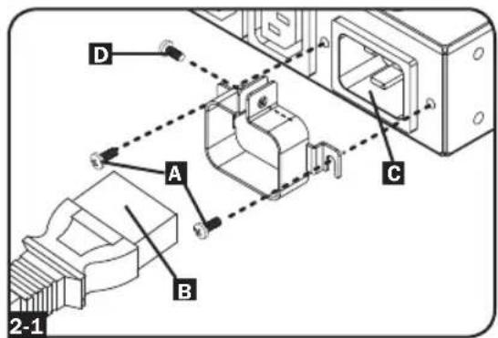
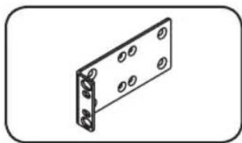
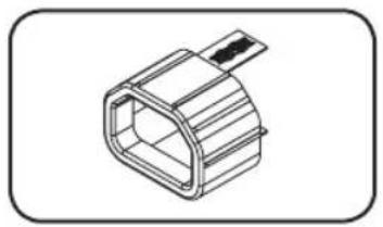
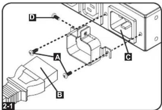
2-1 Input Cord Retention (Optional). Install the included bracket with the supplied #6-32 screws A then attach the included power cord to the PDU by inserting the IEC connector B of the power cord into the IEC power inlet C located near the end of the PDU. Use a supplied screw D to secure the power cord connection.
Note: As an alternative, a user-supplied power cord can be attached to the PDU by connecting it to the IEC inlet. Do not attempt to attach a user-supplied power cord unless it is certified to be compatible with the input power source that will be used by the PDU.
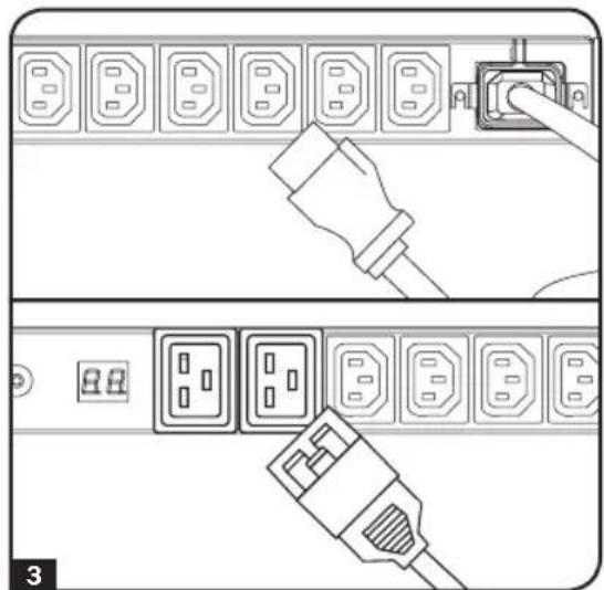
3 Attach equipment to the PDU. Do not exceed the load rating of the PDU. The total electrical current used by the PDU will be displayed on the digital meter in amperes.
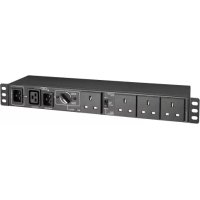
Features
Input Plug
Outlets: During normal operation, the outlets distribute AC power to connected equipment.
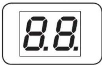
Ammeter: The total electrical current used by the PDU will be displayed on the digital meter in amperes.
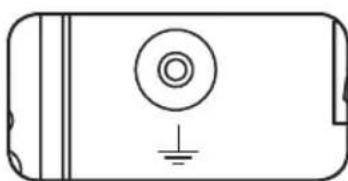
Grounding Lug: Use this screw to attach the connected equipment to ground.
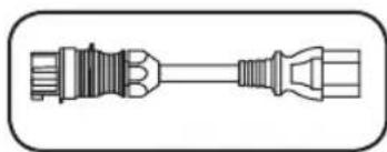
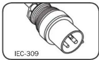
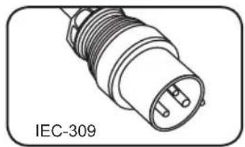
AC Input Power Cord: The included detachable cord has an IEC-320-C19 connector on one end that connects to the PDU inlet. The other end has an IEC-309 plug that connects to a compatible AC power source.
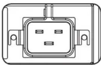
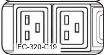
Power Inlet: The IEC-320-C20 power inlet connects to the included power cord or a compatible user-supplied power cord. The inlet includes a bracket to secure the cord connection.
Longer 1U Mounting Brackets: Use these brackets to mount the 1U PDU horizontally in a standard rack or rack enclosure. The mounting depth can be adjusted by attaching the brackets to different positions on the PDU.
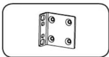
Shorter 0U Mounting Brackets: Use these brackets to mount the PDU in a 0U rack, wall or under-counter configuration for 1U PDU models.
Features
C14 Plug Sleeve (Optional): Use the included C14 plastic sleeves to secure plugs to receptacles. Attach the sleeve to the plug, making sure that the pull tabs remain outside the plug and that the fit is secure. To unplug equipment properly, use the pull tabs to remove the plug and sleeve from the receptacle.

C20 Plug Sleeve (Optional): Use the included C20 plastic sleeves to secure plugs to receptacles. Attach the sleeve to the plug, making sure that the pull tabs remain outside the plug and that the fit is secure. To unplug equipment properly, use the pull tabs to remove the plug and sleeve from the receptacle.
Warranty & Product Registration
2-YEAR LIMITED WARRANTY
Seller warrants this product, if used in accordance with all applicable instructions, to be free from original defects in material and workmanship for a period of 2 years from the date of initial purchase. If the product should prove defective in material or workmanship within that period, Seller will repair or replace the product, in its sole discretion. Service under this Warranty can only be obtained by your delivering or shipping the product (with all shipping or delivery charges prepaid) to: Tripp Lite, 1111 W. 35th Street, Chicago, IL 60609 USA. Seller will pay return shipping charges. Visit www.triplite.com/support before sending any equipment back for repair.
THIS WARRANTY DOES NOT APPLY TO NORMAL WEAR OR TO DAMAGE RESULTING FROM ACCIDENT, MISUSE, ABUSE OR NEGLECT. SELLER MAKES NO EXPRESS WARRANTY OTHER THAN THE WARRANTY EXPRESSLY SET FORTH HEREIN. EXCEPT TO THE EXTENT PROHIBITED BY APPLICABLE LAW, ALL IMPLIED WARRANTY, INCLUDING ALL WARRANTY OF MERCHANTABILITY OR FITNESS, ARE LIMITED IN DURATION TO THE WARRANTY PERIOD SET FORTH ABOVE; AND THIS WARRANTY EXPRESSLY EXCUSES ALL INCIDENTAL AND CONSEQUENTIAL DAMAGES. (Some states do not allow limitations on how long an implied warranty lasts, and some states do not allow the exclusion or limitation of incidental or consequential damages, so the above limitations or exclusions may not apply to you. This Warranty gives you specific legal rights, and you may have other rights which vary from jurisdiction to jurisdiction).
WARNING: The individual user should take care to determine prior to use whether this device is suitable, adequate or safe for the use intended. Since individual applications are subject to great variation, the manufacturer makes no representation or warranty as to the suitability or fitness of these devices for any specific application.
PRODUCT REGISTRATION
Visit www.triplite.com/warranty today to register your new Tripp Lite product. You'll be automatically entered into a drawing for a chance to win a FREE Tripp Lite product!*
- No purchase necessary. Void where prohibited. Some restrictions apply. See website for details.
Regulatory Compliance Identification Numbers
For the purpose of regulatory compliance certifications and identification, your Tripp Lite product has been assigned a unique series number. The series number can be found on the product nameplate label, along with all required approval markings and information. When requesting compliance information for this product, always refer to the series number. The series number should not be confused with the marking name or model number of the product.
WEEE Compliance Information for Tripp Lite Customers and Recyclers (European Union)

Under the Waste Electrical and Electronic Equipment (WEEE) Directive and implementing regulations, when customers buy new electrical and electronic equipment from Tripp Lite they are entitled to:
- Send old equipment for recycling on a one-for-one, like-for-like basis (this varies depending on the country)
- Send the new equipment back for recycling when this ultimately becomes waste
The policy of Tripp Lite is one of continuous improvement. Specifications are subject to change without notice.


Manufacturing Excellence.
1111 W. 35th Street, Chicago, IL 60609 USA • www.triplite.com/support
1111 W. 35th Street, Chicago, IL 60609 USA • www.triplite.com/support
1111 W. 35th Street, Chicago, IL 60609 USA • www.triplite.com/support
1111 W. 35th Street, Chicago, IL 60609 USA • www.triplite.com/support
1111 W. 35th Street, Chicago, IL 60609 USA • www.triplite.com/support
PykoBoDCTBO NOJIb3OBaTeIa
CtoeHbI PDU c
n3MepnteJIeM
Modélb: PDUMH16HV
(CepinHbI Homep: AG-00D9)
Baxhble yka3aHnno no texHnke 23
6e3onachoctn
YcTaHOBka 24
Bo3MOxHocTh 26
TapaHTnHbIe 6o3aTeIbCTBa 28
English 1
Espanol 8
Français 15
Deutsch 29
EAC


1111 W. 35th Street, Chicago, IL 60609 USA • www.triplite.com/support
OxpaHaeTcA ABTopcknM npaBOM © 2019 Tripp Lite. NepeneuAtka 3anpeuaeTcA.
Baxkhble yka3aHnno texHnke 6e30nacHoCTn
COXPAHNTE HACTOUIYKA3AHNIA
B hactoem pykooboctbe codepkaTcya3aHnN npedynpejxden, KOtOpbIe Heo6xOdmo c6bnOdaTb B npocece yctahOBKn, 3Kcnnyatauunn XpaHeHHaDaHHoro n3deHn. HrhopnpobAHne 3THX yka3aHn N npedynpejxden MoKet npNBecTN K notepe rapaHTm Ha n3deHnE.

Baxhble npedynpekdeHn
- 3KcnJyatnpyTe PDU toIbko npn KOMHaTHbIX Tempepatpax (B dnaanaOHe ot 0 do 40^)
- ObecnebyTe DoCTaTOUHO HaedKHyIO 3auNTy OT n36bIToOHbIX TOKOB, KopoTKnX 3aMbIKH N 3aMbIKHn Ha 3eMJIIO B COOTBeTcTBn C MeCTHBIMN O6ueHaCIOHApHBIMN 3JeKTpoTeHXHueCKHMn HopMaMn n npabunamn (Hanp., NEC B CLUA)
Cetebarpo3eKa,HTaHuaPDU,doJxHaHXoDttbCBAHn3HrOINB CBO60HOM DoCTyne. - 5nok pacnpedeHn nTahn (PDU) ochaen HeckoIbKIMu yO6hBMn po3eTKamn, Ho HE obecneuBaET 3aunTy NOkHoueHHoro O6OpyDobAHnO T Bb6pocOB HnprJxEHn U WymOB B IHHm.
- PDU npedha3aeh TOIbKO IINr IcNOJIb3OBAHnB 3aKpbIbIX NOMeueHnX C peryNpyEmbIM MKNpOKJIMMATOM BdAnOT NCTOCHNKOB NOBIIeHHHO BnAaXHOCTN, EKTpeMaJIbHbIX TEMNEpaTyp, 3NeKTponpoBDhIX 3arP3HNTeJe, nbIn IN pRMOr COJIHeHOro CBeta.
He noKnIouaHTe PDU K He3a3emHHoH po3eTke, a TaKKe K yDInHITeJIaM IIN nepexoHNkAM, He MeIOUIM 3a3eMJIeHn.
Mouhoctb, nontpe6nemar kaoJdoeHNHcE OOBpyoBaHnna, noKnHoueHOrO K PDU, He doxkna npBbIaTb MaKcImaJIbHO dOnyCTmMyHO Harpy3ky Ha OTdeJIbHyIO p03eKy.
CymmaHnMoUHocb,Notpe6IeMaHOBAHm,NOKIOueHHbIM K 6IOky paCnpedeHn HNTAHN (PDU), He DonxHa npeBbIaTb erO MaKcImaNbHO DOnyCTMHyHO Harpy3Ky.
He BbICBepnBaIte OTBepCTn B KOpnyce PDU n He nbTaIaTecb BCKpbITb KaKyIO-JN6o erO yactb. BHyTPH HrO HET DeTaJe, O6CNYKBAeMbIX NOnb3OBaTeJEM.
He BVOCHTe 3MeHEn B KOHCTpyKcIPO PDU, BKJIIOyAe BXoDHbpe pa3BeMbI Na6eJIIN TnTaHn.
He nCnoB3vIe PDU B cIyue noBpeXeHnJIb6oN I3 erO yacte.
He yctaHaBnBaIe PDU Ha He3aKpeJIeHHoN mI HyeCTOnuHBOI NOBepxHOCTN. - Hn B Koem clyuae He npou3B0DInTe MOHTax 3neKtpoo6OpydoBaHn BO BpeM rpo3bl.
He pekomehnyetcncnolb30BaHne daHHoro 6obpyoOBaHnB CnCTeMax Xn3HeoBeCneHnra, rpe erO BbIXoN 3CTPOIpeINIOJNOKHTeJIbHO MOKeT PnIBeCTN K nepe6oM B pa6ote 6obpyoOBaHn Jn3HeoBeCneHnna INN B 3HaHTeJIbHO Mepe CHn3NTb Ero 6e3ONaCHOCt b INN eΦΦeKTHBHOCTb. He nCNoJIb3yTe DaHHoe 6obpyoOBaHnE B npNCyTCTBmN BocIIaMeHryUeNcAheCTeTNUeCKOcmecn c BO3DyXOM, KNCLOPODOM INN 3aKNCbIO a3Ota. - YctaHObKa PDU DOnXHa npOn3BODInTbcS TOnbKO KBaIINΦuNpOBoAHbIM TexHmecKm CneLNaHnCTOM.
- YctaHOBky CJIeDyET IPOUN3BOINb B COOTBECTBm C MecTHbIMN 3JIeKTPoTeHXHueCKMn HOpMaMn INpabINAMn. O6ra3aTeNbHO NcNOJb3yIte NOxOJaune dIpy YcTaHaBInBaEMOn CnCTEmbl 3aUHTbIeYCTPOECTBA B COOTBECTBm C HOMHNAMn, Yka3aHHbIMN Ha pa3bEmax/ObOpyOBAHmN.
3NeKtpnueckne po3ETKn, Hepe3 KOtOpBle OcyuIeCTBJIeTcra 3JeKtpoNTaHHe o6OpydoBaHna, DOnJXbI 6bITb yCTaHOBHeB b JERKOIOCTYINHom MecTe B6NJ3N Hero.
yctaHOBka
Ipumeyaue. He3aeucuMo om KOHphiaypaauu ycmaHOeKo nolb3oeamelb doJxhen ycmaHOobmb npuzodnoctb ochmku u npednonaaembix npouedeyp do hauana mohmaxa. Bnok paCnpedeHnur numahura (PDU) u 6xo7aag e e0 kOMIIeKm ochmka npedHa3naHbI dny oBlybIX munoe ukafoe u moaym He noxdoxumb dny ecex ueleu npumeHenru. YcmaHOooHbIe KOHphiaypaauu Moaym pa3nuambc8 deomanx.
1-1 YcTaHOBka B WkaΦ BbICOTOn 1U.3aKpeNITe PDU B WkaΦy NytEm BBepTbIBaHnY YeTbIpex BnHTOB A (He BXOJaUxN B KOMJIeKT NocTaBKn) UpeE3 MOHTaXHbIe KPOHSTeHbI PDU B MoHTaXHbIe OTBepCTnHaNPabJIIOSei WkaΦa, KaK NOKa3aHo Ha pncyHke.
1-2BepTKaJIbHa yCTaHOBa B uKaΦ (OU). 1: BBiBepHInTe BNHTbI G, oBeCneuBAHOUe KpeJIeHne MOHTaXHbIX KPOHtEINOB K PDU, N3MeHnTE NOLOXeHne KPOHtEINOB, KaK NOKa3aHO Ha pUCyHKe, IN npIKpeNTe KPOHtEINbI Ha IpexKHee MeCTO. IcNoJIb3yIte TOnbKO BnHTbl, NoCTaBnReMbIe npON3BOJNTeJIeM, INN INx ONHbI aHaIor (#6- 32, 1/4" c NotaHOBKn). AcTb 2: PpIKpeNTe PDU BepTKaJIbHO NyTEM BBePTbIBAHnI DByX INN BoJee BnHTOB A (He BXoJauNX B KOMJIeKT NocTaBKn)Yepe3 MOHTaXHbIe KPOHtEINbI PDU B MoHTaXHbIe OTBepCTNa CToKN INN uKaFa.
1-3 HacteHHbIM MOHTaK. NocIe NOBTOpeHnA DeiCTBn, OINcaHHbIX BblIe B YAcTn 1, npKpENITe PDU K yctOuHBOM MOHTxHOI NOBepXHOCTN NyTeM BBepTbHAHNy DByx INI60JIe BnHTOB A (He BXoJUnx B KOMIIKeT nOcTaBKn) Upe3 MoHTaxHbIe KPOHtEHHbI PDU B MONTaXHbIE OTBepCTnHa MOHTaXHOI NOBepXHOCTN.
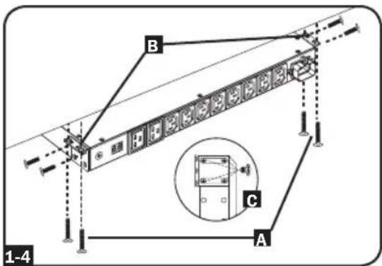
1-4 MoNTaX NOI npINaBkOM. Nocne NOBTopeHn
DeiCTBn, ONICAHbIX BblSe B YactN 1,
PnIKpeNITe PDU K yctOuHBO MONTaXHO
NOBepxHOCTN IyTEM BBePTbIBaHn YcTbIPex
BHTOB A (He BXoJAAUX B KOMNJIeKT NOCTaBKU)
Yepe3 MOHTaXHbIe KPOHSTeHbI PDU B
MOHTaXHbIe OTBepCTNHa MOHTaXHO
NOBepxHOCTN.
yctaHObka
2ПОДКИОЧЕНБXODHOROshypaNTAHNBACTaBte pa3bEM Tnna IEC 320 C19ABXODHORO shHpya NTAHNBO BXODHOpa3bEMTnnaIEC320C206Joka pacnpedeHINNA(PDU).POnKIOUHTeDpyrO KOHeuBXODHOro shHpya NTAHNARKCOBMECTMOMUYNCTOHNKY NtAHNNEpeMeHHoroToKa.PDUdoJxhen6bTB OCHauIeH3aunTOIOTnepeRpy3OKno TOky.
Ipumeyaue. HcmoHuk numaHua nepemehno2o moka He doJKeH haxodumbc8 06uem KOhype c 6oIbwo 3neKmpueeckou Haepy3kO (makou kAK KOduuohep unx XOnodunbHuK).
2-1ФИKcaunBxOJHOro shHpya (OnuHOHaJIbHO). YcTaHOBInTe KPOHHTeIN3 KOMnIeKTA C NOMOUBHXOJrAUXCR B TOM JKe KOMnIeKTE BnHTOB #6-32 A,3aTeM NOIDCOEINHITe UHyp NITAHNlN3 KOMnIeKTA K PDU, BCTaBNB pa3bem Tnna IEC B shHpya NITAHNBA BxOJHOH pa3bem NITAHN4 Tnna IEC C, pAcNOJIOKeHHbIy KpAra PDU. Ppi NOMOUI BNHTA, BXOJaERo B KOMnIeKT D, 3aΦNKcpyInTe BXOHDH HHP B NODKJIIOHeHHOM COCTOHHN.
PpumeyaHue. KaK eapuaHm, noJIb3OBeamJIb moXem noDKIIOUcMb PDU npu nOMoU cEOe20 co6cmEHHOe 0Hypa numAHur, ecmaBnEMOzo 0e 8xodHO pa3bEM muna IEC. He cIeDyem npou3eOdumb noKDIOUeHue c nomoubIO npuOsbemaMOzo omdenbHO uHpya numAHur, He cepmuDuuupoeaHHOz Ho coBMeCmUMOCMb UcMoUHukOM numAHur, uCNoJb3yEmbIM Ha 6xoDE PDU.
3 PoiKIOHnTe OobpyOBoAHne K PDU. He npEbIaIe HOMHaIbHyIO HaPuy3ky PDU. CymMapHbI 3JIeKTPuYeCKNI TOK, nTpe6IaEMbI PDU, BbICBeuBaETcRa HnHdNkatope UΦpOBOrO N3MepNTeB aMnepax.
Bo3MOXHOCTHN
BxoHno pa3bem
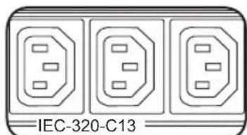
Po3eKn: B WItaTHOM pexnme pa6oTbI po3eTKn pacnPepenHOT MOUHOCTb IepemEHoro TOKa MExdy NODKNIOeHHbIMN K HIM 3JIeMeHTAMn O6OpyOBOHn.
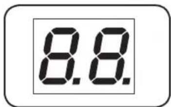
AmnepeTp: CymMaphbl 3nEeKtpueeCKn TOK, nOte6nembl PDU, BbICBeuBaETcHa HnDnKaTope uNΦpOBOrO n3MepntJIa B ampepa.
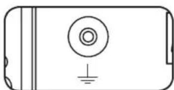
KneMma 3a3emnHn: nIa 3a3emnHn NOkNIOeHHORO 60OpydoBaHn IcNoJIb3yIte 3TOT BNHT.
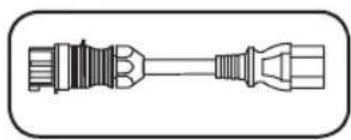
Bxodnoh shyp nHTAHnna nepemehHoro TOka: Coepkaunnc B KOMPJIeKTe NOCTaBKn OTcoEINHReMbI shHyp OCHaUeH C OJHO KOHca pa3bEmom TnPa IEC-320-C19, BKJIIOuHaEmbIM BO BXoHNO pa3bEm PDU. Ha dpyrom KOHcne NMeETcra pa3bEm TnPa IEC-309, NOdKNIOUaEMbl K COBMECTUMOMy IVCTOUYHKy NITAHnna nepemehHoro TOka.
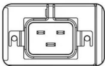
Bxodno pa3bem nHTAHN: BXoHO pa3bem nHTAHn Tnna IEC- 320-C20 noKNIouaETc K noCTabIeMOMy B KOMPNeKeTse Hhypuy nHTAHN INI K npNo6peTaEMOMy OTJeNbHO shHpy nHTAHN, COBmecTUMOMy C HIM. JINI qKcaUN NODCOEINHeHHORO shHypa nHTAHN BXoHO pa3bem OChaueh CneuaJIbHbIM KPOHTeHOM.
YdHHeHHbIe MoHTaXHbIe KPOHTeHbI pa3Mepom 1U: NcNoB3yIte 3TN KPOHTeHbI dIra TOpN3OHTaNbHO MOHTaJa PDU pa3Mepom 1U B cTaHapTHyIO CTOnKy IIN UkaΦ. MoHTaXHa rLy6Ha MoKeT peYnIpOBaTbcra NyTeM KpeNJIeHnRA KPOHtEiHOB K dpYmM ToKam PDU.
YKOPOeHHbIe MOHTaXHbIe KPOHwTeHbI DnB BepTKaJIbHO MOHTaxa: NcONJb3yIne 3Tn KPOHwTeHbI DnB BepTKaJIbHO MOHTaxa PDU B cToKy (0U), a TAKKe Ha cTeHy nIN NOd pPnIabOK (dN MaDene PDU BBICOTOn 1U).
Bo3MOXHOCTN
Myfpa pa3bema C14 (onu): 3aФнкуte pa3bembl B pO3eTKax npn NOMOUI BXODIUX B KOMIIeKTI NlactMaCCOBbIX MyfT noD pa3bembl C14. PnIKpeNITe MyfTy K pa3bemy, y6eINBUnCb B Tom, YTO ee r3bUKN OctaOTcra 3a npeJeAMn pa3bema I NIOTHO pInneraOT K Hemy. IINr npABINbHoro OTcoeINHeHn OBOpYDoBaHn CNeyET BbIHmAtb pa3bEm C MyfToI INo3 po3eKn, DePkAc b 3a Ra3bUKN.
Myfpa pa3bema C20 (onu): 3aФнсуte pa3bembl B pO3eTKax npn NOMOUI BXODIUX B KOMIIeK TIIaCTMaCCOBbIX MyfT noD pa3bembl C20. PnKpEnTe MyfTy K pa3bemy, y6eINBUNCB B TOM, YTO ee I3bUKN OCTaOTcR 3a IpeIeIamn pa3bema n NIOTHO pNIneraIoT K Hemy. IJr npabInbHoro OTcoeINHeHn O6OpyIDOBAHn CNeIyET BbIHmAtb pa3bEm C MyfToI n3 po3eKn, DEpkacb 3a Ra3bIKn.
ГараHTиHьIe 6ЯЗaTeЛbCTBa
YcnoBna 2-JeTHei orpaHueHHo rapaHTn
IpoaBeu rapaHTnpyET OTCyTCTBne 3HaayabHbIx DepeKTOB MaTePnAna nn H3ROTOBJIeHn B TeueHne 2
JeT C MOMENTA nepBOI NOKyKN DaHHORO IN3DeNRA PnU yCNOBn ERO nCNOJb3OBAHn B COOTBeTCTBn CO
BCEMn PnIMeHMbIMn K HeMy yKa3aHnMa. B cnuyae npoRbHeHn KaNX-Jn60 DepeKToB MaTePnAna nn
IN3ROTOBNEHn B TeueHne yKa3aHHoro nepNoa IpoaBeu ocUcEcbIeR peMOHT nn 3aMeHy daHHORO
IN3DeNna NCKIOHTeNbHO NO CBOEmy ycMOTpeHnIO.
ENCTBNE HACTOJI E I RAPAHNTI HE PACNPOCTPAHRETCA HA CJIYAH ECTECTBEHHORIO3HOCA II NIOBPEKJDEHNA B PE3yIbTATE ABAPIN, HEHAJIEXKAUETO NCIOJIb3OBAHNA, HAPUJEHNA I PABIN 3KCIYATAUIN INI XANATHOCTN. IPODABELI HE I PEOIOCTABJARENHKAKNX BIBPAXEHHbIX TAPAHNTI 3A NCKLIQUEHHEM IPRMO I3IOXJEHNOB HACTOJIEM DOKUMHETE. 3A NCKLIQUEHME CJIYAAEB, 3APLESEHHbIX DEIECTBYIOUIM 3AKOHODATEJBCTBOM, BCE IOPDA3YMBAEMbIE TAPAHNTI, BKIOUAY BCE TAPAHNTI IPINOIOHOCTN IJI NIOJONJIb3OBAHNA IIO HA3HAUEHNIO, OPAHUNeBI NO IPOJOJXITIELBOHCTNI DEIECTBNA BIIWEYKA3AHHBIM TAPAHNTINHBIM CPOKOM; KPOME TOTO, IN3 HACTOJI E I RAPAHNTI YBHbIM OBPA3OM NCKLIQUAHOTC BCE IOBOUHbIE, CJIYAHNBIE IN KOCBEHNBLE YbItKN. (B HeKOTOpbIX Wtatax He Donyckaetc BBeDeHne orpaHNeHn Ha IPOJOJXITIELBOHCTB DeIECTBNA Tex INI INhIX NIOpa3YMBAEMbIX rapaHTN, A B HeKOTOpBX - NCKLIQUEHNE INI ORpAHueHHe pa3mepa No6oHybIX INI KOCBeHNbIX y6bIKOB. B 3tIX CNyauX BIIeHNIOXeHHbIE OPAHUNeHNA INI NCKLIQUEHNA MOrT Ha Bac He pacnpocpaHrTbcra. HactOuaa rapaHTN npeIOCTabJIeR Bam KOHNPeTHbIe IopNiueckne npaba, a Habop dpynx BaWix npab MoKET 6bITb pa3NIuHbIM B 3aBNCIMOCTI OT UOpncndkun).
BHIMAHHE! Do hauana nCnoJb3ObaHn daHHoro yCTpoIcTba noIb3oBaTeJI doJXKeH y6eINTbcB TOM, qTO OHO YBnEeTcR npiroDnHbIM, COOTBeTCTByIOuIM IIN 6e3OnacHbIM dIg PpeINoIraemOrO npimeHeHn. B CBaN C 60nbMpa3Hoo6pa3nEM KOHKPeTHbIX npimeHeHn pOn3BOdnteJI He daET KaNX-JI60 3aBepeHn INI rapaHTn OTHocNTeJIbHO npiroDHOCTn daHHbx IN3DeJI NJa KAKOrO-JI60 KOHKpETHORO npimeHeHn INI INx COOTBeTCTBIA KAKIM-JI60 KOHKpeTHbIM Tpe6OBaHnM.
IeHTnФkaUHbIe HOMepa,CBnTeJIbCTByIOUneO COOTBETCTBIM HOpMaTHBbIM Tpe6oBaHnA
C cIbIO nIeHTnHcKaun, a TaKoe cepTnHcKaun COOTBeCTBn HOpMaTnBHBIM Tpe6oBaHnM, npio6peTeHHOM BAmn I3dennIO KOMNaHm Tripp Lite npncBoEH yHnKaIbHbI cepHbI Homep. CepHbI Homep, BmecTe co BCEHne Heo6xOaIMOn INHΦopMaun E MapKnPOBkAMn 06 Odo6peHN, yKa3AH Ha JApJIke n3rTOBtEnI, npNKpePHeHOM K I3dennIO. Ppi 3anpoce HΦopMaun O COOTBeTCTBn HOpMaTnBHbIM Tpe6oBaHnM Bcerda Coo6uaaTe cepNbHb Homep n3dennIA. He cNe dyET nyTaTB cepNbHb Homep C MapKo nn Homepom MoDeEN n3dennIA.
HfopmaunIg KnnehtOB KOMnaHH Tripp Lite o co6nIOeHN Tpe6oBaHH dIpeKTHBb EC 06 OTxOax 3JeKtpnueckoro n 3JeKtpoHHoro 6OpydoBaHH (WEEE)

Corlaacno dnpkeTnBE EC o6 oTxdoax 3neKtpueckoro n 3neKtpoHHOrO 0bOpdyOBaHn (WEEE) npimEmHMbIM HOpMaM B ClyaX, KOrJa nokyNaTeJN npNo6peTaOT HOBoe 3neKtpueckoe n 3neKtpoHHoe 06opdyOBaHn KomnaHn Tripp Lite, OHn NMeOt npaBO Ha cnedyUoee:
- Otnpabky cTaporo o6bopyoBaHn, KOtOpoe rBnEeTc3KBNBaJIeHTbIM NO KOnIYeCTBy INDeHTNHybIM NOnyHeHHOMy HOBOMy o6bopyoBaHnIO, Ha yTnIn3aUIO (3TO yCIOBne MOKeT OTnNuYbSc B 3aBNCIMOCTn OT CtpaHbl)
- OTnpaBky HOBOrO o6OpyDoBaHnI O6paTHo Ha yTunN3aCnIO, KOrDa OHO B KOHeuHOM ITORE CTAHOBITcN3HOWeHHbIM
KomnaHn Tripp Lite nocToHHo coBepueHCTByET CBOIO npOdyKUHO. B CB3N C 3TNM BO3MOXHO N3MeHeHnTExHuecknx xapaKTepeuCTNK 6e3 ppeBapntelbHoro yBeDOMneHn.


1111 W. 35th Street, Chicago, IL 60609 USA • www.triplite.com/support
Benutzerhandbuch
1111 W. 35th Street, Chicago, IL 60609 USA • www.triplite.com/support
1111 W. 35th Street, Chicago, IL 60609 USA • www.triplite.com/support