
WorkWise WWSS1327RWTC - Wall mount for computer monitor Tripp Lite - Free user manual and instructions
Find the device manual for free WorkWise WWSS1327RWTC Tripp Lite in PDF.
| Product Type | Wall-mounted sit-stand monitor arm |
| Brand | Tripp Lite |
| Model | WorkWise WWSS1327RWTC |
| Maximum Load Capacity | 6 kg (13.2 lb) |
| VESA Compatibility | 75 x 75 mm and 100 x 100 mm |
| Main Material | Steel |
| Color | Black |
| Number of Arms | 2 (monitor arm + keyboard arm) |
| Height Adjustment | Yes, gas spring |
| Tilt | Yes, adjustable |
| Swivel | Yes, adjustable |
| Pivot | Yes |
| Keyboard Tray Included | Yes |
| Installation Type | On wood stud or concrete wall (anchors provided) |
| Intended Use | Indoor only |
| Warranty | 5-year limited |
| Recommended Maintenance | Check safety every 3 months |
| Cleaning | Soft dry cloth |
| Box Contents | Wall rail, monitor arm, keyboard arm, keyboard tray, hardware, hex keys |
Frequently Asked Questions - WorkWise WWSS1327RWTC Tripp Lite
User questions about WorkWise WWSS1327RWTC Tripp Lite
0 question about this device. Answer the ones you know or ask your own.
Ask a new question about this device
Download the instructions for your Wall mount for computer monitor in PDF format for free! Find your manual WorkWise WWSS1327RWTC - Tripp Lite and take your electronic device back in hand. On this page are published all the documents necessary for the use of your device. WorkWise WWSS1327RWTC by Tripp Lite.
USER MANUAL WorkWise WWSS1327RWTC Tripp Lite
Register your product for quicker service and ultimate peace of mind.
You could also win an ISOBAR6ULTRA surge protector—a \$100 value!
www.tripplite.com/warranty


text_image
TRIPP·LITE
1111 W. 35th Street, Chicago, IL 60609 USA • www.tripplite.com/support
Copyright © 2018 Tripp Lite. All rights reserved.
Important Safety Instructions
NOTE: Read the entire instruction manual before you start installation and assembly.

WARNING
- Please read the entire instruction manual before you start installation and assembly. If you have questions about any of the instructions or warnings, please contact Tripp Lite.
- This desk stand is designed to be installed and used only as specified in this manual. Improper installation of this product may cause damage or serious injury.
- Be sure the supporting surface will safely support the combined weight of the equipment and all attached hardware and components.
• Always use an assistant or mechanical lifting equipment to safely lift and position the equipment. - Tighten screws firmly, but do not over-tighten. Over-tightening can cause damage to the items and reduce their holding power.
- This product is intended for indoor use only. Using this product outdoors could lead to product failure and personal injury.
Warranty & Product Registration
5-Year Limited Warranty
Seller warrants this product, if used in accordance with all applicable instructions, to be free from original defects in material and workmanship for a period of 5 years from the date of initial purchase. If the product should prove defective in material or workmanship within that period, Seller will repair or replace the product, in its sole discretion.
THIS WARRANTY DOES NOT APPLY TO NORMAL WEAR OR TO DAMAGE RESULTING FROM ACCIDENT, MISUSE, ABUSE OR NEGLECT. SELLER MAKES NO EXPRESS WARRANTIES OTHER THAN THE WARRANTY EXPRESSLY SET FORTH HEREIN. EXCEPT TO THE EXTENT PROHIBITED BY APPLICABLE LAW, ALL IMPLIED WARRANTIES, INCLUDING ALL WARRANTIES OF MERCHANTABILITY OR FITNESS, ARE LIMITED IN DURATION TO THE WARRANTY PERIOD SET FORTH ABOVE; AND THIS WARRANTY EXPRESSLY EXCLUDES ALL INCIDENTAL AND CONSEQUENTIAL DAMAGES. (Some states do not allow limitations on how long an implied warranty lasts, and some states do not allow the exclusion or limitation of incidental or consequential damages, so the above limitations or exclusions may not apply to you. This warranty gives you specific legal rights, and you may have other rights which vary from jurisdiction to jurisdiction).
WARNING: The individual user should take care to determine prior to use whether this device is suitable, adequate or safe for the use intended. Since individual applications are subject to great variation, the manufacturer makes no representation or warranty as to the suitability or fitness of these devices for any specific application.
PRODUCT REGISTRATION
Visit www.triplite.com/warranty today to register your new Tripp Lite product. You'll be automatically entered into a drawing for a chance to win a FREE Tripp Lite product!*
* No purchase necessary. Void where prohibited. Some restrictions apply. See website for details.
Tripp Lite has a policy of continuous improvement. Specifications are subject to change without notice.
Component Checklist
IMPORTANT: Ensure all parts according to the component checklist have been received prior to installation. If any parts are missing or faulty, visit www.triplite.com/support for service.
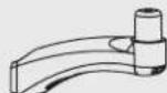
A
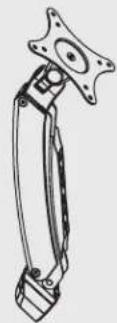
Display Arm
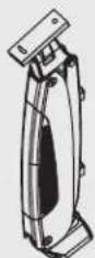
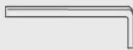
Keyboard Arm (B) Thin Client Keyboard Tray Wall Rail
Keyboard Tray
Holder
Keyboard Arm (A)

Keyboard Arm Attachment
B

M4 × 12 (x4)
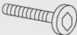
M6 x 15 (x2)
C
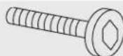
M5 x 18 (x1)
M5 x 10 (x4)

M5 (x4)

14×6.5×1(x1)
D
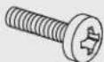
M6 × 25 (x3)
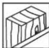
(x3)
E

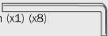
3 mm (x1)
4 mm (x1) 5 mm (x1) (x8)


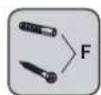
F
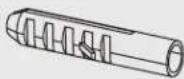
Φ8×40(x3)
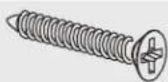
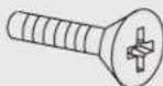
M6 x 50 (x3)
G
M5 x 12 (x4)

M5 (x4)
H

M6 (x2) (x1)

Assembly
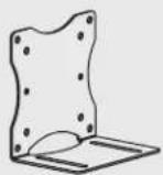
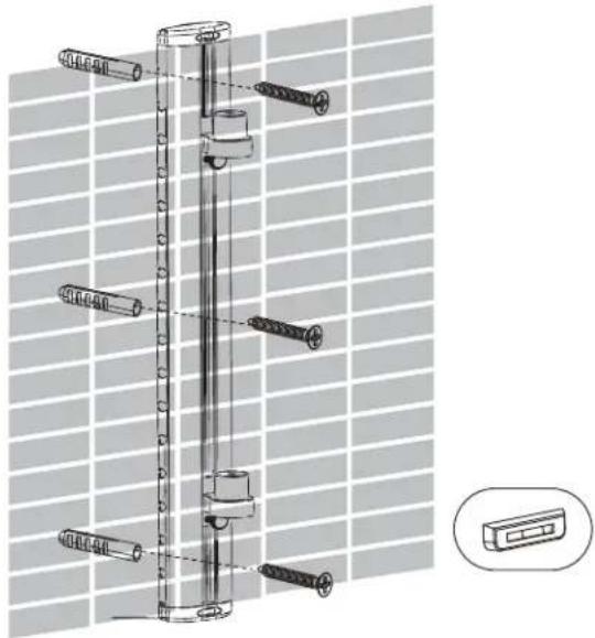
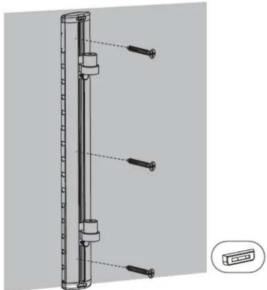
① Attach wall rail to wall.
For wood stud wall installation.

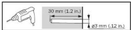
text_image
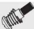
30 mm (1.2 in.) Ø3 mm (.12 in.)

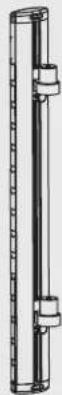
natural_image
Technical line drawing of a vertical cylindrical device with four inserted pins, shown with a close-up inset of the component (no text or symbols present)Or For concrete wall installation.


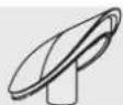
natural_image
Technical line drawing of a mechanical assembly with multiple bolts and a component, shown against a grid background (no text or symbols)WARNING
- When mounting on a wood stud wall, make sure mounting screws are anchored into the center of the studs. Use of a stud finder is highly recommended.
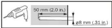
- When installing wall mounts onto a concrete masonry unit (also known as a CMU or "cinder block"), verify that the actual concrete thickness is at least 35 mm (1-3/8") in order to hold the concrete anchors. DO NOT DRILL INTO MORTAR JOINTS! Be sure to mount the wall mount with the included concrete anchors and anchor bolts onto solid sections of the blocks. The solid sections can generally be found 25 mm (1") toward the middle of the block from either end. An electric drill on a slow setting is suggested to drill the hole rather than a hammer drill so as to avoid breaking out the back of the hole when entering a hollow section.
• Installers are responsible to provide hardware for other types of mounting situations.
• Installers must verify that the supporting surface will safely support the combined load of the equipment and all attached hardware and components.
Assembly
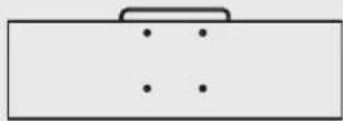
② Assemble keyboard tray.
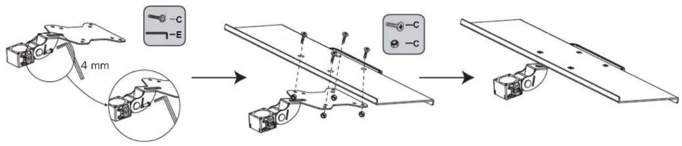
text_image
4 mm -C -E3 Attach keyboard tray to keyboard arm.
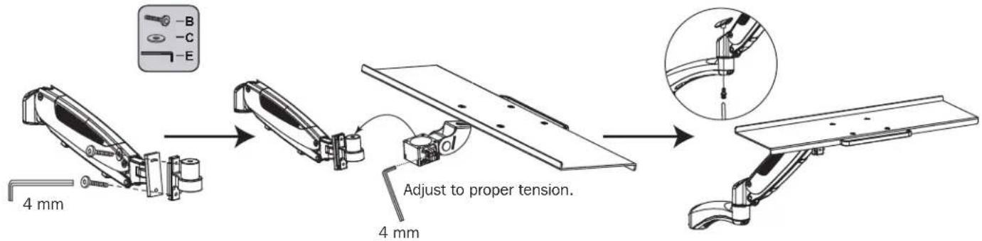
text_image
4 mm B C E Adjust to proper tension. 4 mm④ Attach keyboard tray and monitor arm to wall rail.
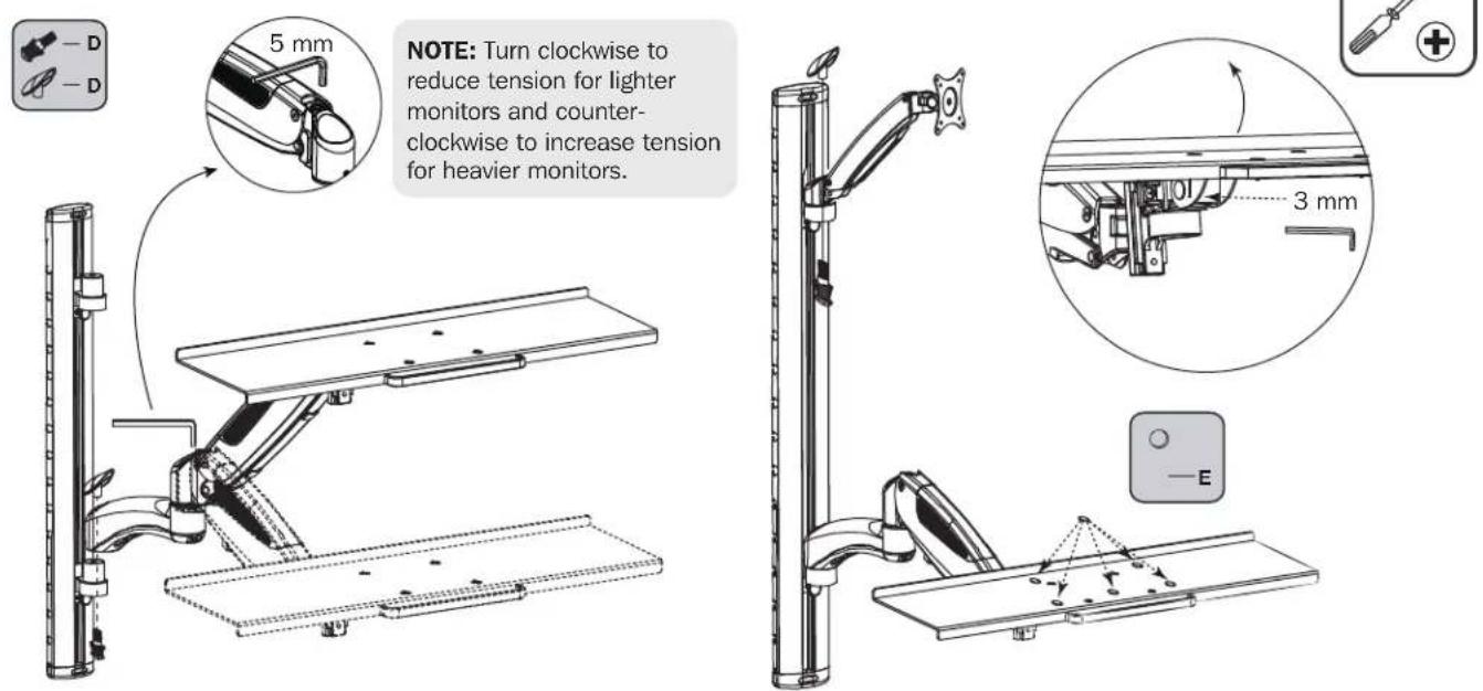
text_image
5 mm NOTE: Turn clockwise to reduce tension for lighter monitors and counterclockwise to increase tension for heavier monitors. 3 mm — EAssembly
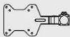
⑤ (Optional) Attach thin client to VESA plate.
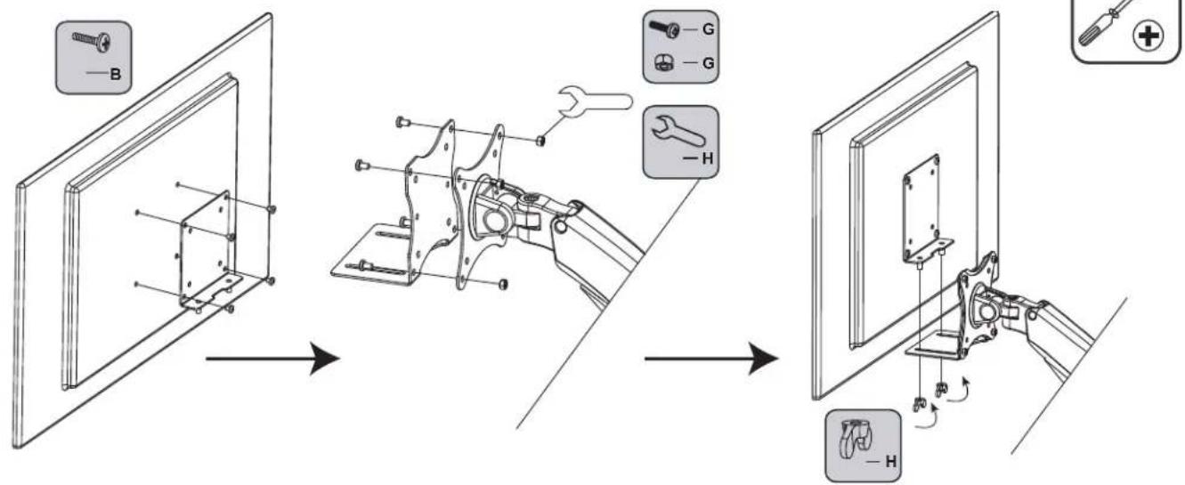
text_image
Technical diagram illustrating the assembly of a mechanical component with labeled parts and directional arrows indicating steps.6 Adjust tension of keyboard arm and monitor arm.

text_image
Adjust to proper tension. 3 mm Turn the knobs to horizontally adjust the thin client. Use the included a hex keys to adjust the height tension of the mechanical spring arm, to keep different weight of monitors still at any position. NOTE: Turn counter-clockwise to reduce tension for lighter monitors and clockwise to increase tension for heavier monitors. 5 mm
CAUTION: DO NOT EXCEED MAXIMUM LISTED WEIGHT CAPACITY (13.2 lb. / 6 kg). SERIOUS INJURY OR PROPERTY DAMAGE MAY OCCUR!
Maintenance
- Check that the bracket is secure and safe to use at regular intervals (at least every three months).
- Please visit www.tripplite.com/support if you have any questions.
text_image
30 mm [1.2"] Ø 3 mm [0.12"]
natural_image
Technical line drawing of a vertical cylindrical device with four inserted pins, shown with a close-up inset of the component (no text or symbols present)natural_image
Technical line drawing of a mechanical assembly with multiple bolts and a component, shown against a grid background (no text or symbols)ADVERTENCIA
text_image
Technical diagram illustrating the assembly of a mechanical component with labeled parts and directional arrows indicating steps.1111 W. 35th Street, Chicago, IL 60609 USA • www.tripplite.com/support
natural_image
Technical line drawing of a vertical cylindrical device with four inserted pins, shown with a close-up inset of the component (no text or symbols present)natural_image
Technical line drawing of a mechanical assembly with multiple bolts and a component, shown against a grid background (no text or symbols)AVERTISSEMENT
text_image
Technical diagram illustrating the assembly of a mechanical component with labeled parts and directional arrows indicating assembly steps.1111 W. 35th Street, Chicago, IL 60609 USA • www.tripplite.com/support
natural_image
Technical line drawing of a vertical cylindrical device with four inserted pins, shown with a close-up inset of the component (no text or symbols present)natural_image
Technical line drawing of a mechanical assembly with multiple bolts and a component, shown against a grid background (no text or symbols)ВНИМАНИЕ!
text_image
Technical diagram illustrating the assembly of a mechanical component with labeled parts and directional arrows indicating steps.1111 W. 35th Street, Chicago, IL 60609 USA • www.tripplite.com/support