PDUMH30HV - Power strip Tripp Lite - Free user manual and instructions
Find the device manual for free PDUMH30HV Tripp Lite in PDF.
User questions about PDUMH30HV Tripp Lite
0 question about this device. Answer the ones you know or ask your own.
Ask a new question about this device
Download the instructions for your Power strip in PDF format for free! Find your manual PDUMH30HV - Tripp Lite and take your electronic device back in hand. On this page are published all the documents necessary for the use of your device. PDUMH30HV by Tripp Lite.
USER MANUAL PDUMH30HV Tripp Lite
Register your product for quicker service and ultimate peace of mind.
You could also win an ISOBAR6ULTRA surge protector—a $100 value!

www.triplite.com/warranty
TRIPP·LITE

Manufacturing Excellence.
1111 W. 35th Street, Chicago, IL 60609 USA • www.triplite.com/support
Copyright © 2019 Tripp Lite. All rights reserved.
Important Safety Instructions
SAVE THESE INSTRUCTIONS
This manual contains instructions and warnings that should be followed during the installation, operation and storage of this product. Failure to heed these instructions may affect your warranty.

ImportantWarnings
- The PDU provides the convenience of multiple outlets, but DOES NOT provide surge or line noise protection for connected equipment.
- The PDU is designed for indoor use only, in a controlled environment, away from excess moisture, temperature extremes, conductive contaminants, dust or direct sunlight.
- Keep indoor ambient temperature between 32^ and 122^ (0^ and 50^)
- The PDU must be installed by a qualified technician only.
- Do not attempt to mount the PDU to an insecure or unstable surface.
- Install in accordance with National Electrical Code standards. Be sure to use the proper overcurrent protection for the installation, in accordance with the plug/equipment rating.
- Connect the PDU to an outlet that is in accordance with your local building codes and that is adequately protected against excess currents, short circuits and earth faults.
- The electrical outlets supplying power to the equipment should be installed near the equipment and easily accessible.
- Do not connect the PDU to an ungrounded outlet or to extension cords or adapters that eliminate the connection to ground.
- Be sure to provide a local disconnect device on any models that are permanently installed without a plug that is easily accessible.
- Never attempt to install electrical equipment during a thunderstorm.
- Individual equipment connected to the PDU should not draw more current than the individual PDU's outlet's rating.
The total load connected to the PDU must not exceed the maximum load rating for the PDU. - Do not attempt to modify the PDU, input plugs or power cables.
- Do not drill into or attempt to open any part of the PDU housing. There are no user-serviceable parts inside.
- Do not attempt to use the PDU if any part of it becomes damaged.
- Use of this equipment in life support applications where failure of this equipment can reasonably be expected to cause the failure of the life support equipment or to significantly affect its safety or effectiveness is not recommended.
Note: The illustrations may differ somewhat from your PDU model.
Determine Installation Configuration. The PDUs covered by this owner's manual support these installation configurations: 2U, 1U and 0U rackmount; wall-mount and under-counter. See below for installation configurations pertaining to your specific model. Choose a configuration and follow the installation instructions in the appropriate section of Step 1 before proceeding to Step 2.
Note: Regardless of installation configuration, the user must determine the fitness of hardware and procedures before mounting. The PDU and included hardware are designed for common rack and rack enclosure types and may not be appropriate for all applications. Exact mounting configurations may vary.
2U Rack Installation. Attach the included brackets to the side of the PDU with the included screws . After installing the brackets, position the PDU in the rack and install four usersupplied screws through the unit's brackets and into the rack rails
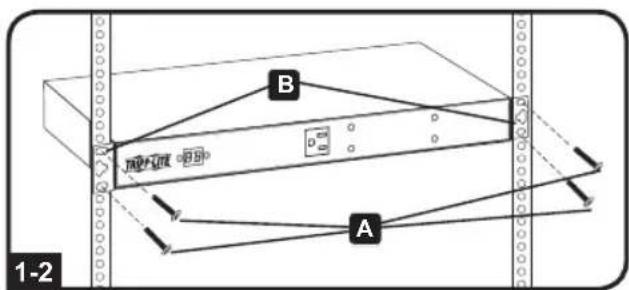
1U Rack Installation. Attach the PDU to the rack by inserting four usersupplied screws through the PDU mounting brackets and into the mounting holes of the rack rail as shown.
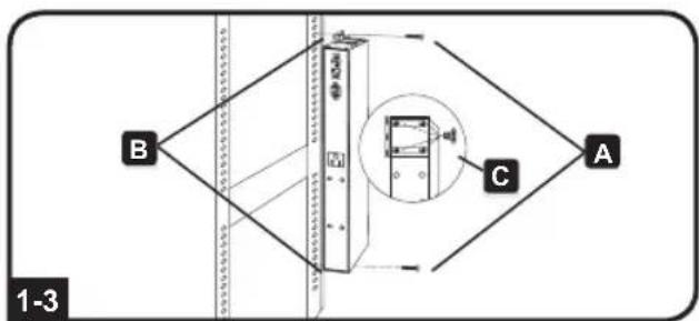
OU Rack Installation. Part 1: Remove the screws attaching the mounting brackets to the PDU, change the orientation of the brackets as shown and reattach the brackets. Use only the screws supplied by the manufacturer or their exact equivalent (#6-32, 1/4" flat head). Part 2: Attach the PDU vertically by inserting two or more user-supplied screws through the PDU mounting brackets and into mounting points in the rack or rack enclosure.
Installation
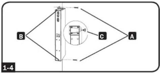
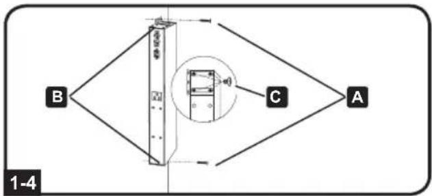
1-4 Wall Installation. After repeating Part 1 above, attach the PDU to a stable mounting surface by inserting two or more user-supplied screws A through the PDU mounting brackets B and into secure mounting points on the mounting surface.
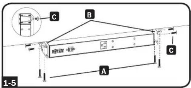
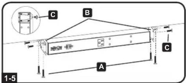
1-5 Under-Counter Installation. After repeating Part 1 above, attach the PDU to a stable mounting surface by inserting four user-supplied screws A through the PDU mounting brackets B and into secure mounting points on the mounting surface.
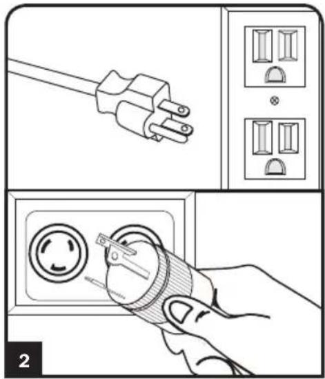
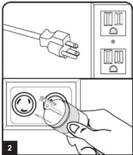
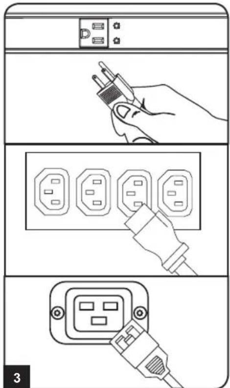
2 Attach the input plug of the PDU to a grounded outlet. Insert the plug directly into a grounded outlet that does not share a circuit with a heavy electrical load (such as an air conditioner or refrigerator).
Note: Select models include an input plug adapter that converts plug types for various applications. See 2-1 for details.
Installation
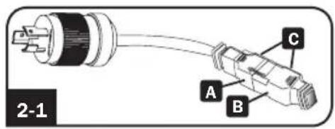
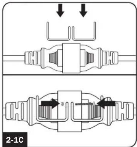
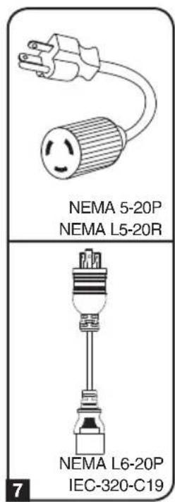
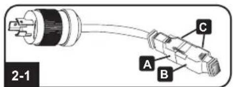
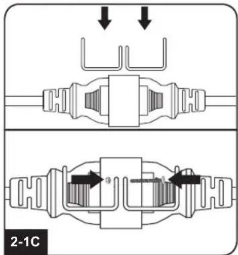
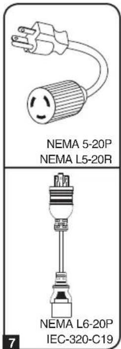
2-1 NEMA Adapter Connection (Optional - PDUMH20HV Only): The PDUMH20HV includes a plug adapter that adds a NEMA L6-20P plug to the input power cord. Use this adapter only if you will be connecting the PDUMH20HV to a NEMA L6-20R outlet. Insert the IEC 60320 C19 connector A of the adapter into the IEC 60320 C20 connector B of the input power cord. Secure the connection with the retention bracket C by using the included bolts to fasten the two halves of the bracket around the connection as shown.
Caution: To avoid the risk of electric shock, ensure that the Neutral (L2) conductor has been identified before connecting the PDU.
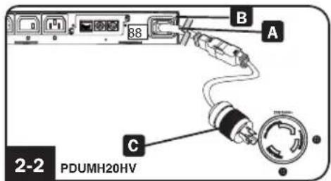
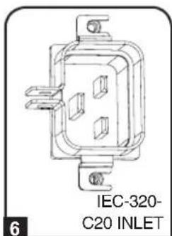
2-2 Input Power Cord Connection (PDUMH20HV Only): Insert the IEC 60320 C19 connector A of the input power cord into the IEC 60320 C20 inlet B of the PDU. Connect the other end of the input power cord C to a compatible source of AC power, such as a UPS system, PDU or utility outlet. The PDU should be provided with over-current protection. PDUMH20HV should be provided with a maximum 20A branch-rated over-current protection device.
Note: The AC power source should not share a circuit with a heavy electrical load (such as an air conditioner or refrigerator).
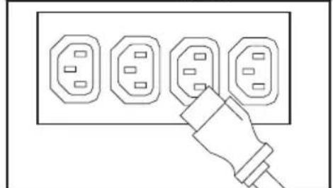
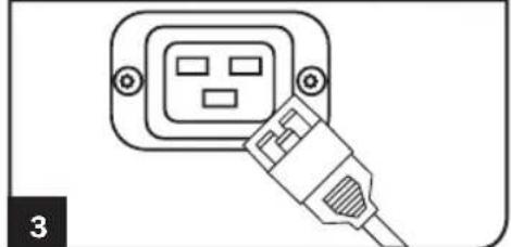
3 Attach equipment to the PDU. Do not exceed the load rating of the PDU. The total electrical current used by the PDU will be displayed on the digital meter in amperes.


Features
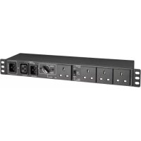
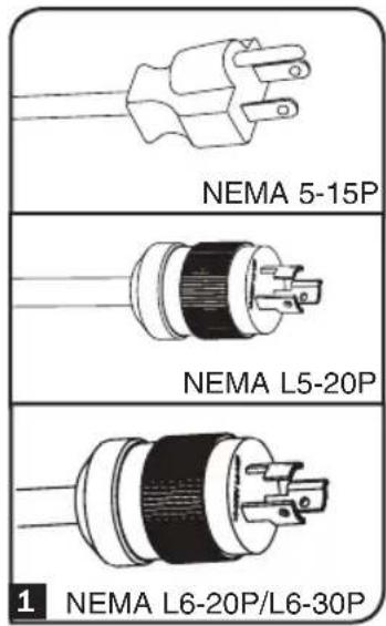
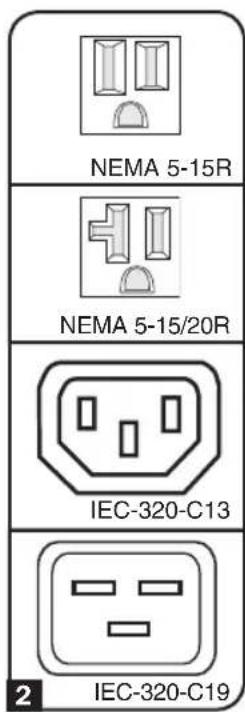
1 Input Plug (Varies by Model)
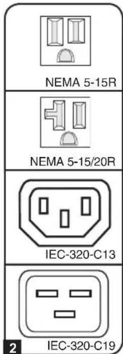
2 Outlets (Vary by Model): During normal operation, the outlets distribute AC power to connected equipment.
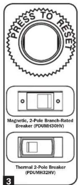
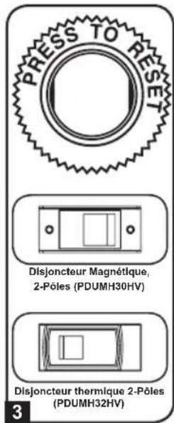
3 Circuit Breaker: If the current drawn by the equipment connected to the PDU exceeds the Maximum Load Rating, the circuit breaker will trip to prevent possible damage. When a circuit breaker trips, its plunger will pop up. Disconnect excess equipment and allow the breaker to cool at least one minute before depressing the plunger to reset the breaker.
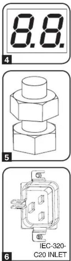
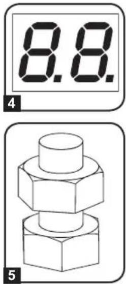
4 Ammeter: The total electrical current used by the PDU will be displayed on the digital meter in amperes.
5 Grounding Lug: Use this screw to connect the PDU to ground.
6 Power Inlet (Select Models): The IEC-320-C20 power inlet connects to the included power cord or a compatible user-supplied power cord. The inlet includes a bracket to secure the cord connection.
7 Input Plug Adapter (Select Models): Converts plug types for various applications.
Features
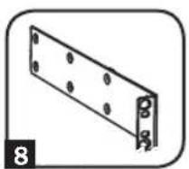

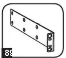
8 Longer 1U Mounting Brackets: Use these brackets to mount the 1U PDU horizontally in a standard rack or rack enclosure. The mounting depth can be adjusted by attaching the brackets to different positions on the PDU.
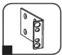
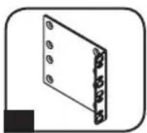
9 Shorter OU Mounting Brackets: Use these brackets to mount the PDU in a OU rack, wall or under-counter configuration for 1U PDU models.
10 2U Mounting Brackets: Use these brackets to mount the 2U PDU horizontally in a standard rack or rack enclosure, or in an under-counter configuration.
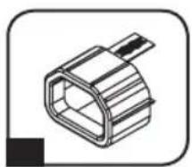
C14 Plug-Lock Insert Sleeve (Optional): Use the included plastic sleeves to secure C13 power cords to C14 inlets. Fit the sleeve over the end of the cord, making sure the pull-tabs remain outside the cord and the fit is secure. To unplug equipment properly, grip both the cord and the insert's tabs at the same time and pull.
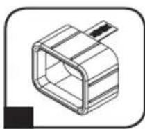
C20 Plug-Lock Insert Sleeve (Optional): Use the included plastic sleeves to secure C19 power cords to C20 inlets. Fit the sleeve over the end of the cord, making sure the pull-tabs remain outside the cord and the fit is secure. To unplug equipment properly, grip both the cord and the insert's tabs at the same time and pull.
Warranty & Warranty Registration
2-YEAR LIMITED WARRANTY
Seller warrants this product, if used in accordance with all applicable instructions, to be free from original defects in material and workmanship for a period of 2 years from the date of initial purchase. If the product should prove defective in material or workmanship within that period, Seller will repair or replace the product, in its sole discretion. Service under this Warranty can only be obtained by your delivering or shipping the product (with all shipping or delivery charges prepaid) to: Tripp Lite, 1111 W. 35th Street, Chicago, IL 60609 USA. Seller will pay return shipping charges. Visit www.triplite.com/support before sending any equipment back for repair.
THIS WARRANTY DOES NOT APPLY TO NORMAL WEAR OR TO DAMAGE RESULTING FROM ACCIDENT, MISUSE, ABUSE OR NEGLECT. SELLER MAKES NO EXPRESS WARRANTY OTHER THAN THE WARRANTY EXPRESSLY SET FORTH HEREIN. EXCEPT TO THE EXTENT PROHIBITED BY APPLICABLE LAW, ALL IMPLIED WARRANTYES, INCLUDING ALL WARRANTYES OF MERCHANTABILITY OR FITNESS, ARE LIMITED IN DURATION TO THE WARRANTY PERIOD SET FORTH ABOVE; AND THIS WARRANTY EXPRESSLY EXCULES ALL INCIDENTAL AND CONSEQUENTIAL DAMAGES. (Some states do not allow limitations on how long an implied warranty lasts, and some states do not allow the exclusion or limitation of incidental or consequential damages, so the above limitations or exclusions may not apply to you. This Warranty gives you specific legal rights, and you may have other rights which vary from jurisdiction to jurisdiction).
WARNING: The individual user should take care to determine prior to use whether this device is suitable, adequate or safe for the use intended. Since individual applications are subject to great variation, the manufacturer makes no representation or warranty as to the suitability or fitness of these devices for any specific application.
PRODUCT REGISTRATION
Visit www.triplite.com/warranty today to register your new Tripp Lite product. You'll be automatically entered into a drawing for a chance to win a FREE Tripp Lite product!*
- No purchase necessary. Void where prohibited. Some restrictions apply. See website for details.
FCC Notice, Class A
This device complies with part 15 of the FCC Rules. Operation is subject to the following two conditions: (1) This device may not cause harmful interference, and (2) this device must accept any interference received, including interference that may cause undesired operation.
Note: This equipment has been tested and found to comply with the limits for a Class A digital device, pursuant to part 15 of the FCC Rules. These limits are designed to provide reasonable protection against harmful interference when the equipment is operated in a commercial environment. This equipment generates, uses, and can radiate radio frequency energy and, if not installed and used in accordance with the instruction manual, may cause harmful interference to radio communications. Operation of this equipment in a residential area is likely to cause harmful interference in which case the user will be required to correct the interference at his own expense.
The user must use shielded cables and connectors with this equipment. Any changes or modifications to this equipment not expressly approved by Tripp Lite could void the user's authority to operate this equipment.
Regulatory Compliance Identification Numbers
For the purpose of regulatory compliance certifications and identification, your Tripp Lite product has been assigned a unique series number. The series number can be found on the product nameplate label, along with all required approval markings and information. When requesting compliance information for this product, always refer to the series number. The series number should not be confused with the marking name or model number of the product.
WEEE Compliance Information for Tripp Lite Customers and Recyclers (European Union)

Under the Waste Electrical and Electronic Equipment (WEEE) Directive and implementing regulations, when customers buy new electrical and electronic equipment from Tripp Lite they are entitled to:
- Send old equipment for recycling on a one-for-one, like-for-like basis (this varies depending on the country)
- Send the new equipment back for recycling when this ultimately becomes waste
Tripp Lite has a policy of continuous improvement. Specifications are subject to change without notice.


Manufacturing Excellence.
1111 W. 35th Street, Chicago, IL 60609 USA • www.triplite.com/support
1111 W. 35th Street, Chicago, IL 60609 USA • www.triplite.com/support
1111 W. 35th Street, Chicago, IL 60609 USA • www.triplite.com/support
1111 W. 35th Street, Chicago, IL 60609 USA • www.triplite.com/support
1111 W. 35th Street, Chicago, IL 60609 USA • www.triplite.com/support
PyKOBODCTBO noJIb3OBaTeJIa
1111 W. 35th Street, Chicago, IL 60609 USA • www.triplite.com/support
Copyright © 2019 Tripp Lite. Перениатka зanpencaetca.
ВаднIBLE указанноTekнcke 6e30napochtn
COXPAHNTE HACTOUIE YKA3AHNBA
HactoIeM pyKOBOcTBe COdePkaTcY k3aHn I npDeynpeXdHn, KOtOpbIe Heo6xOIMo Co6NIOaTb B npocece yCTaHOBKn, 3KcnnyatauHn XpaHeHn DaHHoro n3dEInn. rHopnpOBaHne 3TuX yKa3aHn n npDeynpeXdHn MoKeT pNBecTN K Notepe rapaHTnn Ha n3dEInne.

Baxkhble npedynpeXdeneHna
BIOK pacpepeHn nTaHn (PDU) yO6Ho OcHaue HecKOJIbKIMn po3eTKamn, Ho HE 0eocneuBaET 3aunTy NOcknoeHHoro 06OpyDobAHn OT Bbl6pOCOB HaprrKeHNn UWMOB B JINHM.
- BIOK paCnpedeHnna PDU) npEHa3NaueH ToIbKO IINcNoIb3OBAHnB 3aKpbTbIX NOMeHnX C peryInpuyEmbIM MKNPKoJIIMATOM BdaJN OT NCTOCHNKOB NOBbIeHHOH BNAxHOCTN, 3KCTpeMaJIbHbIX TEMHePaTYP, 3JIeKTpONPBOODhbIX 3aRpa3HTeNeI, nbIIN IN pIpMORO COJHeuHORO CBeta.
- PioidepKBAte TEMepaTyB03Dyxa BHyTpI NOMEeHnB DnaIa3OHe O T 0^ Do 50^
- YctaHObKa 6Ioka pacnpedeHnna PDU)doJIxHa npOn3BOIDtBCr TOLbKO KBaHmPPOBaHHbIM TEXHueCKM CneMaNCTOM.
He yctaHaBnBaIe 6Iok pacnpedeHnna (PDU) Ha He3aKpeHnHOHn HyeCToHBOB IOBepxHOCTN.
- YCTAHOBKY CNeDyET PpOIN3BOIDNTB COOTBETCTBUN C MECTHBIMN 3JIeKTPOTEXHueCKMN HOpMaMNI npaBnAMNI. O63aTeNBHO NcONb3yIte NOxODAUINE DJIY yCTaHABnBAeMOI CNTEmbl yCTpoiCTBa 3aUHTBI OT NpePpyOK NO TOKY B COOTBETCTBUN C HOMNHANMI, YKa3aHHbIMN Ha pa3bemax/ 06OpvIOBaHN.
- PiodkJIOUHTe 6IOK pacnpedeHnna (PDU) K PO3eTke, COOTBeCTBvUOe NpHrTbIM B Baue CTpaHe CTOPTeJIbHbIM HOpMaM N HaIpeXaUM O6pa3OM 3aUINuEHHOI OT N36bIToCHbIX TOKOB, KOOTKHX 3AmbKaHm N 3AmbKaHm Ha 3EMNIO.
3JNeKtpueeckne po3ETKn,peepes KOToPbIe OcyuEcTBnEeTcra 3JeKTPoNITaHHe o6OpyOBAHn,doJXHb6BtYCTAHOBnEHbBJIERKOIOCTVNHOM MeCTe B6n3n Hero.
He nodknoaTe 6Jok pacpepeJeHn nIra (PDU) K He3a3emneHHo po3eTke, a TaKke K VNDNHTEyM NII NEpEXOHNKAM. He IMeIOOM 3a3EmNHeHn.
-OB3aTeNbHO Ch6kaIte IIObIe MoIe, NOKJIIOuaEMble Hepa3bEMHbIM CnOCo6OM, NERKOIOCTyINHBIM JOKaJIbHbIM VCTPOINCTBOM 3aUNTHOTO OTKIOUOHeHIA.
- Hn B KOEM CJyuae He IPOIN3BOIDTe MOHTaX 3JNEKTPOOBOpyOBAHmBa BO Bpem rpo3bl.
- Tok, noTpe6IaEmbO TdJIbHbIMn 3JIeMeHTAMn O6OpyIOBaHn, NOKJIIOuAeMbIMn K 6JIOky pacnPpeJeHn nITaHn (PDU), He doJIxHe IpeBbIaTb HOMHaI COOTBeTCTByIOx p03eTOk 6JIOka pacnPpeJeHn nITaHn (PDU).
Cymmapna Harpy3ka, co3daabaemar noTpe6nteIaMn, nOdkHoueHHbIMK 6JIOky paCnpedeHn HNTAHN (PDU), He dojxHa IpeBbIaTb erO MaKcMaJIbHO DOYCTMHyHO Harpy3KV.
He BHOCTe N3MeHEnB KOHCTpyKUHO 6JOKa paCnpedeJeHnI PyTaHnI (PDU), BXoNbIx pa3bEmOB HnKabeJeNtAHnI.
- He BbICBepnBaIte OTBepCTn B KOpnyce 6noka pacnpdeJeHnna nTahnra (PDU) n He nbTaItecb BCKpbITb KaKyIO-nIOo erO qaCTb. BHVTn Hero HET DeTanei, OcCNYKBAeMbIX NOB3OBaTeJIem.
- He nCnoB3yIte 6noka paCnpedeHnna nTahnra (PDU) B cIyuae nobpejdeHnna IIObO n3 ero auctei.
He pekomehyetyncnoh3oBaHne daHHoro o6bpyoBaHnB CnCTeMaX Jx3Heo6ecneHn, rde erOBbIXoN 3cTPO npEiNoONKHTeBHO MOKeT pNBecTN K nepe6oM B pa6Ote o6OpdyoBaHnJx3Heo6ecneHn NIN B 3HaHTeBHO Mepe CHN3NTb ERO 6e3OnaCHOCTb INI 3d0fKeTNUBOCTb.
yctaHOBka
PpmeHne. YcToiCTBO, 306paKeHHoe Ha nIIOcTpaunx, MoKet HeCKoNbKO OTnuaTbcra OBaWe moDen PDU.
1 OnpeeneHne yctahOBouHoi KOHpyaun. Bnokn pacnpedeHn nHTan (PDU),
OINcBIAeMbIe B HAcToIeM pyKOBoDCTBe, MOrTy IcNoIb3OBaTbc8 B CneIyUoIx yCTaHOBOuHbIX KOHfNpyaunx: MOHTax B CTOnKy (2U, 1U n OU), HAcTeHHbIM MOHTax N MOHTax NOI npnlaBkOM. YcTaHOBOUYHe IcHfNpyaun, OTHOaIeC6K BaIeN KOHKpeTHO MoJeN, PpeIcTAbIeHb HnKe. Bbl6epnte Odn n3 TInOB KOHfNpyaun n CneIyIte Yka3aHnA M No yCTaHOBKe B COOTBE TCTBYUeM pa3dJe lara 1, noce yero nepexOAnTe K uary 2.
PpmeHne. He3aBnCIMo OT KOHpyaun yCTaHOBKn NOIb3OBaTeNb DOJXeH yCTaHOBNT npiroDnOCTb OCHactkn n ppeNoIraembIX npoceUp do HauJa MoHTaxa. BNOK paCnpedeJeHnna PtTAnH (PDU) nBXOJaA Bero KOMIIeK T OCHACTKa PpeHa3HaueHb I DaI O6blHbIX TINOB u KaΦOB u MOrTy He NdoXoNDt bIg BcEx ceNei npMeHeHry. YCTaHOBOHbIe KOHpyaun MOrTy pa3NJuATbcR B DetanJx.
1-1 YctaHOBka B WkaΦ BBICOTOn 2U.
PnKpEnIte NoCTaBnaEmbIe B KOMnJIekTe KPOHHTeHbIK 60KOBOI NaHeIN PDU npn NOMOu BNHTOB A u3 KOMnJIeKtA. Iocne yCTaHOBKn KPOHSTeHOB pa3MeCTInTe PDU B uKaΦy u 3aΦnKcnpyIte erO nyTEM BBepTbIBAHNue YeTbIpeX He BXoJxN X B KOMnJIeKT NOCTaBKn KpeNEXHbIX BNHTOB Upe3 KPOHHTeHbIB HAnpaBIAU Oue uKaΦa B
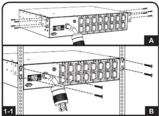
1-2 YctaHOBka B WkaΦ BBICOTOn 1U.
3akpenTe PDU B ukafy nytem BBepTbBaHnry YeTbIeX BHTOB A (He BXOJIuNX B KOMNJIeKT NocTaBKn) Upe3 MOHTaXHbIe KPOHtEiHbI PDU B MOHTaXHbIe OTBepCTnHa npabJIOUe IkaF, KaK noka3aHO Ha pucyHke.
1-3BepTKaJIbHa yCTaHOBka B uKaΦ
(0U).YacTb1:BbBepHnTe BnHTbI C,
obecneuBaOuNe KpeJIeHne
MOHTaXbIX KPOHtEiHOB K PDU,
N3MeHNTe NIOJoxHeNE KPOHtEiHOB,KaK
NOKa3aHO Ha pucyHKe, INpIKpeNTe
KPOHtEiHbHa IpexHHe MecTo.
NcNoIb3yIte TOnbKO BnHTbl,
NOCTabJIraEmble IpON3BOIDnteM, ININx
NOLHbI aHaIor (#6-32, 1/4" c NotaiHOH
rOIOBko).YacTb2:PiPKpenTe PDU
BepTKaJIbHO NyTEM BBepTbIBAHnA DByX
INN 6oJee BnHTOB A (He BXODaux X B
KOMJIeKT NOCTaBKn)Yepe3 MOHTaxHbIe
KPOHtEiHbPDU B MoHTaxHbIe
OTBepCTnA CTOnKn INN UkaΦa.
yctaHOBka
1-4 HacteHHbIM MoTax. Nocne nobTopeHnA DeiCTBn, ONHCaHHbIX BblSe B Yactn 1, npKpEnIte PDU K yctOuHBoM OHTaXHOIOBepxHOCTn IyTEM BBepTbIBaHn AByx INI60Jee BINTOB A (He BXODaIINX B KOMNJIeKT NOCTABKn) Chepe3 MOtaxHbIE KpoHITeHbI PDU B B MOHTaXHbIE OTBepCTnHa MOHTaXHOI NOBepxHOCTn.
1-5 MoNTaX IOI npINaBkOM. Nocne IOBTOpeHnI DeiCTBm, ONICAHbIX BblIe B Yactn 1, npKpEnITe PDU K yCTOuHBoM OHTaXHOIOBepxHOCTN IyTEM BBepTbIBaHnI YeTbIPex BINTOB A (He BXODAUX B KOMPNeKT NOCTABKN) Upe3 MOHTaXHbIe KpoHtEINbI PDU B B MOHTaXHbIe OTBepCTnHa MOHTaXHOI IOBepxHOCTN.
2 BkIIOUHTe 7tENTceJIbHbI pa3bEm BXoHoro Ka6JIa PDU B 3a3EmJehHyIO po3ETky 3JIeKTPnueckO cTeN. Pa3bEM CNEyET BkIIOuATb HENOCpeIcTBeHHO B 3a3EmJehHyIO po3ETKy, He HaxOJaIyOcB O6IeM KOHType C 60JIbIoI 3JIeKTPnueckO HaPy3KO (TAKO KAK KOHNIOHep IIN XoNOIDNBHK).
PpmeaHne. HeKOTOpbIe MoDeIIN KOMNKeTkyIOCTcpeXoHDHO BUNKO, pReO6pa3yIOueBxOHDHO pa3bEmDaHHoro TnPa Bpa3bEmbl DpyrNX TnNOB. POnpo6Hee cm.2-1
yctaHOBka
2-1 PdKnHue HnepeXoHnKa NEMA (He6aTeNbHO;ToIbKO dIy MoD.PDUHM20HV): MoeJIb PDUMH20HV ochaetaTcra WTeNCeJIb- nepeXoHnKOM, KOTOpBI oBeCneuBaET uHyp nITAHnI IOnOJIHnTEJbHbIM pa3bEmOM TnA NEMA L6-20P. 3TOI nepeXoHnK CneUye NTcNOJIb3OBaTB ToIbKO npI POnKJIIOUeHHN yCTpoiCtBA moEJI NPDUMH20HV K po3eTke TnA NEMA L6-20R. BCTaBbTe pa3bEm IEC 60320 C19 A nepeXoHnKa B pa3bEm IEC 60320 C20 B BXoHOrO UHypa NITAHnI. 3aФNKcnpYte COeINHeHne pni NOMouIz 3axmOB dIy φnkCaunn Ka6eJIg C nCNoJIb3OBAHnEM BXoJaIUX B KOMIIKeKT BoNTOB, CKpeJIraHOUIx DBe Yactn 3axmua BOKpyr pa3bema, KaK nOKa3aHO Ha pncyHke.
BHHMaHHe! Bo n36exaHne onachocTH nopaxeHn 3JIeKTPnueckm TOKOM Heo6xOdmo pacno3HaTb HeItpaIbHbI npOBod (L2) nepeD noDKNoyeHnEm PDU.
2-2 POnKnHoyHe BxOHDoro WHypa NtAHn (ToIbko 1nmao.PDUMH20HV):BCTaBBte pa3bem IEC 60320 C19 A BxOHO RO WHypa NtAHn BO BxOHOH pa3bem Tnna IEC 60320 C20 B6noKa pacnpedeHn HHTAHn (PDU).POnKnIOHTe Dpyro KOHeu BxOHO RO WHypa NtAHn C KO CBMeCTHMOMy IVCTOHky NITAHn NEpeMeHHORo TOKa (Hanpimep, INP, PDU nPi po3eTke 3JIeKTPuecko CETn).PDU DOJnxEh 6blb OCHaUeH 3aunTOIOT Neperpy3OK NO TOKY. YcTPOINCTBO PDUMH20HV DoJXHo OCHaUaTbcr yCTPOINCTBOM 3aunTbI OT neperpy3OK NO TOKY HOMHaIOM He 6oJee 20A.
PpmeHn. HcOHTbB OObIe KOHTpe C BoJbWOn 3JIeKTPuecko Harpy3Ko (TakO KaK KOHduHep nn XOIOJIbHKn).
3 Pooknoute o6opyobahnke PDU. He npebblaTe HOMHaJIbHyO Harpzky PDU. CymMapHbI 3neKtpnueckn ToK, nTope6Jembl PDU, BbcBeyBaetcHa HNDkatope UΦpoBOr0 N3MepuTeJI B aMnepax.

XapakTepeNCTnKn npOdyKta
1 BxOHOH pa3bem (B 3aBcHMOCTN OT MOeHN)
2 Po3eTkn (B 3aBncmocn OT moDenn): B uTaTHOM pexHMe pa6oTb1 po3eTKn pacnPepdEJIHO T MOUHOCTb nepEmEHORO TOKa MEXy IIOKIIQUeHHbIM K HIM 3IeMeHTAMN O6OpYDoBaHn.
3 ABTomatueckn BbIKIOaTeIb: ecNI TOK, notpe6JIeMbI o6opyoBaHHeM, NOkIIOUeHHbIM K PDU, npeBbIaET erO MAKcImaJIbHO DOyCTmHy HO Harpy3KY, To npOnCXODIT cpaBaTbIBaHne ABTomATueCKORO BbIKIOuAteIe BO 36ExaHne BO3MOXHO RBOxOda O6opyoBaHnI N3 CTPO. PnCp6aTaBHaHN ABTomATueCKORO BbIKIOuTeJI eRO KHONKa BBICKaKINBaET BBepx. Pepei C6pocOM ABTomATueCKORO BbIKIOuAteIe HaxaTHeM KONKn CNeDyET OTCoEINHTb O6opyoBaHne, CO3dAnUe ee N3bTOUYHO Harpy3KY, IN DaTb BbIKIOuAteJIIO BO3MOXHOCTb OXNaINTbcr B TeueHne OJHOH MNHyTbl.
4 Amnepmetp: cymMaphBn 3JNeKtpueckn TOK, nOtnpe6Jnembl PDU, BbICBeHNBaETcHa HnDnKaTope UΦpoBOrO N3MepntJI B aMnepax.
5 KneMa 3a3eMJIeHn: 3a3eMJIInTe PDU c nIOMOJIbIO 3TOrO BnHTa.
6 Bxodno pa3bem nHTAHN (Dn oTdeNbHbIX MoJeN): BXoHOJ pa3bem nHTAHN IEC-320-C20 NOKJIIOHaETcK NocTABnEMOMY B KOMnIeKTe WHypy nHTAHN INN K npNo6peTaEMOMY OTeNbHO WHypy nHTAHN, COBmecTMOMY C HIM. Jn FkCaun NoCoEduHeHOrO Whpy nHTAHN BxOHNO pa3bem OCHaUeH CneuaNBbHM KPOHUTeHOM.
7 NepexoHnK BxOHorO pa3bema (IJIa OTdEhBbIX MoDenei): npeo6pa3yET BXoHoi pa3bEm DaHHoro Tnna B pa3bemblpyrN X TINOB.
XapakTepeNCTnKN npOdyKta


8 YdHHeHbIe MoHTaXHbIe KPOHTeHHbI pa3Mepom 1U: nCnOJIb3yIte 3TN KPOHTeHHbI dIra roPn3oHTaJIbHO MOHTaXa PDU pa3Mepom 1U B CTaHApTHyO CToKy IINu IkaΦ. MoHTaXHa rJy6Ha MoKeT peYInpOBaTcB cyTEM KpeIIeHna KPOHTeHOB KdpYm TOcKaM PDU.
9 YKOpOeHHbIe MOHTaXHbIe KPOHtEINHbI dIe BepTnKaJIbHOrO MoHTaxa: NcNoIb3yIte 3TN KPOHtEINHbI dIe BepTnKaJIbHOrO MoHTaxa PDU B cToIky (0U), a TaIOKe Ha cTeHy nII nOd npInaBOK (dIra moDeIe PDU BBICOTOn 1U).
MOHTaXHbIe KPOHtEiHbI pa3Mepom 2U: nCNoJIb3yIte 3TN KPOHtEiHbI dIg rOpN3OHTaJIbHOrOMOHTaKa PDU pa3Mepom 2U B cTaNdApTHyIO CTOnKy IIN NkAq Jn6o dIg MoHTaKa NOI npNJAbKOM.
11 MyfTa pa3bema C14 (onu): 3aФнксуIe pa3bembl B po3eTKax npn NOMOu BXODaHX B KOMNtK TnactMaCCOBbIX MyfT nOd pa3bembl C14. PnIKpeNTe MyfTy K pa3bemy, y6eINBunCb B TOM, YTO ee r3bUKN OCTaOTc3 a PneJeIaMn pa3bema n IIOTHo PnIneraOT K Hemy. JnI npaBnHoro OTCoeDHeHnO obOpyIDOBaHnCneDyET BblHMAtb pa3bem C MyfToiN 3po3eTKn, DePjAc6 3a Ra3bUKN.
12 Myfpa pa3bema C20 (onu): 3aФнкpyte pa3bembl po3eTKax npn nOMOu BXODaHX B KOMPJIeK TIIaCTMaCCOBbIX MyfT NOd pa3bembl C20. PpIKpeNITe MyfTy K pa3bemy, y6eINBUnCb B TOM, YTO ee r3bUKN OCTaHOTc 3a IpeIeIaMn pa3bema N IIOTHO pIINERAOT K HEMy.ДЯп павиьHorO OTCoeDInHeHry O6OpYIOBaHry CNeDyET BblHMAtb pa3bEm C MyfToi n3 po3eTKn, Depxacb 3a Ra3bUKN.
ГараHTиньie obaTeIbCTBa
OrpaHnueHHa rapaHTna 2 roD
TRIPP LITE rapaHTnpyET OTCYCTBNE DepeKTOB MaTePnaIOB N 13ROTOBHe B TeHeHne OJHO 2 rOc MmEHTa nepBOHaayIbHOI NOkTN. O63aTeJIbCTBA KOMnAHn TRIPP LITE no HactoJe rapaHTn ORpaHUNBaOTcpeMOHt mIIN 3AmEHn (no ee eDInHOJNUHOMy yCMOTpeHIO) IIObIX TAKNX DepeKTHbIX N3DeN. DnI NOUYeHHN ycNyr no daHHoR rapaHTn HeOBxOJIMNo NOnyUHbHomep Returneded Material Authorization (RMA - pa3peSeHne Ha BO3Bpat MaTePnaIOB) OT KOMnAHn TRIPP LITE nIN ee ABTopu3OBAHHORo cepBCHORo CEHTpa. N3DeNn DOJXHb6bTb BO3BpaueHb B KOMnAHn TRIPP LITE nIN abTopu3OBAHHb CepBCHbIeHTP TRIPP LITE c npdeONlato TpaHCnOpTbIX pacXODOB IN COPOBQKaTbCRA KpATKIM ONICAHMeB O3HNKSeI np6JIeMbI NOKUMeHOM, NOITBePckJaOUsM DaTy N MeCTO erO npNO6peTHeN. DeiCTBne HactoJe rapaHTn He pacnPoCTpaHReTcH a O6OpUdOBaHHe, NOBpeJDeHoe B pe3yNbTaTe abAPIN, He6peXHOrO obpaueHHe NIN HEPaBnIBHOrO NCIOBAAHn, a TAKKe BnDOImMeHEHHeK KaKM 6b To HN 6blIO 6bpa3OM.
3A NCKJIIOUOHEHEM INPEYCMOTPEHHbIX 3DECb CIIyAEB KOMNAHNA TRIPP LITE HE INPEIOCTABJIAET KAKNX-ⅡIbO RAHbIX INIIN IOPA3UMEBAEMbIX IAPAHTN, BKIOUAYA IAPAHTN KOMMEPCHKO INPIROHOCTN INIPIROHOCTN INIA KAKOI-ⅡIbO KOHKPETHO LCEIN. B HeKoTObIX Wtatax/rocydapcTBax ORpaHueHne INI INCKIOUOHe HIOpa3UMeBAEMbIX rapaHTN He DOnyckaTc; cNeIOBaTeJIbHO, Bblweyka3aHHe(-bie) ORpaHueHne(-) INI INCKIOUHe(-) MOrT He paNpocTaHrbc Ha NOKyntela.
3A NCKIIOUCHENEM INPEDYCMOTPEHHbIX BblIE CNyAAEB KOMNAHRA TRIPP LITE HN INPNKAKNXOBCTOATEBCTBAX HE HECET OTBETCTBEHHOCHTN 3A INPRMbIE, KOCBEHHbIE, CNYAHHBIE ININIOBOUYbIKN IIN60 YbBITKN, ONPENEJIeMBeI EOCbIMN OCBCTOATENBCTBAMN, BO3HNKAIOUIBEBCB3N C INCNOJB3OBAHNE DAHHOI N3DEJIN, DAXE B CNYAE EE INHOPMPOBAHNAOBO3MOXHOCTN HACTYNIIEHNA TAKNX YbBITKOB. B qactHOCTN, KOMNAHRA TRIPP LITE He Hecet OTBETCTBEHHOCNT3a KaKne-Ⅱn6 n3deppkKn, TaKne KaK ynyueHHbIe npnbbln nIN DoXoDbI, NoTepr obopydoBaHnra, NoTepr BO3MOXHOCTNNCNoB3OBAHNa OBOpDobAHnra, NoTepr nporpammH.
IeHTnФнkaUHbIe HOMepa, CBnTeJIbCTByIOuIe O COOTBETCTBnHOPMaTHNBHbIM Tpe6OBAHnM
C ueIbIO nIeHTnHnkaUIN, a taKke cepTnHnkaUIN COOTBETCTBnH HOpMaTHNBtM Tpe6oBaHnM, pInO6peTeHOMy Bamn n3dJIIO KOMPAnHH Tripp Lite npncBoEH yHKaJIbHbN CEpIHbH Homep. CepIHbH Homep, BmecTe Co BCEn He05xOIMOn IHΦopMaUne I MapKnPOBkAMn 6 Odo6peHH, yKa3aH Ha rplbke N3rTOBHTeR, npKpePteHHOM K n3dJIIO. Ppi 3anPoCe IHΦopMaUIN O COOTBETCTBnH HopMaTHNBtM Tpe6oBaHnM BcERda COo6uaTe CEpIHbH Homep n3dJIIN. He cJeNyET nYtaTb cepHIbH Homep C MapKo INI HOMep MoeJI IN3dJIIN.
HΦopmaunn dnn KIneHTOB KOMNaHN Tripp Lite o co6IIODeHHN Tpe6oBaHn AnpeKTHBbE C 06 otXoJax 3neKtpnueckoro n 3neKtpoHHoro 6OpdyobAHn (WEEE)

Corlacho DnapeKtue EC 06 oTxOax 3neKtpueckoro n 3neKtpoHoro 6bOpydoBaHna (WEEE) npimMeHmbl HopMaB CnyaX, KOrda NOKynatei npno6petaOT HOoe 3neKtpueckoe n 3neKtpoHoe 6bOpydoBaHne kOMpaHn Tripp Lite, OHN IMeIOT npabo Ha cnedyuopee:
- OtnpaHbI)
- OtnpaBky HOBOrO obOpyIDobAHnO dbaTHo Ha yTIN3aUH, KOrDa OHO B KOHeHOM ITORE cTAHOBTcN3HOWeHHbIM
KomnaHn Tripp Lite nocToHHo COBepueHCTBye T CBOIO npOyKuHO. B CBa3N c 3TMM BO3MOXHO u3MeHeHne TexHuecknx XapakTePncTk 6e3 npDbaPntelHo r yBeOMJeHn.


PpOyKnBbHcEe
1111 W. 35th Street, Chicago, IL 60609 USA • www.triplite.com/support
Benutzerhandbuch
1111 W. 35th Street, Chicago, IL 60609 USA • www.triplite.com/support

Manufacturing Excellence.
1111 W. 35th Street, Chicago, IL 60609 USA • www.triplite.com/support