SmartRack SRCOOL60KCW - Air Conditioning Tripp Lite - Free user manual and instructions
Find the device manual for free SmartRack SRCOOL60KCW Tripp Lite in PDF.
| Product Type | Precision In-Row Water Cooler |
| Brand | Tripp Lite |
| Model | SmartRack SRCOOL60KCW |
| Category | Air Conditioning |
| Dimensions (W x D x H) | 300 x 1090 x 2000 mm (12 x 43 x 79 in) |
| Net Weight | 187 kg (412 lb) |
| Power Supply | 1~, 50/60 Hz, 208-230 V ±10% |
| Max Power Consumption | 2.41 kW |
| Nominal Cooling Capacity | 43.4 kW |
| Max Cooling Capacity | 59.1 kW |
| Air Flow | 7500 m³/h |
| Nominal Chilled Water Flow | 80 Lpm |
| Condensate Pump (optional) | Flow: 5 L/h, vertical lift: 5 m (16 ft) |
| Display | LCD 64 x 128 pixels, 4 LED indicators |
| Temperature Control | Intelligent (PID) with built-in microcontroller |
| Network Interfaces | Web/SNMP (RJ45), RS-232/485, CAN ports |
| Water Leak Detection | 4 m cable (configurable up to 50 m) |
| Fans | 8 multi-speed fans, hot-swappable |
| Security | Lockable doors, audible alarm, dry contacts, emergency stop |
| Maintenance | Washable filters, quarterly condensate pan cleaning |
| Warranty | 2 years (1 year outside USA/Canada/Mexico) |
Frequently Asked Questions - SmartRack SRCOOL60KCW Tripp Lite
User questions about SmartRack SRCOOL60KCW Tripp Lite
0 question about this device. Answer the ones you know or ask your own.
Ask a new question about this device
Download the instructions for your Air Conditioning in PDF format for free! Find your manual SmartRack SRCOOL60KCW - Tripp Lite and take your electronic device back in hand. On this page are published all the documents necessary for the use of your device. SmartRack SRCOOL60KCW by Tripp Lite.
USER MANUAL SmartRack SRCOOL60KCW Tripp Lite
In-Row Precision Chilled Water cooler
Espanol. 60
Francais. 119
Pycckn 178
PROTECT YOUR INVESTMENT!
Register your product for quicker service and ultimate peace of mind.
You could also win an IS0BAR6ULTRA surge protector—a $100 value!
www.triplite.com/warranty


Manufacturing
Excellence
1111 W. 35th Street, Chicago, IL 60609 USA www.triplite.com/support
Copyright © 2016 Tripp Lite. All rights reserved.
Table of Contents
1. Important Safety Instructions 3
1.1 PlacementWarnings.. 3
1.2 Connection Warnings 3
1.3 UsageWarnings 3
2. Introduction 4
2.1 Product Introduction 4
2.2 Functions and Features 4
2.3 Packing List 5
2.4 Appearance 6
2.5 Component Identification 6
2.6 Piping System.. 8
2.7 Control Panel.. 8
2.8 Network Interface.. 9
3.Installation 10
3.1 Installation Site 10
3.2 Placement 10
3.3 Handling 11
3.4 Positioning. 11
3.5 Side Panel Removal. 13
3.6 Drilling Holes 14
3.7 External Piping 15
3.8 Power Connection 16
3.8.1 Power 16
3.8.2 Condensed Water Pipe 19
3.8.3 Control Box 19
4. Initial Startup 20
4.1 Pre-Startup Inspection 20
4.2 Power Supply 20
4.3 Coolant Line Purge 21
4.4 Operating Temperature and Humidity 22
4.5 Water Leakage Detector 23
4.6 Water Balance 23
4.7 PID Setting 24
5. Operation 26
5.1 LCD Hierarchy.. 26
5.2 Control Panel Operation 27
5.3 Status Screen and Main Menu 27
5.4 Account Authority and Login 28
5.5 Operation Modes 28
5.6 Shutdown 29
5.7 Cooling Unit Settings 29
5.7.1 Set Point 29
5.7.2 Local Setting 29
5.7.3 Controller Setting 31
5.7.4 Alarm Setting 31
5.7.5 View System Status 32
5.7.6 View/Reset Running Hours 33
5.7.7 View / Clear Event Log.. 33
5.7.8 Changing System Type 33
5.7.9 Restoring Default Settings 34
5.7.10 Setting Automatic Control Mode 34
6. Network Configuration 35
6.1 SNMP Configuration 35
6.1.1 Configuring via Web-Based Interface....36
6.1.2 Configuring with TLNET (System) 37 Configurator
6.1.3 Configuring via Telnet 38
6.1.4 Configuring through COM Port 39
6.1.5 Configuring via Text Mode 40
7. Precision Cooling Dashboard Software 43
7.1 Monitor 43
7.1.1 Status and Information. 43
7.1.2 History 44
7.2 System 45
7.2.1 Administration 45
7.2.2 Notification 49
8. Optional Accessories 52
9. Maintenance and Cleaning 52
9.1 Firmware Upgrade 52
9.2 Storage 52
10: Troubleshooting 53
Appendix 1: Technical Specifications......56
Appendix 2: Periodic Inspection / 57 Maintenance List
Appendix 3: Glycol Correction Table ....59
Appendix 4: Warranty and Product Registration
1. Important Safety Instructions
SAVE THESE INSTRUCTIONS
This manual contains instructions and warnings that should be followed during the installation, operation, and storage of this product. Failure to heed these instructions and warnings may affect the product warranty.
1.1 PlacementWarnings
Carefully read the manual before any installation, operation, and maintenance. To avoid personal injury and equipment damage, be sure to operate the product in accordance with the instructions in this manual and the markings on the product.
Never move the unit alone. Always use an assistant.
When handling the equipment, take into account the unit's height and center of gravity. Only lift the unit from the bottom.
1.2 ConnectionWarnings
The unit can be connected with a single or dual power source. Make sure the input power is disconnected before making a connection. If necessary, use a multi-meter to confirm this.
Do not install the equipment on a flammable or unstable floor.
This unit is only intended for indoor use. The indoor environment must be separate from the outside air to avoid temperature and humidity interference. Consult your national or local regulations for separating the installation environment.
A cable connected to this equipment must meet applicable NEC and network communications cabling standards. As appropriate, all wiring and equipment should be installed in accordance with NFPA 70 National Electrical Code and the applicable sections of ANSI C2 National Electrical Safety Code.
The equipment is designed for altitudes up to and including 2000 m (6560 ft.) above sea level.
The equipment is intended to be installed by a service person and in a Restricted Access Location only.
The unit's grounding wires must be effectively connected with the grounding system.
1.3 UsageWarnings
High voltage may be fatal! The internal components may have hidden dangers, and only qualified service personnel should service the unit. Improper operation may lead to serious injury, death, or equipment damage. Be sure to follow all instructions and warnings contained in this manual.
When replacing the side panels, front door, or rear doors, make sure there is no foreign matter in the cabinet.
Use of this equipment in life support applications where failure of this equipment can reasonably be expected to cause the failure of the life support equipment or to significantly affect its safety or effectiveness is not recommended.
The unit contains moving components. Keep arms, legs, hair, clothes or jewelry away from unit during operation.
2. Introduction
2.1 Product Introduction
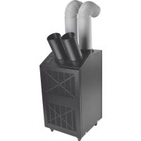
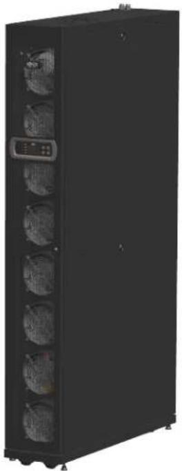
The Tripp Lite SRCOOL60KCW In-Row Precision Chilled Water Heater uses a modular, parallel cabinet design that facilitates expansion or movement and can be flexibly integrated into your data center environment. With a high cooling efficiency and the ability to be set in an area adjacent to a heat load, the SRCOOL60KCW decreases ambient temperature in order to lower overall energy costs and prolong equipment lifespan. As your data center grows, your increased cooling needs can be met by easy re-configuration of the equipment.
When installed in a data center, untreated air will be drawn in from the rear of the cooling unit and treated and cool air will be released from the front of the unit.
The cooling unit is managed by a user-friendly interface. Cooling efficiency can be actively controlled with the built-in microcontroller unit that reports abnormalities via the alarm system.
2.2 Functions and Features
Intelligent temperature control
Built-in microcontroller unit accurately detects and manages the data center's temperature, automatically adjusts the unit's output, and supports two automatic control modes, intelligent control mode (default) and PID control mode.
User-friendly control interface
Provides easy setting, monitoring, and access to system configuration and status.
Three-way ball valve automatic spring-resetting
During an abnormal power interruption, the inner flow-rate actuator will automatically close the three-way ball valve within 15 seconds to stop chilled water from continuously flowing into the coil and generating condensation, which may lead to water leakage.
Upper piping configuration option
Supports lower (default configuration) and upper (with SRC0OL60KTP kit, sold separately) piping for a flexible configuration.
Afarm system
Detects abnormalities and reports via a buzzer, an external dry contact device, or over the TCP/IP connection.
Heat load temperature detection
Accurately monitors the heat load temperature via remote temperature sensors.
Water leakage detection
Optional water leakage detector (configurable up to 50m / 164 ft.) immediately informs the user of any water leakage.
Output and input dry contacts
Includes two output and two input dry contacts for fire alarm, smoke alarm, system alarm, etc.
Insulated side panels
Isolates the unit from outside temperature variations.
Multi-speed and hot-swappable fans
The unit is equipped with high efficiency and energy saving fans whose rotation speed is adjustable between 30 100% . Fans are hotswappable for uninterrupted unit operation.
Lockable front / rear doors and side panels
Prevents unauthorized access.
Condensed water pump
The condensed water pump automatically drains condensed water while the water level sensor at the bottom of the cabinet detects the condensed water pan's respective water level to avoid leakage.
Clusters
Offer convenient movement or relocation.
Network interface
Provides remote monitoring and management through SNMP protocol.
2. Introduction
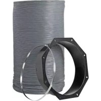
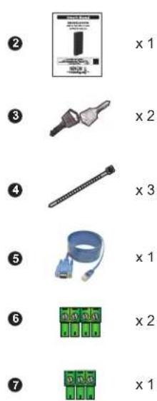
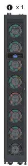
2.3 Packing List

| No. Description Quantity | ||
| 1 | Tripp Lite SRCOOL60KCW In-Row Precision Chilled Water cooler 1 | |
| 2 | Owner's Manual 1 | |
| 3 | Key (for use with front / rear doors and side panels) 2 | |
| 4 | Cable Tie 3 | |
| 5 | RJ45 to DB9 Cable 1 | |
| 6 | 4-pin Terminal Block 2 | |
| 7 | 3-pin Terminal Block 1 | |
| 8 | 2.8 mm Hex Wrench 1 | |
| 9 | Cable Gland 2 | |
| 10 | Communication Wiring Duct Cover Plate 2 | |
| 11 | Power Supply Cover Plate 1 | |
2. Introduction
2.4 Appearance
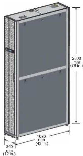
(Figure 2-1: Appearance and dimensions)
2.5 Component Identification
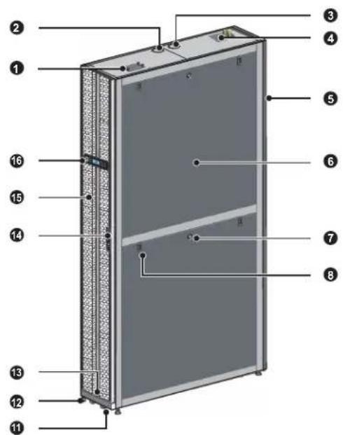
External
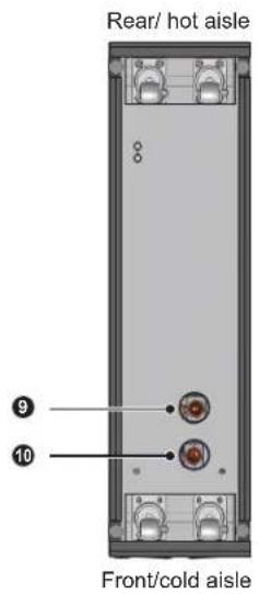
(Figure 2-2: Front view) (Figure 2-3: Bottom view)
| No. | Description |
| 1 | Wiring access |
| 2 | Upper outlet access |
| 3 | Upper inlet access |
| 4 | Input power terminal block |
| 5 | Removable rear door |
| 6 | Removable, insulated side panel |
| No. | Description |
| 7 | Side panel lock |
| 8 | Side panel latch |
| 9 | Lower inlet access |
| 10 | Lower outlet access |
| 11 | Casters |
| 12 | Levelers |
| No. Description | |
| 13 | Level |
| 14 | Front door lock |
| 15 | Front door |
| 16 | Control panel |
2. Introduction
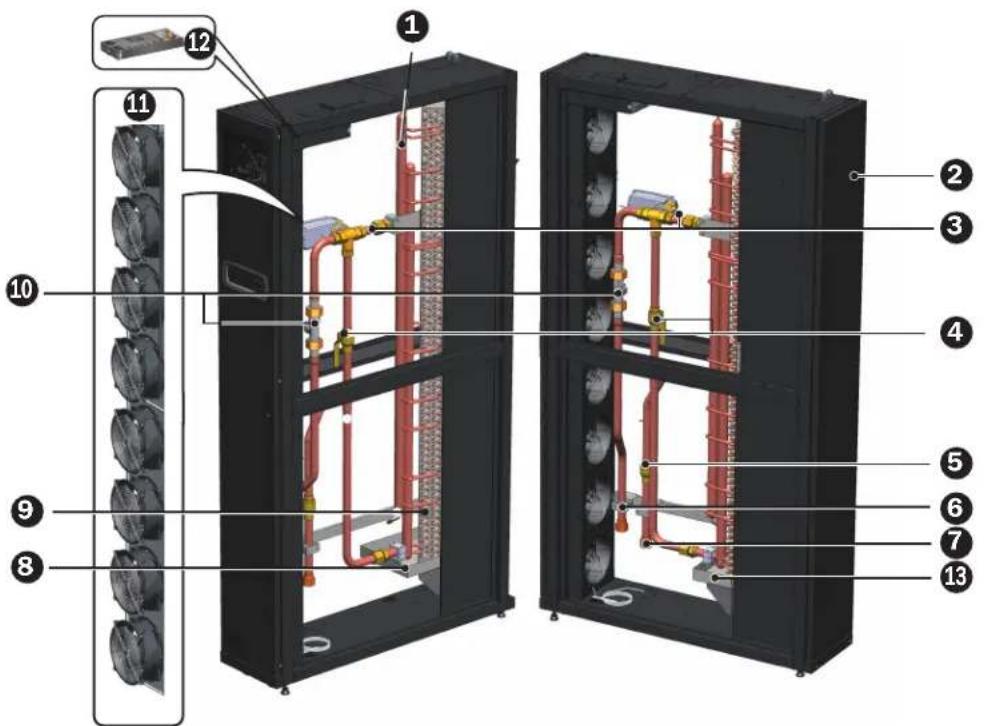
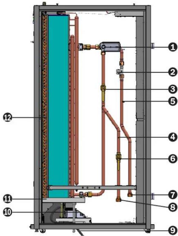
Internal
(Figure 2-4: Internal components)
| No. | Description |
| 1 | Outlet water pipe manual exhaust valve |
| 2 | Filters* |
| 3 | Three-way ball valve and actuator |
| 4 | Bypass valve |
| No. | Description |
| 5 | Inlet shut-off valve |
| 6 | Outlet connector** |
| 7 | Inlet connector** |
| 8 | Condensed water pan |
| 9 | Coils |
| No. | Description |
| 10 | Flow meter |
| 11 | Fans |
| 12 | Power supply unit (each on front- and rear-side of unit) |
| 13 | Level switch (located in water pan) |
Always use compatible washable aluminum filters (MERV1, ASHRAE 52.2).
* Each of the 6 7 connectors is a 25 mm (1 in.) PT female connector.
2. Introduction
2.6 Piping System
(Figure 2-5: Pipe circuit diagram)
| No. | Description |
| 1 | Three-way ball valve and actuator |
| 2 | Flow meter |
| 3 | Bypass valve |
| 4 | Inlet water temperature sensor |
| No. | Description |
| 5 | Outlet water temperature sensor |
| 6 | Inlet shutoff valve |
| 7 | Outlet connector |
| 8 | Inlet connector |
| No. Description | |
| 9 | Condensed water drain pipe |
| 10 | Condensed water pump |
| 11 | Condensed water pan |
| 12 | Coils |
2.7 Control Panel
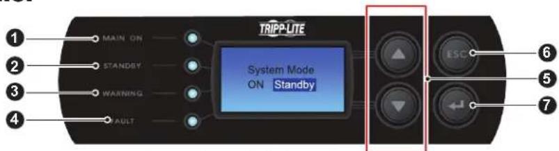
(Figure 2-6: Control panel)
| No. Item Description | |
| 1 | MAIN ON The green LED indicates power-on. When flashing, indicates the unit is in installation mode. |
| 2 | STANDBY The yellow LED indicates the unit is running in standby mode. When flashing, indicates the unit is running in force mode. |
| 3 | WARNING The yellow LED indicates alarm information. |
| 4 | FAULT The red LED indicates fault information. |
| 5 | ▲ / ▼ Goes back to previous screen or moves up to next screen / Moves up or down / Increases or decrease number. |
| 6 | ESC Goes back to previous screen or cancels current operation. |
| 7 | ← Enters your selected item or confirms your selection or setting. |
2. Introduction
2.8 Network Interface
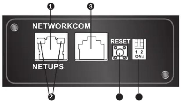
Network Port: Connects to the Ethernet Network.
LED Indicators: When the interface is initializing, the two LED indicators simultaneously flash to show its status.
Rapid simultaneous flashing (every 50ms): Initialization in progress.
- Slow simultaneous flashing (every 500ms): Initialization failed.
WARNING: Do NOT disconnect the cooling unit's input power during initialization. This could result in data loss or damage to the network interface.
The green (left) LED indicator shows the network connection status:
- ON: Network connection established and the IPv4 address is useable.
- OFF: Not connected to a network.
- Flashes slowly (every 500ms): Faulty IP address.
The yellow (right) LED indicator shows the linking status between the interface and the system:
- Flashes rapidly (every 50ms): Communication established.
- Flashes slowly (every 500ms): No communication.
3 Console (COM) Port:
- Connects to a workstation with the provided RJ45 to DB9 cable for system configuration.
- Connects a TLNETEM environmental monitoring device (optional).
Reset Button: Resets the interface. This does not affect the operation of the cooling unit.
DIP Switches: Set up operation modes.
| DIP Switches Operation Mode Description | ||
| 1 2 ON | Normal Mode Provides the coo | ing unit's status information and parameters over the network. |
| 1 2 ON | Pass Through Mode | Stops polling the cooling unit but transfers the communication data between the console port and the cooling unit. |
| 1 2 ON | Sensor Mode (with TLNETEM) | Collects data from an optional TLNETEM. It provides not only the cooling unit's status and parameters, but also the TLNETEM's status information and environmental parameters. |
| 1 2 ON | Configuration Mode | In this mode, the user can login through the console port and configure the interface's settings. |
3. Installation

WARNING:
- Only service personnel should perform the following installation procedures. To avoid equipment damage and personal injury, do not perform unauthorized installation, piping or handling.
- The equipment's high voltage is potentially fatal! Only qualified service personnel should access inner components or perform wiring.
3.1 Installation Site
When planning the cooling unit's installation site, consider the following for the best efficiency.
Environmental requirements: The installation site must allow the equipment to move in and out, the flooring must bear the weight of the equipment and there must be sufficient space for maintenance, operation, and pipe repair. The cooling unit can only be located indoors. The indoor environment must be isolated from the outside air to avoid temperature and humidity interference. Outside humidity entry must be minimized in accordance with local or national regulations to avoid the increase of operating costs due to loss of cooling capacity.
Humidity and heat source: Implement waterproofing and heat insulation engineering for the indoor environment to isolate the unit from outside hot, humid air.
Note: The unit cannot humidify or automatically de-humidify. If the humidity of the installation environment exceeds the operational scope (refer to 4.4 Operating Temperature and Humidity), the condensation of the water in the coil may lead to a rise in the water level of the condensed water pan, triggering an alarm.
Noise impact: During maximum output, the operation of this cooling unit may produce fan noise in excess of 60 dB. Therefore, it is not suitable to install the unit close to offices.
Input power: In connecting the power supply, ensure the power conforms to the rated value and the power distribution device is sufficient to satisfy the load requirement. Inspect the rated values of each unit and ensure they have been properly grounded. Only use one branch circuit per cooling unit.
3.2 Placement
In order to facilitate maintenance, operation, and air circulation, please reserve a net space around the equipment.
Allow 1200mm (47 in.) space for the front, 600mm (27 in.) space for the rear, and at least 300mm (12 in.) above the cabinet for pipe installation. If the pipeline adopts a lower connection mode, the height of the raised floor should not be lower than 300mm (12 in.). If the pipeline adopts an upper connection mode, the equipment can be set on a common floor.
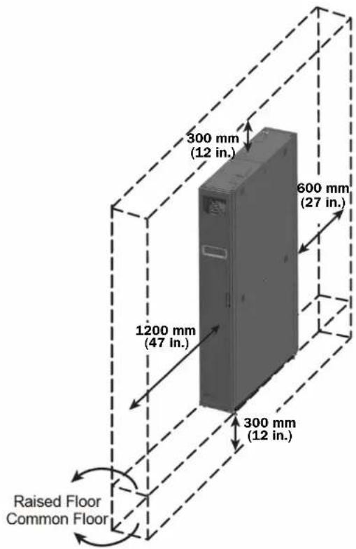
(Figure 3-1: Space reservation)
3. Installation
3.3 Handling
Handling Instructions
Before moving the equipment to the installation site, plan the route according to the following:
1 Make sure the passage, floor, elevator or slope on the handling route can bear the weight of the equipment and handling device, with sufficient net space to avoid collisions.
In the case of a slope on the handling route, its inclination must not be greater than 15 degrees.
The bottom casters are only suitable for short distance movement. For long distance movement, use a handling device (such as a forklift in Figure 3-2) to avoid damage to the casters.
The casters are only suitable for flat surface movement. Avoid moving the unit on uneven ground, which may damage the casters or possibly result in toppling the unit.
5 When moving the unit, pay attention to its height and center of gravity. For optimal safety when moving, at least two people should handle the unit.
Levelers
After the unit is in place, stabilize by rotating the four levelers clockwise with a wrench.
Make sure the unit does not slide or wobble.

WARNING:
The levelers are used only for leveling the unit and cannot be used to compensate for a height difference of the floor.
3.4 Positioning
After moving the unit into place and parallel with the adjacent cabinet, you must ensure the unit's stability. The following two methods can be used, depending on the installation environment:
Cabinet fasteners
Each cooling unit is provided with four connecting fasteners (two at the front and two at the rear). Remove the front and back doors before making the fastener connection. Refer to the following procedures:
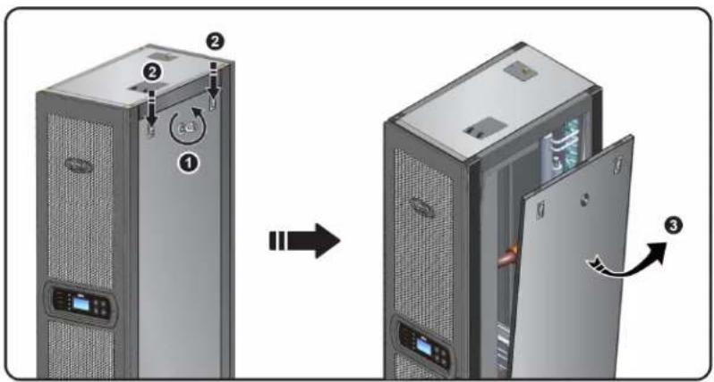
1 If the front door is locked, use the key to open it.
2 Remove the control panel's flat cable and ground wire 1, raise the front door 2 and remove it.

(Figure 3-2: Forklift handling)
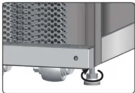
(Figure 3-3: Leveling feet)
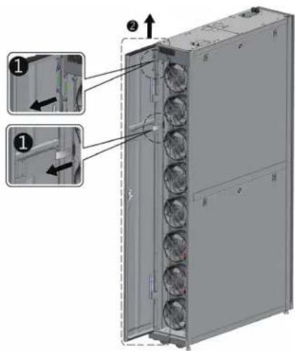
(Figure 3-4: Open the front door)
3. Installation
3 Use a screwdriver to remove the two screws and ground wire from the rear door 1, lean the rear door towards you and lift it up 2 to remove.
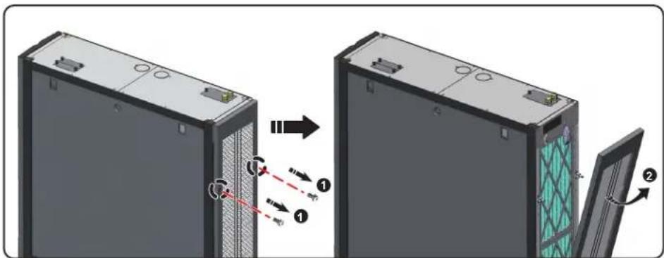
(Figure 3-5: Remove the rear door)
Note: Place the front and rear doors that have been removed in a safe place to avoid any equipment damage or personal injury.
4 Use a screwdriver to loosen the screw below the fastener and lock it on the adjacent cabinet.
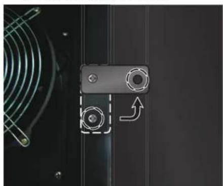
(Cooling unit) (Adjacent cabinet)
(Figure 3-6: Join the cooling unit and the adjacent cabinet together)
5 Secure the front and rear fasteners (8 total) to the adjacent cabinet.
After securing the fasteners, reinstall the front and rear doors.
3. Installation
Hold-down bracket
The hold-down bracket support is used to fix the cooling unit to the pallet during transportation. The bracket can also be used to secure the unit to the ground after positioning.
1 Use two M6 screws to secure the hold down bracket to the frame below the front door (with the extruding part forward) 1.
2 Use expansion screws to secure the extruding end to the floor. ②
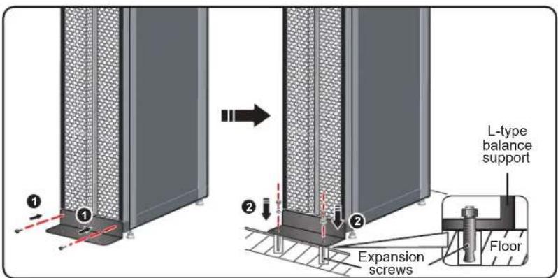
(Figure 3-7: Installation of L-type balance support)
3.5 Side Panel Removal
If side panel is locked, use the attached key to open it. Two latches are located on each of the two side panels. Press the latches downward at the same time and remove the side panel.
(Figure 3-8:Removal of side panel)
To reinstall a side panel, align the two lower holes and press down the latches at the same time.
3. Installation
3.6 Drilling Holes
Drill holes in the raised floor or ceiling according to the piping mode: lower (default) or upper (with SRCOOL60KTP kit, sold separately).
The pipeline is wrapped with an external heat insulation layer to reduce the interference of outside temperature and avoid condensed water. The hole diameter should be approximately 13mm (0.5 in.).
Dimensions: [mm] INCHES
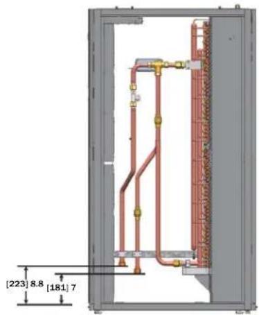
(Figure 3-9: Lower piping positions and dimensions)
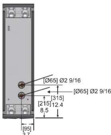
(Bottom view)
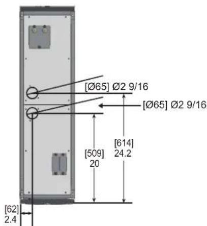
(Top view)
(Figure 3-10 : Hole diameters and positions for lower piping)
Note: To install chilled water supplies from the top of the unit, Tripp Lite offers the SRCOOL60KTP Pipe Installation Kit (sold separately).
3. Installation
3.7 External Piping
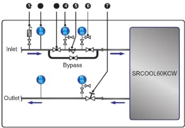
(Figure 3-11: Suggested external piping)
| No. | Description |
| 1 | Automatic exhaust valve |
| 2 | Thermometer |
| 3 | Ball valve |
| 4 | Pressure meter |
| No. Description | |
| 5 | Y-type filter |
| 6 | Shut-off valve |
| 7 | Balance valve |
Configure an external pipeline and an automatic exhaust valve 4 at the water inlet end (as shown in Figure 2-5) for removing the air in the pipeline. Set a Y-type filter 5 in the water inlet pipe to filter out impurities and chemical substances in the water. Install a ball valve 3 in front of or behind the Y-type filter to set up a branch circuit. When the filter needs cleaning or maintenance, close the ball valve to let the chilled water go to the cooling unit via the branch to avoid shut-off loss. Install a pressure meter 4 in front of and after the Y-type filter and determine if there is a blockage according to the pressure difference.
Configure a multi-function balance valve 7 at the return water end for adjusting the return water flow rate.
Pipeline flushing
To guarantee cooling efficiency, you must flush the pipeline to filter out impurities and chemical substances. For pipeline flushing, use a hose to create a short circuit so the chilled water goes directly from the inlet end to the return end without passing through the cooling unit. Use a fine-meshed filter (20-mesh suggested) in the Y-type filter to filter out the fine impurities. After 12 to 24 hours of water circulation in the pipeline, change to a larger-meshed filter (3-mesh suggested).
When using a glycol additive, refer to Appendix 3: Glycol Correction Table for information about cooling capacity and water-side pressure drop.
3. Installation
3.8 Power Connection
Notes:
- The input power must conform to the rated value on the equipment nameplate.
- Input Power Connection by Flexible Cord with Cable Gland: Use a UL-listed flexible cord such as Type-SJT for North America or European equivalent, 2.5 mm²/3C (12 AWG/3C), 300V min., 90°C (194°F) min. with the included cable gland for connection.
- The cooling unit's maximum power consumption is 2400W. Install an appropriate UL-listed breaker (above 300V AC, 20A and 2P is recommended) or European equivalent in front of the input side of the unit to protect other equipment in the circuit if an overload or short occurs.
- In locking the screws for wiring at the power terminal block, use the recommended installation torque of 12.2 kgf·cm (10.6 lbf·in.)
- If there is no wire passing through the communication wire duct at the top of the cabinet, cover the duct with the cover plate provided in the accessory package to avoid dust accumulation.
- The length of the conductor between the cord anchorage and the terminals shall be such that the current-carrying conductors become taut before the earthing conductor if the cord slips out of the cord anchorage.
3.8.1 Power
Single input
1 Pull up the knob 1 and remove the power supply's cover plate 2 at the rear of the cabinet top.

(Figure 3-12: Removal of the power supply's cover plate)
2 Remove the cover plate's knock-out 1, take out the one cable gland from the accessory package, remove the cable gland's nut 2, use the nut to fix the cable gland on the cover plate, and pass the power wires through the cable gland 3.
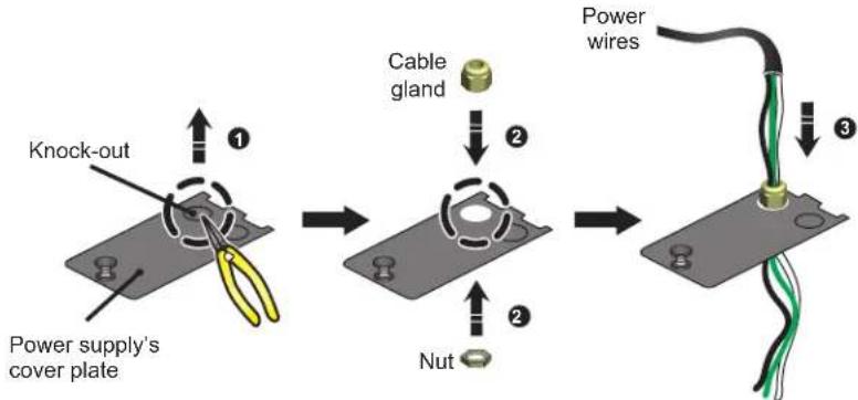
(Figure 3-13: Insertion of power wires)
3. Installation
3 Use a screwdriver to loosen the screws of the wiring terminal block and use ring-type terminals to secure terminal 1, terminal 2 and terminal 5 wires.
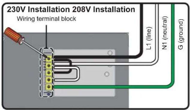
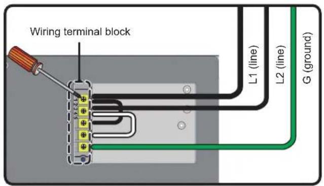
(Figure 3-14: Installation of power wires)
4 Re-install the power supply's cover plate and tighten the cable gland.
(Figure 3-15: Re-install the power supply's cover plate)
Dual input
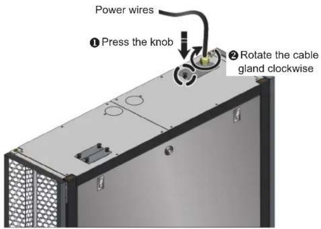
Pull up the knob 1 and remove the power supply's cover plate 2 at the rear of the cabinet top.

(Figure 3-16: Removal of the power supply's cover plate)
3. Installation
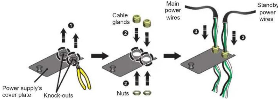
2 Use nippers to remove the cover plate's knock-outs 1, remove the two cable glands from the accessory package, remove the cable glands' nuts 2, use the nuts to fix the cable glands on the cover plate, and pass the power wires through the cable glands 3.
(Figure 3-17: Insertion of power wires)
The SRC0OL6OKCW is factory pre-wired for single input installation. Use a screwdriver to remove the two jumpers connecting number 1 and number 3 terminals, and number 2 and number 4 terminals (see Figure 3-18 below).

(Figure 3-18: Removing pre-installed jumpers)
Use a screwdriver to loosen the wiring terminal block screws and use ring-type terminals to secure the wires into the terminal block.
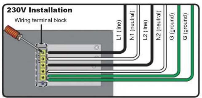

(Figure 3-19: Installation of power wires)
5 Re-install the power supply's cover plate and tighten the cable glands.

(Figure 3-20: Re-install the power supply's cover plate)
3. Installation
3.8.2 Condensed Water Pipe
The condensed water pipe has been connected in the lower part of the cabinet. You must pass the other end through the reserved hole at the bottom to drain the condensed water.
The unit's condensed water pump supports lower (default) and upper piping configuration (with optional SRCOOL60KTP kit, sold separately). If the upper piping is selected, the height of the condensed water pipe should not be higher than 5 m (16 ft.).
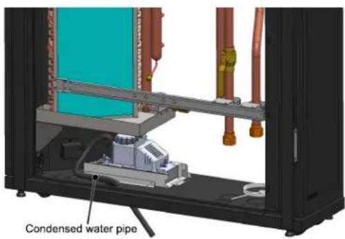
(Figure 3-21: Installation of the condensed water pipe)
3.8.3 Control Box
Front
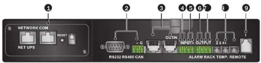
(Figure 3-22: Front of control box)
| No. | Item | Description |
| 1 | Network Interface | This unit contains a preinstalled network interface that can be connected to a network to manage the system based on the SNMP protocol. To use, connect an RJ45 cable (sold separately) from the interface to the workstation. See 6. Network Configuration for operation and settings. |
| 2 | RS-232 and RS-485 Ports | The RS-232 or RS-485 port connects a workstation based on Modbus protocol for remote use. |
| 3 | CAN-Link IN/OUT | Reserved for series connection of several cooling units, it adopts one-Input one-Output mode. |
| 4/5 | Input Dry Contacts | Used for connecting the fire alarm or smoke detector. When an event occurs, the dry contact device is triggered to form a short circuit. The system will record it in the event log, start the buzzer and light the FAULT indicator. Port4: Fire alarm Port5: Smoke detector |
| 6/7 | Output Dry Contacts | Connect two dry contact output devices and trigger the contacts at specific events. Port6 (System alarm event): Normally open. Connect the dry contact device to this port and the device will be triggered when an alarm event occurs (close the circuit). You may set the triggering conditions. Refer to 5.7.2 Local setting. Port7 (Cooling unit startup) Normally open. Automatically trigger to form a short circuit at the start of the cooling unit to remind the chiller to output chilled water and turn to the normally open status until the cooling unit is powered off. |
| 8 | Remote Temperature Sensor Ports | At most, three remote temperature sensors (two are provided) can be connected. It is suggested that qualified service personnel connect and locate the remote sensors during installation to ensure accurate detection of heat load temperature. Note: Do not relocate the remote temperature sensors unless authorized. |
| 9 | Remote Temperature and Humidity Sensor Port | Connects the SRC00L6OKRTH (remote temperature-humidity sensor, sold separately) or SRC00L6OKRT (remote temperature sensor, sold separately) for accurate detection of the temperature and humidity of heat loads. It is suggested that qualified service personnel perform installation. |
4. Initial Startup
4.1 Pre-Startup Inspection

WARNING:
- Only qualified service personnel should carry out the installation procedures in this section.
- The high voltage of this unit is potentially fatal! Make sure the input power has been disconnected before performing the following actions.
- A startup without correctly completing this section may lead to serious personal injury or equipment damage!
Complete all the following inspections before the initial startup procedures.
Inspection List
General items
The unit has no external damage.
The unit is stable.
All the installation procedures have been performed in accordance with the instructions in 3. Installation.
The pipes inside and outside the cabinet have been correctly connected and the thermal insulating layer of the pipes are free of damage and leakage.
The front and back doors have been reinstalled and the control panel's flat cable has been connected.
Environment
The operating environment is an enclosed space and isolated from interference from outside temperature and humidity.
The reserved space around the cabinet conforms to the minimum space requirements (see 3.2 Placement).
Electrical connection
The rated value of the input power conforms to that marked on the nameplate.
The equipment has been properly grounded.
All electrical connections are tight and secure.
The remote temperature (humidity) sensors have been correctly connected and located properly.
The water leakage detector has been correctly laid out.
Mechanical connection
The pipes and valves are free of leaks or visible damage.
The condensed water drain pipe has been correctly connected and led to the drain.
The temperature of the water supplied by the external chiller is stable (5 15^ / 41 59^)
4.2 Power Supply
Power on the cooling unit and it will automatically enter standby mode. As a safety precaution, the fans will not automatically rotate. Only when the unit enters manual mode, automatic mode, force mode or installation mode and returns to the standby mode, will the fans run at the minimum speed. After the Tripp Lite logo displays for six seconds, the LCD will show the following status screen:

Figure 4-1: LCD status screen)
For a description and operation of each screen, refer to 5.2 Control Panel Operation.
4. Initial Startup
4.3 Coolant Line Purge
You must carry out the following air purge procedures to purge the air in the pipe:
1 Open the shutoff valve and the bypass valve.
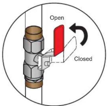
(Figure 4-2: Completely open the shutoff valve and the bypass valve)
2 Rotate the outlet water pipe's manual exhaust valve counterclockwise.
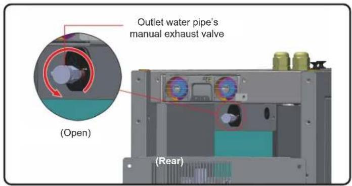
(Figure 4-3: Open the outlet water pipe's manual exhaust valve—illustration shown with top cover removed)
3 Open the water inlet's user-supplied valve to let the water slowly flow into the pipe. After the water flows into the pipe, the air will be squeezed out.
After 6-7 seconds, when the air is exhausted and the water begins to discharge from the pipe, close the valve in the reverse method in which it was opened.
Note: Do not perform the air exhaust procedures after making any changes in the pipeline structure. It is recommended to install an automatic exhaust valve for external piping. Refer to 3.7 External Piping.
4. Initial Startup
4.4 Operating Temperature and Humidity
Use an auxiliary dehumidifier or air conditioner to adjust the indoor temperature and humidity until they fall within the acceptable operating range.

WARNING:
If the indoor humidity is too high, the condensing effect around the coil may lead to too much condensed water, which could cause leakage or trigger an alarm.
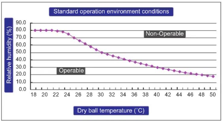
(Figure 4-4: Standard Operation Conditions)
If there is no auxiliary dehumidifier or air conditioner indoors, you may start the installation mode to reduce the humidity in the cabinet. Use the following procedure:
1 In the status screen, press enter into Main Menu, use and to select Factory Setting, then press
Enter administrator password (see 5.4 Account Authority and Login).
After entering the password, select the installation mode and press to confirm. The fans will now run at the minimum speed, the three-way ball valve will fully open and the bypass will close. Press ESC repeatedly to return to the status screen and monitor changes in temperature and humidity.
When the humidity falls within the acceptable operating range, the WARNING indicator will flash and the buzzer will issue sustained short beeps for 0.5 second. The alarm will continue until you leave the installation mode.
4. Initial Startup
4.5 Water Leakage Detector
This cooling unit contains a connection for the SRC00L60KDR water leakage detector (sold separately) at the bottom of the cabinet. When installed, the water leakage detector will be triggered to issue an alarm when in contact with water or liquid, alerting you to take proper measures. You must manually set the detector for leakage detection on-site and in a low-lying place. If the lower piping configuration is adopted, it is suggested to set it close to the pipeline below the raised floor.
Pass one end of the water leakage detector through the small hole at the lower part of the cabinet and set the detector at the above-mentioned place.
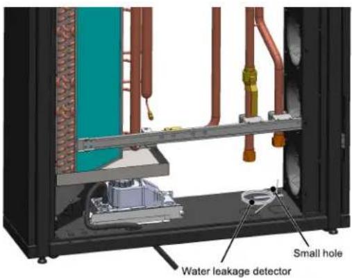
(Figure 4-5: Water leakage detector installation)
4.6 Water Balance
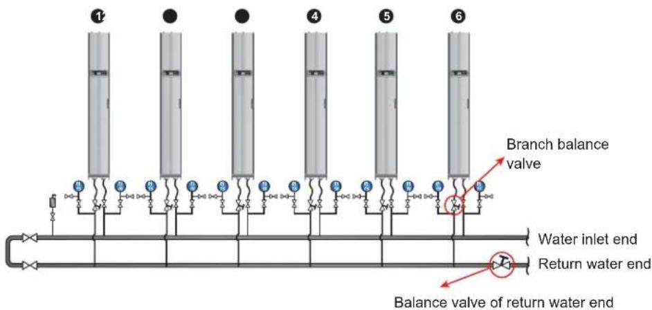
(Figure 4-6: Water balance)
The program adopts a compensation method and adjusts the flow rate with the first (most remote) cooling unit as a reference point. The process involves at least three assistants. Maintaining communication via handheld communication devices is suggested. The number of cooling units in a circuit varies. For the following steps, a six-unit configuration is used as an example.
1 Set a balance valve at the return water end of the main pipe to adjust the total flow rate of the circuit.
Use the control panel to set all cooling units in installation mode (see 4.4 Operating Temperature and Humidity). The three-way ball valves will automatically open completely (100%).
3 Fully open the balance valve of the return water end and the branch balance valves at all branches. Record the flow rate of each unit.
4 Adjust the balance valve of the return water end to 110% of the rated total flow rate. If the balance valve cannot reach this value when fully opened, keep it at full opening and adjust the flow rate of each branch proportionally.
5 Fully open the branch balance valve of Unit 1. Then adjust the balance valve of the return water end of the main pipe circuit to enable Unit 1 to reach its rated flow rate (± 5%) . Make sure once again its branch balance valve is kept fully open.
4. Initial Startup
Adjust the branch balance valve of Unit 2 for it to reach the rated flow rate. Another person will observe the flow rate change of Unit 1, dynamically adjust the balance valve of the return water end and compensate water to enable Unit 1 to reach the rated flow rate (± 5%) . After adjustment, record the opening of the branch balance valve of Unit 2.
7 Adjust the branch balance valve of Unit 3 for it to reach the rated flow rate. Another person will observe the flow rate change of Unit 1, dynamically adjust the branch balance valve of Unit 1 and compensate water to enable Unit 1 to reach the rated flow rate (± 5%) . After adjustment, record the opening of the branch balance valve of Unit 3.
Repeat steps 6 7 to adjust Units 4 6 and record the opening of the branch balance valves.
9 When all units are adjusted, record the opening of the balance valve of the return water end and the total flow rate (rated flow rate ± 10%
10 If the circuit is unable to reach the rated value of the total flow rate after adjustment, adjust the water flow of the chiller and water pump.
4.7 PID Setting
Due to differing data center environmental conditions, the PID parameter values must be adjusted by qualified service personnel after installation to achieve the best cooling efficiency.
Note: First read 5.2 Control Panel Operation to get familiar with basic operation.
Path: Main Menu Setting Controller

(Figure 4-7: PID Setting Values)
Proportional constant (P)
Adjust between the measured temperature and the set value.
Integration constant (I)
Add or subtract the integration coefficient by small incremental output.
Differential constant (D)
Adjust the output to correct the time-dependent correction rate.
The PID default values of the three-way ball valve are:
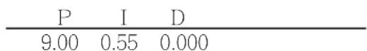
Adjustment procedures
The adjustment is made based on an open circuit method as follows:
1 Keep the fans running at high speed (at least 70% ) and observe the flow rates at the high, medium, and low openings of the three-way ball valve from the control panel.
2 Adjust the three-way ball valve to the opening at half of the rated flow rate, which varies according to the pipeline configuration and pressure distribution at site. If the opening is too large (above 70% ), reduce it to a medium opening (about 50% ).
3 When the temperature and humidity of outlet air and return air are stable, record the readings of time-dependent outlet air temperature and observe if the inlet and outlet water temperatures are stable.
Use the control panel to start the manual mode and increase the opening (above 75% ). Due to the internal delay of the system, the outlet air temperature will change over time.
4. Initial Startup
5 Execute the Modbus Recorder* program via the RS485 interface and calculate Td and t values. The definition is as follows: T = 1.5 × (T2 - T1) [the time difference between 28.3% (T1) and 63.2% (T2) x 1.5]
Td (Pseudo Dead Time) may be defined as Td = T1 - T
- Various OS versions of this tool can be found at http://www.modbustools.com/modbus POLL.html
6 Calculate the best PID values in different modes in accordance with the below table:
| Mode Gain Reset | ** Derivative** | ||
| P tau/ (Td x G*) | |||
| PI 0.9 tau/ (Td x G*) 0.3/ Td | |||
| PID 1.2 tau/ (Td x G*) 0.5/ Td 0.5 Td |
- G (response gain): it varies with opening values and therefore, the medium opening or the opening at a medium flow rate is selected as the reference point.
** Reset and Derivative are defined: Reset = I/P, Derivative = D/P
The I and D values can be found from the Reset and Derivative values.
8 Enter the PID values found on the control panel, start the automatic mode and observe any temperature oscillations. If the temperature is stable, record the value on a sheet of paper and input the adjusted set values (including supply air and return air temperature and humidity, fan speed, inlet water temperature, and outlet water temperature) via the SNMP interface.
Operation trial
- Confirm that the cooling unit is in automatic mode and observe if the supply and return air temperature and humidity, water flow rate and water temperature are stable.
- Change the set point, record the stability time (reaching the set point of supply air temperature) via the SNMP interface, and observe if there is instability and temperature oscillation.
- Export and store the data.
5. Operation
5.1 LCD Hierarchy
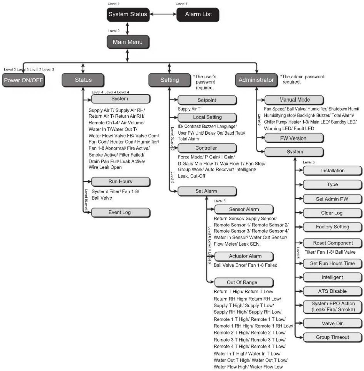
(Figure 5-1: LCD hierarchy)
5. Operation
5.2 Control Panel Operation

No. Button Description
| 1 ESC | Returns to previous screen or cancels current operation. | |
| 2 | ← ↓ | Enters your selected item or confirms your selection or setting. |
| 3 | ▲ | Goes back to previous screen, moves up or increases number. |
| 4 | ▼ | Goes to next screen, moves down or decreases number. |
After entering a screen, if its options exceed four, you may press to advance the page. Press a highlighted zone to appear within the current selected page. Press to move the highlighted zone.
To enter or change values (such as password or temperature), use . Press skip to next field. In the last field, press to store and submit. Press ESC to cancel the current operation.
If the unit becomes idle, the LCD and backlight will automatically turn off.
Note: The default language of the control panel is English. The path for setting your preferred language is Main Menu → Setting → Local Setting → Language.
5.3 Status Screen and Main Menu

The LCD and backlight will turn off when the unit is idle. Press to wake up the backlight and display the status screen. On the status screen, the air supply status and the air flow percentage of the fans is shown. The air flow percentage represents the fan speed and the more solid status bars shown indicate higher fan speed.
In the status screen, press Enter the Main Menu shown below.
If an alarm occurs, press and you will see a screen display the description of the alarm.

Power ON/OFF
Start up the cooling unit (automatic mode) or enter standby mode.
Status
View the system, run hours and event log.
Setting (User's password required)
Adjust the set point, local setting, controller setting and alarm setting.
Administrator (Admin password required)
Enter the manual mode to view the firmware version and system setting.
5. Operation
5.4 Account Authority and Login
The cooling unit has two accounts. The administrator account has the highest authority and can alter all settings. The user account can only alter the system setting.
Input Password 0000
When you try to enter the Setting or Administrator screen, a password prompt will appear. If no operation is performed after login, the login status will become invalid after the system becomes idle. If you want to re-enter the above menu, you must re-enter the password.
In the password prompt screen, entering the admin password permits administrator use and entering the user password represents the permission of general users. If you only enter the Power ON/OFF or Status screen, no password is required.
The user's default password is 0000.
Note: To avoid unauthorized access and changes to important settings, do not disclose the admin password. To obtain the admin password, contact your service personnel.
5.5 Operation Modes
The cooling unit has five operation modes:
| Operation mode Description | |
| Automatic mode | Path: Main Menu → Power ON/OFF → ONTo get the cooling unit to automatically control its cooling capacity, select the automatic mode and the system will automatically micro-adjust the fan speed and the opening of the three-way ball valve in accordance with the set points.You may also simultaneously press ▲▼ for three seconds in any screen to quickly switch between the automatic mode and the standby mode.Note: In the manual mode, simultaneously pressing ▲▼ for 3 seconds will NOT make the unit automatically enter automatic mode or standby mode. |
| Standby mode | Path: Main Menu → Power ON/ OFF → StandbyIn standby mode, the fans run at the minimum speed, the three-way ball valve is fully closed and the chilled water goes through bypass without passing the coil. |
| Manual mode | Path: Main Menu → Administrator → Manual ModeThe manual mode is used to test if the components work normally or to make the system operate in accordance with the manual setting. In this mode, you may manually set: fan speed, ball valve opening, indicator on-off, backlight on/off, buzzer on/off, alarm dry contact on/off and chiller's water pump dry contact on/off.In the manual mode, press ESC to automatically return to the standby mode. |
| Installation mode | Path: Main Menu → Administrator → System → InstallationThis mode is used to dehumidify and adjust the water balance. When it is started, the three-way ball valve will fully open and the fans will rotate at the minimum speed. When the system humidity falls within the acceptable operation range, the WARNING indicator will flash and the buzzer will issue 0.5 second beeps continuously until you leave the installation mode.For more information on the operating temperature and humidity, refer to 4.4 Operating Temperature and Humidity. |
| Force mode | Path: Main Menu → Setting → ControllerThe three-way ball valve is fully open and the fans run at the highest speed. This mode is generally used for unit testing or emergency cooling requests. |
5. Operation
5.6 Shutdown
Path: Main Menu Power ON/ OFF Standby


WARNING:
In standby mode, the unit is still in power-on status! You must disconnect the input power to fully power the unit off in standby mode.
To shut down the cooling unit, first enable standby mode. After selecting standby mode, select Y, then press to confirm. If the STANDBY indicator displays, the unit is in the standby mode. The cooling unit is still in power-on status and the fans will be running at the minimum speed.
Next, disconnect the external power supply. Check to make sure the fans stop and the LCD is off.
5.7 Cooling Unit Settings
5.7.1 Set Point
Path: Main Menu Setting Set point

Supply Air T (temperature)
In automatic mode, the cooling unit will automatically adjust the fans and three-way ball valve in accordance with the set supply air temperature.
5.7.2 Local Setting
Path: Main Menu Setting Local Setting


System time
Use ▲▼ to set up the system time, press ←skip to the next field. Then press to confirm.
IB (Number)
Represents the number of the cooling unit connected in series and also the ID in the Modbus protocol. The default number is 1. If several cooling units are connected in series, you must designate each unit with a different number.
5. Operation
Contrast
Adjusts the display screen contrast (0~5). The default value is 2.
Buzzer
Sets the buzzer on/off and issues an audible alarm to remind the user of any alarm events. The default is ON.
Language
Set the display language. Select a language and press confirm. The default is English (EN).
User PW
To change the current user's password, enter four digits.
Unit
Sets the temperature unit. The default is (^)
Delay On
Shows the time difference between setting the startup in automatic mode and the unit's actual operation. The cooling unit will start up in the seconds you have designated.
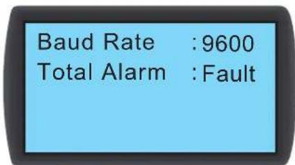
Baud Rate
Sets the on-line speed based on the Modbus protocol. Options include 9600, 19200, 38400 and 57600. The default value is 9600.
Total Alarm
Decides what event can trigger the output dry contact 1. Refer to the following:
- All: Any alarm and fault event can trigger it.
- Fault: Only fault events can trigger it.
Alarm events
- Filters are clogged 5. High and low chilled water flow
- Abnormal internal communication 6. High and low remote temperature and humidity
- High and low air supply/return temperature and humidity 7. Maintenance overtime
- High and low chilled water inlet/outlet temperature
Fault events
- Emergency stop/remote emergency stop 7. Abnormal remote sensor
- Condensed water overflow 8. Abnormal chilled water inlet/outlet temperature sensor
- Leakage alarm/leakage open-circuit alarm 9. Abnormal chilled water flow meter
- Fire 10.Abnormal fan
5.Smoke 11.Abnormal three-way ball valve - Abnormal air supply/return temperature and humidity sensor
5. Operation
5.7.3 Controller Setting
Path: Main Menu Setting Controller


Force Mode
When force mode is enabled, the fans will run at full speed and the three-way ball valve will fully open. Force mode is generally used for performance testing or a high heat load.
If the STANDBY indicator on the control panel flashes, the unit is in force mode. Set the proportional constant, integral constant and derivative constant (PID). Refer to 4.7 PID Setting.
Min Flow T
When the return air temperature is lower than this value, the fans will run at the minimum speed to save energy. The default is 25^ (77°F).
Max Flow T
When the return air temperature is higher than this value, the fans will run at the maximum speed. The default is 40^ (104°F).
F#n Step
Sets the fan speed (range: 0~15) in automatic mode. The default is 0 and the cooling unit will adjust the fan speed according to your setup.
Auto Recover
When this function is enabled and the system is in automatic mode before powering off, the unit will directly return to the automatic mode at restart.
Intelligent
Will display if the intelligent temperature control is enabled. This option only displays the status; you cannot change the setting. To change settings, refer to 5.7.10 Setting Automatic Control Mode.
Leak Cut-Off
If this function is enabled, the unit will automatically shut down when water leakage is detected.
5.7.4 Alarm Setting
Path: Main Menu Setting Set Alarm

Sets Sensor Alarm, Actuator Alarm and Out-of-Range Alarm. If an item display is , this item is disabled. Press at this item, use to select , and press confirm the item is enabled.
Note: When an alarm event occurs in manual mode, the indicator and buzzer will not activate, though the event will be stored in the event log.
5. Operation
Sensor Alarm
Path: Main Menu Setting Set Alarm Sensor Alarm
Return Sensor :
Supply Sensor
Remote Sensor 1:
Remote Sensor 2:□
Remote Sensor 3:□
Remote Sensor 4:□
Water In Sensor :☑
Water Out Sensor:
Flow Meter
Leak SEN. :High
Enables/disables the alarm for Return Sensor, Supply Sensor, Remote Sensor 1-4, Water In/ Out Sensor, Flow Meter and Leak SEN (leakage detector sensitivity).
Actuator Alarm
Path: Main Menu Setting Set Alarm Actuator
Ball Valve Error :☑
Fan 1 Abnormal :☑
Fan 2 Abnormal :☑
Fan 3 Abnormal :☑
Fan 4 Abnormal :☑
Fan 5 Abnormal :☑
Fan 6 Abnormal :☑
Fan 7 Abnormal :☑
Fan 8 Abnormal
Enables/disables the alarm for ball valve and fan 1~8.
Out-of-Range Alarm
Path: Main Menu Setting Set Alarm Out Of Range
□ Return Air T High: - - - - - - - - - - - - - - - - - - - - - - - - - - - - - - - - - - - - - - - - - - - - - - - - - - -
□ Return Air T Low: - - - - - - C
Return Air RH High:----%
Return Air RH Low: ----%
5.7.5 View System Status
Path: Main Menu Status System
12/04/30 10:10:00
Capacity :25.2KW
Supply Air T :25°C
Supply Air RH:50%
Return Air T :35°C
Return Air RH :35%
Remote Ch1 T :----°C
Remote Ch1 RH:----%
Remote Ch2 T:----°C
Remote Ch3 T:----°C
Remote Ch4 T:----°C
Air Volume :----CMM
Inquires about system-related information, including cooling capacity, supply air temperature and humidity, return air temperature and humidity, remote 1 temperature and humidity, remote 2 temperature, remote 3 temperature, remote 4 temperature, chilled water inlet/outlet temperature, chilled water flow rate, ball valve opening, ball valve command (set the ball-valve opening), fan command (set the fan speed), heater command, humidifier command, fan 1~8 failed, E.P.O. active, fire active, smoke active, filter failed, drain pan full, leak active (enable the leakage detection) and wire leak open (water leakage detector has open/short issues).
5. Operation
5.7.6 View / Reset Running Hours
Path: Main Menu Status Run Hours

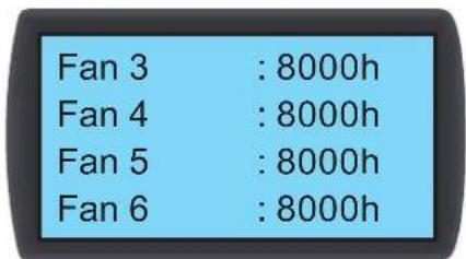
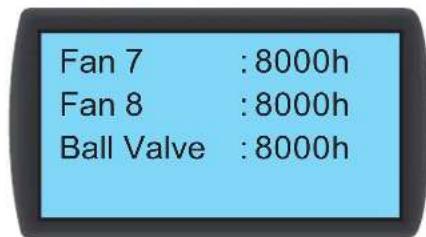
Inquires about the system and unit components for assistance in evaluating the component status and determining a repair or replacement time.
5.7.7 View / Clear Event Log
Path: Main Menu Status Event Log

In this screen, the number of current events/total events is displayed. A maximum of 3,000 events can be recorded. Press to switch events. The events are numbered according to the occurrence time. The older the event, the smaller its number is. The digit in << is the event code. If the records exceed 3,000, older events will be overwritten.
An admin password is needed to clear any event log. The path is: Main Menu Administrator System Clear Log.
Note: The event log is important information for evaluating the system status and also a reference for service personnel to perform maintenance. Therefore, do not clear the event log without authorization.
5.7.8 Change of System Type
Path: Main Menu Administrator System Type

Follows your data center's cold/hot aisle configurations to set up the system type: OPEN or CLOSED.
5. Operation
5.7.9 Restoring Default Settings
Path: Main Menu Administrator System Factory Setting
Factory Setti
Reset Component
Set Run Hours Time
1100h
Restores all factory defaults, including the set options and user and admin passwords.
The path for resetting a component's operation time is: Main Menu Administrator System Reset Component.
After a component is changed, reset the operation time of Filter, Fan 1-8 and Ball Valve.
System
Filter
Fan 1
Fan 2
Sure?

WARNING:
The restoration of factory defaults will reset the settings or parameters that have been changed! The cooling unit has selected different settings according to the different environment. Random restoration may lead to system error. System restorations should only be made by qualified service personnel.
5.7.10 Setting Automatic Control Mode
Path: Main Menu Administrator System Intelligent
Intelligent : OFF
This unit supports two kinds of automatic control modes:
1. Intelligent control (default)
The system will automatically adjust the fans and the actuator in accordance with the set supply air temperature.
2. PID control
The system will make adjustment by PID parameters.
When the unit enters automatic mode, the default setting is intelligent control. If the intelligent control mode is off, the system will automatically adopt the PID control. The admin password is required to turn the intelligent control on/off.
6. Network Configuration
6.1 SNMP Configuration
There are multiple ways to configure the unit:
- Web-based Interface: The interface offers comprehensive system management and monitoring. Refer to 6.1.1 Configuring via Web-Based Interface for more information.
- TLNET (System) Configurator: Use the downloadable TLNET Configurator utility to quickly set up the network interface over the network. Refer to 6.1.2 Configuring with TLNET (System) Configurator for more information.
- Telnet Mode: Configure the network interface over the network in text mode. Refer to 6.1.3 Configuring via Telnet for more information.
COM Port: If a network connection is not available, the network interface can be configured through its COM port. Refer to 6.1.4 Configuring through COM Port for more information.
Notes:
- When initially connected to the network, the unit will attempt to obtain an IP address via DHCP. If DHCP is disabled on the network, the unit can be accessed using its default IP address: 192.168.1.100.
To ensure system security, it is highly recommended the account and password be changed after the first login.
6. Network Configuration
6.1.1 Configuring via Web-Based Interface
To set up the system via your web browser, follow the instructions below:
Step 1: Use a Cat5 network cable to connect the interface's network port to the network. Launch your web browser and enter the default IP address 192.168.1.100 in the address bar.
Step 2: Log in as Administrator (default username/password: admin/password, case sensitive).
Step 3: Click System Administration User Manager to set up accounts and passwords under the "Local Authentication" section. The access permissions for the account types are as follows:
1) Administrator: Allowed to modify all settings.
2) Device Manager: Allowed to modify device-related settings.
3) Read Only User: Allowed to view settings only.
Manually specify whether users are allowed to log in from other LANs. If login attempts from external connections are to be blocked, select Only in This LAN. Otherwise, select Allow Any.
Step 4: Click System Administration TCP/IP to set Host Name, IP address, Subnet Mask and Gateway IP for the interface.
Step 5: Click Time Server to manually set time and date for the system, or enable automatic time synchronization between the interface and the time servers.
Note: To completely set up the network interface, refer to 7. Precision Cooling Dashboard Software.
6. Network Configuration
6.1.2 Configuring with TLNET (System) Configurator
The downloadable TLNET Configurator utility (compatible with Windows 2000/2003/2008/XP/Vista/7) enables easy configuration and firmware upgrade of the system's SNMP configuration. Follow the instructions below:
Step 1: Use a Cat5 cable to connect the network port to the network.
Step 2: Ensure the two DIP switches are set to the OFF position (Normal Mode) to enable network communication and that the workstation and the SRCOOL60KCW are on the same LAN.
Step 3: Once downloaded, launch the Configurator.
Step 4: Click Discover to search all available SNMP devices on the LAN. A list of devices will be shown.
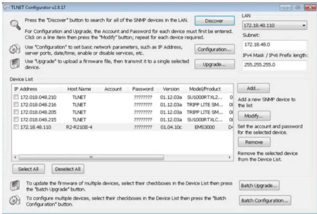
Notes:
To search for SNMP devices in a different domain, change the Subnet and IPv4/IPv6 Prefix Length and click Discover.
- If the unit cannot be found, verify that UDP port 3456 on the workstation is open.
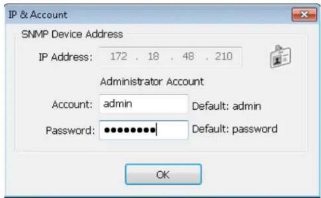
Step 5: Select the SRC00L60KCW to be modified from the Device List. Click Modify and enter the Administrator's account and password (default: admin/password, case sensitive).
6. Network Configuration
Step 6: Click Configuration to modify network settings.

6.1.3 Configuring via Telnet
Step 1: Use a Cat5 network cable to connect the network port to the network.
Step 2: Connect the workstation (Windows or Linux) to the LAN that the SRCOOL60KCW is connected to.
Step 3: For Windows, launch DOS prompt mode (Start Run key in cmd and press Enter). For Linux, launch Shell.
Step 4: Enter telnet <<IP Address>> to initiate telnet connection with the unit.
Step 5: When connection is established, enter an Administrator's account and password (default: admin/password, case sensitive). The Main Menu will appear on the screen. Refer to 6.1.5 Configuring via Text Mode for more information.
Notes:
The unit will terminate any idle connections after 60 seconds.
For complete configuration, refer to 7. Precision Cooling Dashboard Software.
6. Network Configuration
6.1.4 Configuring through COM Port
If a network connection is not available, the system can be configured via COM port connection. Follow the instructions below:
Note: If running a non-Windows system, refer to your system's user manual for Telnet clients.
Step 1: Use the provided RJ45 to DB9 cable to connect the SRC00L60KCW's COM port to the workstations' COM port.
Step 2: Ensure the two DIP switches are set to the OFF position (Normal Mode).
Step 3: For Windows 2000, 2003, 2008 and XP, go to Start Programs Accessories Communications and select HyperTerminal.
Note: Microsoft® has removed HyperTerminal from Windows Vista and later versions. If the OS does not include the program, a free alternative Telnet/ SSH client PuTTY can be downloaded from http://www.putty.org.
Step 4: Enter a name, choose an icon for the connection and click OK. From the Connect drop-down menu, select the COM port that is connected to the SRCOOL60KCW.
Step 5: Click Configure and set up COM port parameters as follows:
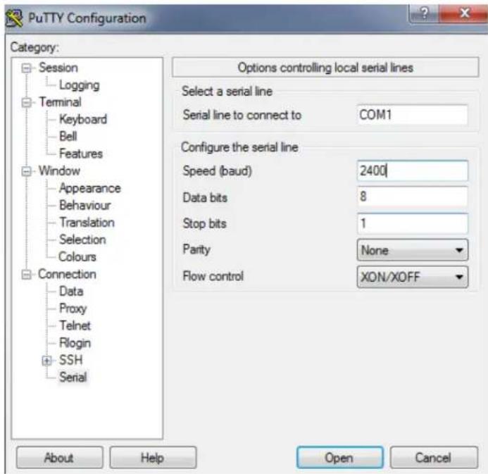
Step 6: Click OK to continue. Set the two DIP switches to the ON position (Configuration Mode). HyperTerminal will automatically connect to the system; if it doesn't, click the telephone icon in the tool bar. When a connection is established, log in with an Administrator's account/password (default: admin/password, case sensitive). Once logged in, the Main Menu appears on the screen. Refer to the next section for more information.
6. Network Configuration
6.1.5 Configuring via Text Mode
This section contains descriptions and default settings for configuration using a Telnet/SSH client such as HyperTerminal or PuTTY.
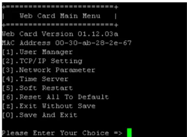
Main Menu
User Manager

| No. | Item Description Default | ||
| [1] | RADIUS Auth Specifies whether RADIUS is allowed. | Disable | |
| [2] | Server The RADIUS server's name. | ||
| [3] | Secret The RADIUS secret. | ||
| [4] | Port The RADIUS port number. 1812 | ||
| [5] | Administrator Account | The Administrator's default account/passport (case sensitive). | admin |
| [6] | Administrator Password | password | |
| [7] | Administrator Limitation | Restricts Administrator login area. Only in This LAN | |
| [8] | Device Manager Account | The Device Manager's default account/passport (case sensitive). This account is only permitted to change device-related settings. | device |
| [9] | Device Manager Password | password | |
| [a] | Device Manager Limitation | Restricts Device Manager login area. | Only in This LAN |
| [b] | Read Only User Account | The Read-Only User's default account/passport (case sensitive). This account is only allowed to view settings. | user |
| [c] | Read Only User Password | password | |
| [d] | Read Only User Limitation | Restricts Read-Only User login area. | Allow Any |
6. Network Configuration
TCP/IP Setting
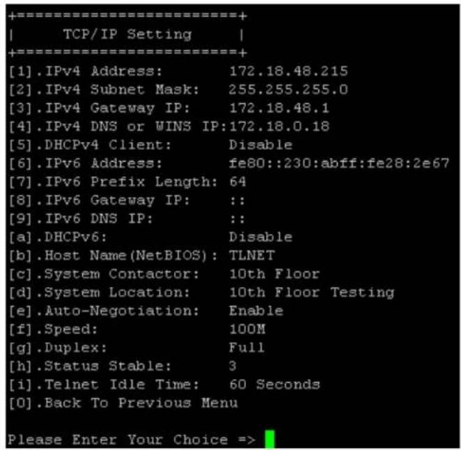
| No. | Item | Description | Default |
| [1] | IPv4 Address | The IPv4 address. | 192.168.001.100 |
| [2] | IPv4 Subnet Mask | The IPv4 subnet mask setting. | 255.255.255.000 |
| [3] | IPv4 Gateway IP | The IPv4 gateway's IP address. | 192.168.001.254 |
| [4] | IPv4 DNS or WINS IP | IPv4 Domain Name Server or WINS IP | 192.168.001.001 |
| [5] | DHCPv4 Client | Enable/Disable DHCPv4 protocol. | Enable |
| [6] | IPv6 Address | The IPv6 address. | |
| [7] | IPv6 Prefix Length | The IPv6 prefix length. | |
| [8] | IPv6 Gateway IP | The IPv6 gateway's IP address. | |
| [9] | IPv6 DNS IP | IPv6 Domain Name Server's IP address. | |
| [a] | DHCPv6 | Enable/ Disable DHCPv6 protocol. | Enable |
| [b] | Host Name (NetBIOS) | The Host Name for the network interface. | TLNET |
| [c] | System Contactor | The System Contact information. | |
| [d] | System Location | The System Location information. | |
| [e] | Auto-Negotiation | Enable/disable automatic transfer rate (10/100Mbps) negotiation. | Enable |
| [f] | Speed | If the Auto-Negotiation is disabled, you can specify the transfer rate. | 100M |
| [g] | Duplex | If the Auto-Negotiation is disabled, you can specify the duplex mode. | Full |
| [h] | Status Stable | Status change confirmation check time. | 3 |
| [i] | Telnet Idle Time | Telnet connection time-out setting. | 60 Seconds |
Network Parameter
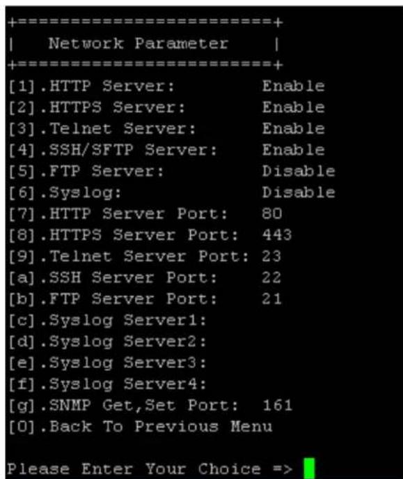
| No. | Item Description Default | |
| [1] | FTP Server Enable/disable HTTP protocol. Enable | |
| [2] | HTTPS Server Enable/disable HTTPS protocol. Enable | |
| [3] | Telnet Server Enable/disable Telnet protocol. Enable | |
| [4] | SSH/SFTP Server Enable/disable SSH/ SFTP protocol. Enable | |
| [5] | FTP Server Enable/disable FTP protocol. Disable | |
| [6] | Syslog Enable/disable remote Syslog. Disable | |
| [7] | FTP Server Port HTTP port. 80 | |
| [8] | HTTPS Server Port HTTPS port. 443 | |
| [9] | Telnet Server Port Telnet port. 23 | |
| [a] | SSH Server Port SSH port. | 22 |
| [b] | FTP Server Port FTP port. | 21 |
| [c] | Syslog Server 1 The Host Name of remote Syslog Server 1. | |
| [d] | Syslog Server 2 The Host Name of remote Syslog Server 2. | |
| [e] | Syslog Server 3 The Host Name of remote Syslog Server 3. | |
| [f] | Syslog Server 4 The Host Name of remote Syslog Server 4. | |
| [g] | SNMP Get, Set Port The SNMP port. | 161 |
6. Network Configuration
Time Server
You can manually adjust time and date or set up automatic time server synchronization. The SRC0OL60KCW, Windows XP and later versions support SNTP (Simple Network Time Protocol).
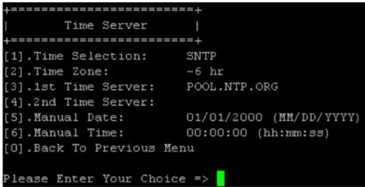
| No. | Item Description | Default | |
| [1] | Time Selection SNTP | or manual. SNTP | |
| [2] | Time Zone Adjust you | ur time zone. +0 hr | |
| [3] | 1st Time Server The | first time server for SNTP. | POOL.NTP.ORG |
| [4] | 2nd Time Server The | second time server for SNTP. | — |
| [5] | Manual Date Set the | date manually. 01/01/2000 | |
| [6] | Manual Time Set the | time manually. 00:00:00 |
Soft Restart
Reset the interface. This will not affect the operation of the cooling unit.
Default Reset
Reset to factory defaults.
Exit Without Saving
Exit and ignore changes.
Save and Exit
Preserve your changes and exit.
7. Precision Cooling Dashboard Software
To configure the system via the Precision Cooling Dashboard, follow the steps below:
Step 1: Ensure the SRCOOL60KCW is connected to the LAN.
Step 2: The login page will appear when a connection is established. Enter the user name (default: admin) and password (default: password).

Tripp Lite Precision Cooling Dashboard Login
Copyright © 2015 Tripp Life, Inc. All Rights Reserved.
Notes:
If unable to log in with the correct user name and password, additional network configuration may be needed. The IP subnet of the computer may be different from the SRCOOL6OKCW.
The SRCOOL6OKCW will automatically log off if the connection is idle for 30 minutes.
The Precision Cooling Dashboard contains three main sections: Monitor, Device and System. Refer to Sections 7.1 and 7.2 for more information.
7.1 Monitor
7.1.1 Status and Information
From the Monitor page, you can find the cooling unit's status and information. The information will be updated every 10 seconds or you can press F5 to refresh immediately.

Signal Color Meaning
Gray No function.
Green Normal operation.
Red Alarm or warning.
7. Precision Cooling Dashboard Software
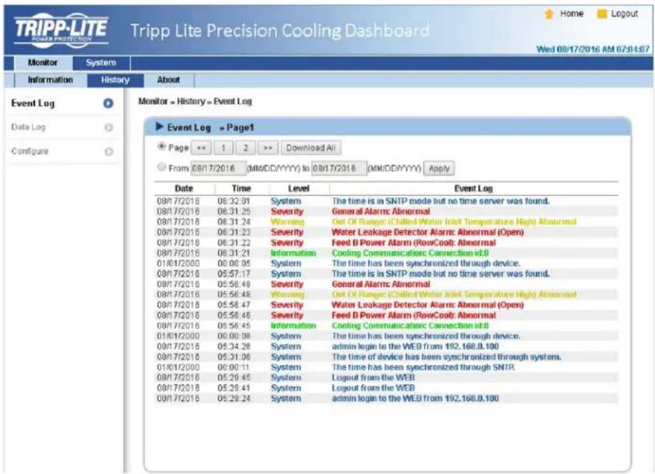
7.1.2 History
Event Log
You can query the entire event log from this page instead of from the cooling unit's LCD. All event logs can be saved as an Excel file by clicking Download All.
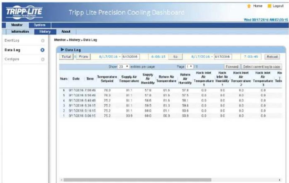
Data Log
All of the cooling unit's historical information can be found on this page. The Data Interval can be set accordingly, with the default value listed as 0 (this also indicates no record on file). Query periods can also be assigned by the user to show records within a specific parameter set for a given period.
Records can also be copied to Excel by clicking Select current to copy. From the pop-up window, press CTRL+C to copy and CTRL+V to paste all records into the Excel sheet. All recorded data will be erased when Clear History Data is clicked.
7. Precision Cooling Dashboard Software
7.2 System
The System pages are accessible only to users with Administrator privileges.
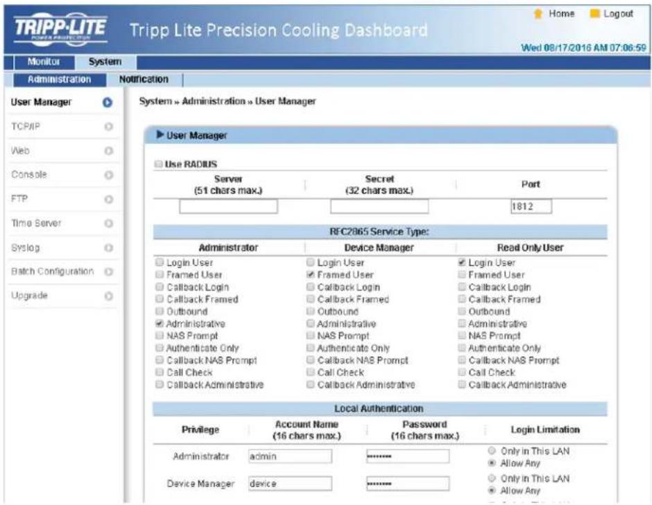
7.2.1 Administration
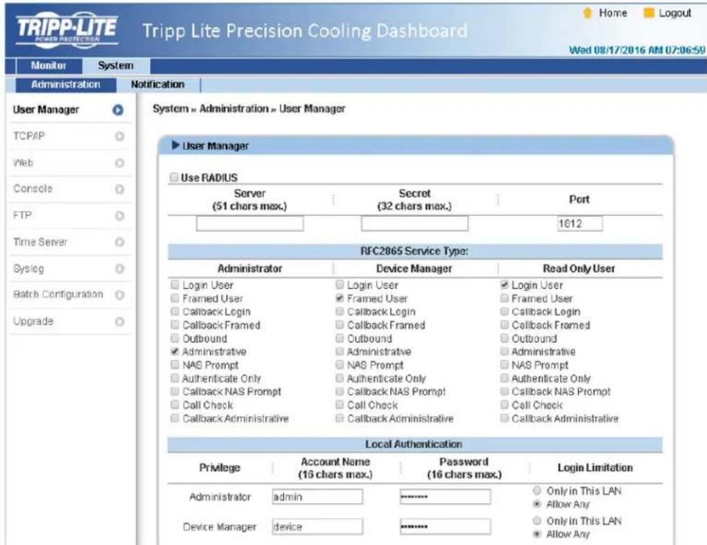
User Manager
The system supports RADIUS. Check the Use RADIUS box, enter the required Server, Secret and Port (default: 1812) information, then click Submit. The three user levels can be defined. If RADIUS is disabled, the Account Name, Password and Login Limitation can be managed via Local Authentication.
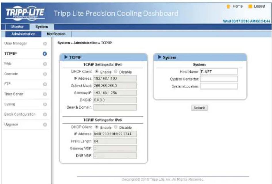
TCP/IP
7. Precision Cooling Dashboard Software
- TCP/IP Settings for IPv4
1) DHCP Client: Enable/Disable DHCP. If enabled, the DHCP server automatically assigns an IP address to the SRC00L60KCW.
2) IP Address: The IP address in dotted format.
3) Subnet Mask: The Subnet Mask for the network.
4) Gateway IP: The IP address for the network gateway in dotted format.
5) DNS IP: The IP address Domain Name Server in dotted format.
6) Search Domain: If the domain entered cannot be found, the system defaults to the Host Name.
- TCP/IP Settings for IPv6
1) DHCP Client: Enable/Disable DHCP. If enabled, the DHCP server automatically assigns an IP address to the SRC00L60KCW.
2) IP Address: The IPv6 address.
3) Prefix Length: The prefix length for the IPv6 address.
4) Gateway V6IP: The IP address for the IPv6 network gateway.
5) DNS V6IP: The IP address for the IPv6 domain name server.
- System
1) Host Name: The SNMP IPv6 Host Name on the network.
2) System Contact: System contact information.
3) System Location: System location information.
- Link
1) Auto-Negotiation: Enable/Disable automatic transfer rate (10/100Mbps) negotiation.
2) Speed: If the Auto-Negotiation is disabled, the transfer rate can be specified.
3) Duplex: If the Auto-Negotiation is disabled, the duplex mode can be specified.
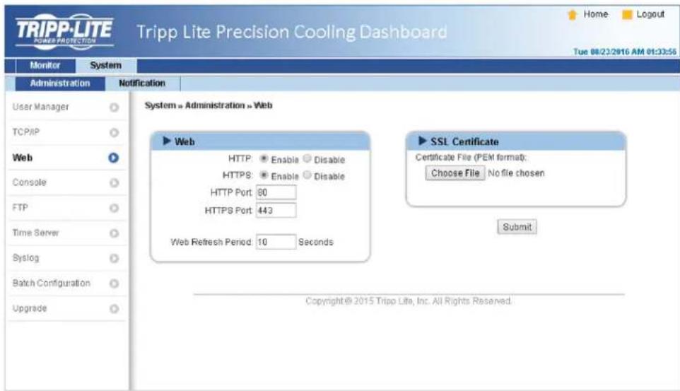
Web
1) HTTP: Enable/ disable HTTP connection.
2) HTTPS: Enable/ disable HTTPS connection.
3) HTTP Port: Assign an HTTP port number (default: 80).
4) HTTPS Port: Assign an HTTPS port number (default: 443).
5) Web Refresh Period: Enter a time period (in seconds).
7. Precision Cooling Dashboard Software
- SSL Certificate
1) To ensure connection security between the SRC00L60KCW and the connecting workstation, an SSL certificate can be used to encrypt and secure the integrity of transmitted data.
2) Certificate File: Supports PEM format which is generated by OpenSSL. Click Choose File to upload a certificate file.
Note: For more information about generating a private SSL certificate file, visit http://www.openss1.org/.
Console
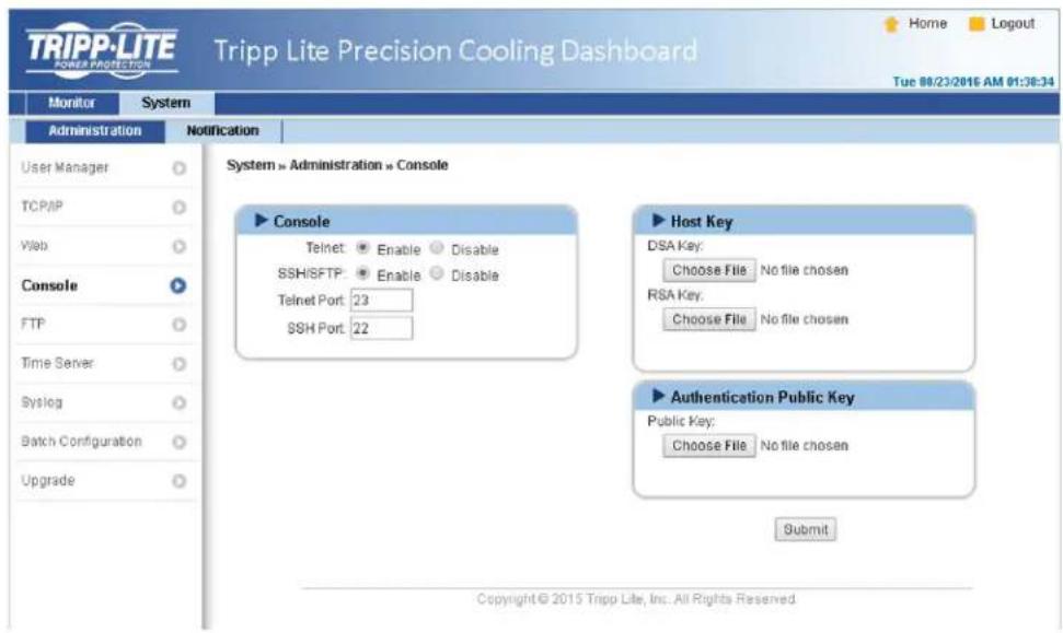
Telnet: Enable/ disable Telnet connection.
- SSH/ SFTP: Enable/ disable SSH/ SFTP connection.
- Telnet Port: Assign a Telnet port number (default: 23).
- SSH Port: Assign an SSH protocol port number (default: 22).
- Host Key/ Authentication Public Key: Supports files generated by OpenSSH, including DSA, RSA, and Authentication Public Keys.
FTP
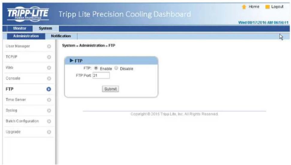
- FTP: Enable/ disable FTP connection.
- FTP Port: Assign an FTP port number (default: 21).
7. Precision Cooling Dashboard Software
Time Server
The time and date can be manually entered or automatically synchronized with SNTP servers. If the SNTP server is not responsive, the event and data log will not register even when SNTP is enabled.
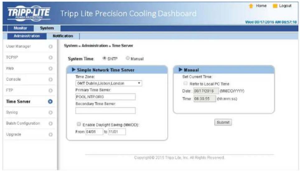
- Simple Network Time Server
1) Time Zone: From the dropdown menu, select the time zone for the location where the SRCOOL60KCW is located.
2) Primary/Secondary Time Server: Two time servers can be added. Every 60 minutes, the system synchronizes with the first responding server.
3) Enable Daylight Saving: Check to enable daylight saving time.
- Manual
If a time server is not accessible, the interface is restarted. Time and date is reinstated to previously assigned settings.
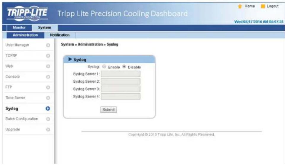
Syslog
Syslog is used to store the event log on remote Syslog servers. This will not affect the local event log. Upon selecting the Enable option, enter the IP Addresses of up to four (max) Syslog servers.
7. Precision Cooling Dashboard Software
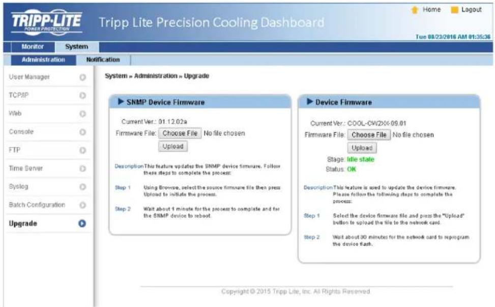
Upgrade
The Upgrade page shows the current firmware version. Click Browse to locate and select the firmware file to be used, then click Upload. The upgrade process should take about one minute.
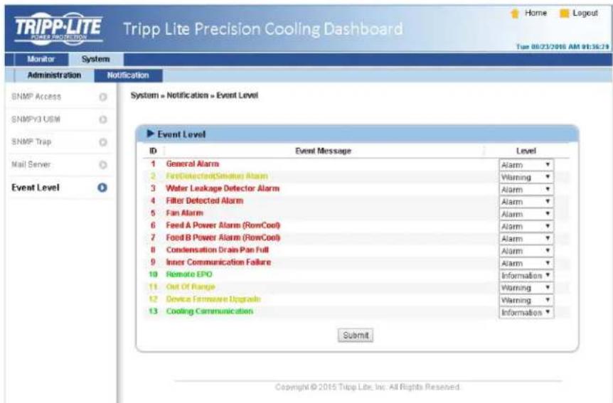
7.2.2 Notification
SNMP Access
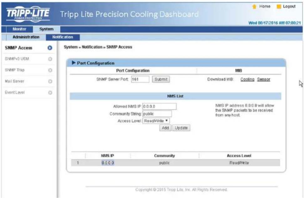
The system supports SNMP protocol and SNMP NMS (Network Management System), which are commonly used to monitor network devices. To prevent unauthorized access, the NMS IP addresses community strings and access levels for authorized users can be specified. The maximum number of IP entries is 256.
Note: If IP address 0.0.0.0 is entered, the NMS IP access restriction is ignored. The system checks the community string to identify the configured access level and permission.
7. Precision Cooling Dashboard Software
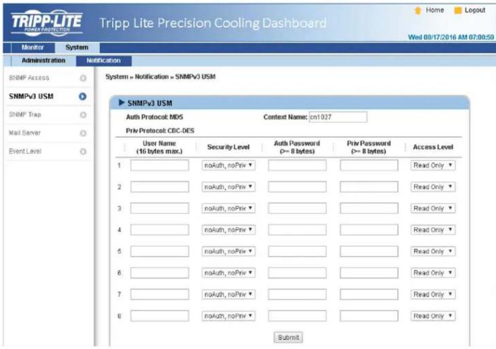
SNMPv3 USM
SNMPv3 offers features such as packet encryption and authentication to improve security. The SNMPv3 USM (User Session Management) allows assignment of eight User Names whose access is granted via SNMPv3 protocol. Their respective Security Levels, Auth Passwords, Priv Passwords and Access Levels can also be defined.
SNMP Trap
SNMP Traps alert users to specific events that occur in the monitored environment. SNMP Trap recipients must be added to the Target IP list by entering in their IP Addresses and related parameters, then clicking Add. Click the Update button to modify entries in the list. Items can be removed by clicking the Delete button.
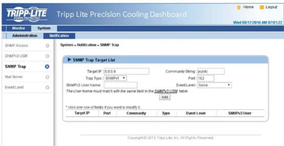
Note:
Supports SNMPv1, SNMPv2c and SNMPv3 traps. For SNMPv3 traps, specify an SNMPv3 USM User Name. Use Event Level to determine what event notifications should be sent to which Target IP Address. Five event levels are listed as:
- None: No event notifications are sent to the target address.
Information: All event notifications are sent to the target address. - Warning: Both Warning and Alarm event notifications are sent to the target address.
- Alarm: Only Alarm event notifications are sent to the target address.
- Shutdown Agent: All event notifications are sent to the target address. Go to Monitor → Information → ShutdownAgent to review your designated PC's shutdown information.
7. Precision Cooling Dashboard Software
Mail Server
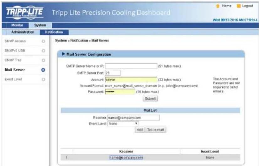
Set up an SMTP Server and specify a list of E-mail recipients who will receive notifications when events occur. The maximum number of recipients is 256.
Note: If a DNS server is not available in the network, manually assign an SMTP server address to enable the E-mail notification system.
- SMTP Server Name or IP
If a Host Name is entered, a DNS IP should be added in TCP/IP. See 7.2.1 Administration for more information.
- Account
The mail server login account.
- Password
The mail server login password.
- Receiver
The recipients' E-mail addresses.
Event Level
Select the Event Level that when triggered, an E-mail notification is sent to the corresponding recipient.
1) Information: All event notifications are sent to the target address.
2) Warning: Warning and Alarm event notifications are sent to the target address.
3) Alarm: Only Alarm event notifications are sent to the target address.
8. Optional Accessories
There are several optional accessories available for the SRC00L60KCW. Please refer to the table below for the optional accessories and their descriptions.
| Item Function | |
| SRCOOL60KTP Top pipe installation kit. | |
| SRCOOL60KWDR Water leak detection rope kit. | |
| SRCOOL60KRT Remote temperature sensor. | |
| SRCOOL60KRTH Remote temperature and humidity sensor. | |
Notes:
- For detailed installation and operation of any accessory mentioned above, please refer to the Quick Start Guide, Owner's Manual or Installation & Operation Guide included in the package of the relevant optional accessory.
- To buy any of the above Tripp Lite accessories, contact your local sales representative or Tripp Lite Customer Service.
9. Maintenance and Cleaning
Periodic inspection and cleaning of the cooling unit can guarantee the equipment to operate at optimal performance.
Internal components such as the fans and condensed water pan need periodic cleaning and inspection. This unit contains replaceable components whose cleaning and inspection should only be performed by qualified service personnel.
9.1 Firmware Upgrade
For firmware upgrades, contact service personnel.
9.2 Storage
If you do not use this unit for an extended period, it is recommended to cover the unit using the original packing material and store it in a place with well-controlled temperature and humidity (-15 65^ / 5 149^;0 95% RH, non-condensing), and free of corrosive substances, accumulated dust and pollutants. Do not place the unit horizontally or deposit external items in or on the cabinet.
Note: For more information on maintenance and cleaning, contact Tripp Lite Customer Service. Do not perform maintenance unless properly trained to do so.
10. Troubleshooting

WARNING:
The following troubleshooting actions should only be carried out by qualified service personnel. Unauthorized action may lead to severe injuries or equipment damage.
System Troubleshooting:
| No. | Abnormal phenomenon Possible cause Solution | |
| 1 | The fans do not start. The power supply is faulty. | Make sure the input voltage is within the permissible range, the circuit breaker or switch is set at ON, and the cooling unit is correctly grounded. |
| The fans are faulty. Make sure each fan is wired correctly and change the faulty fans, if necessary. | ||
| 2 | The cooling unit does not start. | Make sure the input voltage is within the permissible range, the circuit breaker or switch is set at ON, and the cooling unit is correctly grounded. |
| 3 | Forgot the password. Forgot the user password or admin password. | Contact service personnel. |
| 4 | The operation noise is too high. | Inspect and clean the fans. |
| The fan speed is too high. Check if the fans are running at full speed. Adjust the set point or the fan speed accordingly. | ||
| There is foreign matter or impurities in the pipeline. | Inspect the Y-type filter of the external piping and clean it, if necessary. | |
| 5 | LCD is functioning improperly or does not display. | Inspect the Y-type filter of the external piping and clean it, if necessary, restart the cooling unit. |
| 6 | The alarm functions properly, but the buzzer does not buzz. | The control panel wiring is correct. If necessary, restart the cooling unit. |
| 7 | The set point cannot be reached. | The control panel to enable the buzzer alarm function. Path: Main Menu → Setting → Local Setting. |
| The fans and change the faulty ones, if necessary. | ||
| Inspect the sensors. | ||
| Refer to 4.7 PID Setting. | ||
| Reduce the heat load or increase the number of cooling units. | ||
| clean the filters. | ||
| Perform the coil washing procedures. | ||
| Inspect the flow rate and temperature of the chiller (5~15°C / 41~59°F is ideal). | ||
| Repair or replace the control box. | ||
| Repair or replace the actuator. | ||
| 8 | There is standing water in the cabinet. | Use an external dehumidifier to control the data center's humidity or enable the force mode to reduce the internal humidity of the data center. |
| Adjust the water supply temperature of the chiller (5~15°C / 41~59°F is ideal). | ||
| Adjust the fan speed. | ||
| Adjust the fan speed. | ||
| Adjust the drain pump is abnormal. Confirm the drain pipe functions are normal. | ||
| If the chilled water pipeline and other pipelines are normal. |
10. Troubleshooting
| No. | Abnormal phenomenon Possible cause Solution | ||
| 9 | There is water leakage from the cabinet's bottom. | Condensed water is overflowing. | Observe if the water level in the condensed water pan is too high, inspect the condensed water pump or make sure the condensed water pipe (not bent, damaged or blocked) is correctly connected and drainage is normal. If upper piping with condensed water pump is adopted, the vertical lift should not exceed 5 m (16 ft.). |
| The pipe system leaks. Inspect and repair the leaking site. | |||
| The cabinet is not on a leveled base. | Use the levelers to level the cabinet. | ||
| The thermal insulating rubber layer of pipe is damaged. | Inspect and repair the damage. | ||
| 10 | The remote sensor signals are abnormal. | The remote sensors are not correctly located. | Inspect each remote sensor's position. |
| 11 | The three-way ball valve has no response. | The actuator is not correctly connected. | Reset the actuator. |
| 12 | Unit is unable to get on-line via the Modbus protocol. | The RS-232 or RS-485 connector is not correctly connected. | Check the connections. |
| The Baud rate setting is abnormal or the ID does not match. | Re confirm the Baud rate and ID. | ||
LCD Alarm Information and Troubleshooting:
| No. | Alarm Information Possible cause Solution | |
| 1 | Filter Abnormal The filters are clogged by foreign matter or are old. | Clean or replace the filters. |
| 2 | Drain Pan Full The condensed water pipe or the condensed water pump is faulty. | Remove the surplus water, inspect the condensed water pump or make sure the condensed water pipe (without bending, damage or blockage) is correctly connected and drainage is normal. If upper piping with condensed water pump is adopted, make sure the vertical lift does not exceed 5 m (16 ft.). |
| 3 | EPO Active Emergency shut off has been triggered due to leakage. | 1) Ensure the water leakage detector is dry and simultaneously press the▲▼ keys for 3 seconds to resume normal operation.2) If the water leakage detector cannot dry within a short time, go to Setting → Controller → Leak. Cut-Off to disable 'Leak. Cut-Off' function and follow the actions mentioned in 1). |
| 4 | Leak Active Leakage is detected. | Remove the surplus water and inspect the water level of the condensed water pan. Inspect if the drain function is normal and confirm the condensed water pipe is not bent, damaged or containing blockage. If the upper piping configuration is used, the vertical lift should not exceed 5 m (16 ft.). |
| 5 | Fire Active Fire detection is triggered. | Inspect the environment and eliminate the abnormality. |
| 6 | Smoke Active Smoke detection is triggered. | Inspect the environment and eliminate the abnormality. |
| 7 | Comm Abnormal The CAN-Link port wiring is wrong or the unit ID is repeated. | Inspect the CAN-Link port wiring and confirm the cooling units connected in series have independent and non-repeated IDs. |
| 8 | Return/Supply Sensor The air return/supply sensor is faulty or experiencing a bad connection. | Inspect the air return/supply sensor and confirm the proper wiring connection. |
| 9 | Remote Sensor 1-4 The # remote sensor is faulty or experiencing a bad connection. | Inspect the function of the # remote sensor and confirm the proper wiring connection. |
| 10 | Water In Sensor The chilled water inlet temperature sensor is faulty or experiencing a bad connection. | Inspect the function of the chilled water inlet sensor and confirm the wiring is ok. |
10. Troubleshooting
| No. | Alarm Information Possible cause | use Solution | |
| 11 | Water Out Sensor The chilled | water outlet temperature sensor is faulty or experiencing a bad connection. | Inspect the function of the chilled water outlet sensor and confirm the proper wiring connection. |
| 12 | Flow Meter The flow meter is faulty or experiencing a bad connection. | Inspect the function of the flow meter and confirm the proper wiring connection. | |
| 13 | Fan 1-8 Failed The # fan is faulty or experiencing a bad connection. | Inspect if the # fan is blocked or faulty and confirm the proper wiring connection. | |
| 14 | Ball Valve Error The three-way ball valve is faulty. Inspect the three-way ball valve. | ||
| 15 | Return/ Supply/Remote# T High | 1) The environment temperature and humidity are abnormal. | 1) Ensure the environment temperature and humidity are within the operational range. |
| 16 | Return/ Supply/Remote# T Low | 2) The alarm setting is abnormal. | 2) Ensure the out-of-range alarm setting is correct. |
| 17 | Return/ Supply/Remote# RH High | 3) The temperature sensor is faulty. | 3) Inspect the temperature sensor function. |
| 18 | Return/ Supply/Remote# RH Low | 4) The load is too large. | 4) If the temperature is still too high after eliminating the above problems, confirm the load does not exceed the cooling capacity of the cooling unit. |
| 19 | Water In T High 1) The temperature or flow rate of the chilled water supplied by the chiller is abnormal. | 1) Inspect the temperature and flow rate of the chilled water. | |
| 20 | Water In T Low | 2) Ensure the out-of-range alarm setting is correct. | |
| 21 | Water Flow High | ||
| 22 | Water Flow Low | 2) The alarm setting is abnormal. | |
| 23 | Run Over Hours The periodic maintenance has not been performed. | To guarantee the normal operation of the system, perform maintenance immediately. | |
| 24 | Leak Wire Open The water leakage detector is not correctly connected. | Inspect if the water leakage detector is loose, in bad contact or broken. |
Note: If the alarm still goes off after the above possible causes are eliminated, please contact Tripp Lite Customer Service.
Appendix 1: Technical Specifications
| Model SRCOOL60KCW | |
| Phase/ Frequency/ Input Voltage 1~, 50/60 Hz, | 208-230V ± 10% |
| Max. Power Consumption 2.41 kW | |
| Rated Cooling Capacity * 43.4 kW | |
| Max. Cooling Capacity ** 59.1 kW | |
| Air Volume 7500m³/h (264,860 ft. | 3/hr.) |
| Rated Chilled Water Flow Rate 80 Lpm (17.6 gal./min.) | |
| Pressure Drop 98 kPa | |
| Drain Pump (Optional) Flow rate: 5 L/h (1.3 gal./hr); Rated vertical lift: 5 m (16 ft.) | |
| Display HMI: LCD 64 x 128 pixels and four LED indicators | |
| Max. Return Air Temperature 50°C (122°F) | |
| Max. Water Inlet Temperature and Pressure 22°C (72°F), 5 kg/cm | 2 |
| Operational Audible Noise | 88 dB A @ 4,400 CFM |
| Operating Temperature 4 ~ 50°C (39 ~ 122°F); 30 ~ 85% RH, non-condensing | |
| Storage Temperature | -15 ~ 65°C (59 ~ 149°F); 0 ~ 95% RH, non-condensing |
| Dimensions [Width x Depth x Height] | 300 x 1090 x 2000 mm (12 x 43 x 79 in.) |
| Net Weight | 187 kg (412 lb.) |
Notes:
- Refer to the unit's rating label for the safety rating.
-
All specifications are subject to change without prior notice.
-
Testing conditions for rated cooling capacity:
Return air temperature: 40.6°C DB/ 21.6°C WB/ chilled water inlet temperature degree: 7°C/ chilled water outlet temperature degree: 15.8°C.
** Testing conditions for the maximum cooling capacity:
Return air temperature 48.9^ DB/ 23.9°C WB/ chilled water inlet temperature: 7^/ chilled water outlet temperature: 15.4^
Appendix 2: Periodic Inspection / Maintenance List
Monthly Inspection/Maintenance List
Date: Model: By:
| Environment inspection | |
| The cooling unit is installed in? | |
| Is it free of dust and surplus moisture? | ☐ Yes / ☐ No |
| Is the cabinet appearance without damage? | ☐ Yes / ☐ No |
| Supply air temperature | degree (s) |
| Chilled water outlet temperature | degree (s) |
| Supply air set point | degree (s) |
| Can the cooling unit reach the set point? | Yes / No |
| Internal inspection | |
| Are there any impurities or foreign matter in the condensed water pan? | ☐ Yes / ☐ No |
| Do the filters function well? | ☐ Yes / ☐ Replacement or cleaning is needed |
| Does the water in the condensed water pipe flow smoothly? | ☐ Yes / ☐ No |
| Do the fans function normally and rotate without interference? | ☐ Yes / ☐ No |
| Does the drain pump function normally? | ☐ Yes / ☐ No |
| Be sure to disconnect the input power before making the following inspections. | |
| Are the electrical joints stable and free of foreign matter? | ☐ Yes / ☐ No |
| Does the input power match the rated value of the cooling unit? | ☐ Yes / ☐ No |
| NOTES: | |
| Signature: | |
Please copy this page for use during the inspection/maintenance procedures.
Appendix 2: Periodic Inspection / Maintenance List
Quarterly Inspection/Maintenance List
Date: Model: By:
| Cleaning: Clean the following components. Use an air gun, if necessary. | |
| Filters (replace if necessary) | □ Completed / □ Replaced |
| Front/rear doors and side panels | □ Completed |
| Be sure to disconnect the input power before cleaning the following components. | |
| Condensed water pan | □ Completed |
| Condensed water pipe | □ Completed |
| Fans | □ Completed |
| General inspections | |
| Is the water supplied by the chiller normal? | □ Yes / □ No |
| Does the alarm system operate normally? | □ Yes / □ No |
| Does the unit operate normally in all modes? | □ Yes / □ No |
| NOTES: Signature: | |
Please copy this page for use during the inspection/ maintenance procedures.
Appendix 3: Glycol Correction Table
| Item Glycol type | Adding proportion** | ||||||
| 0% 10% | 20% 30% | 40% | 50% | ||||
| Cooling capacity * | Ethylene | 1.00 0.96 | 0.89 0.81 | 0.73 0.65 | |||
| Water-side pressure drop* 1.00 1.04 1.11 1.17 1.25 | 1.34 | ||||||
Note:
The correction parameters are based on the correction values under the following working conditions:
Return air temperature: 29.4^ DB/ 18.1^ WB; air volume: 4930m^3/h ; temperature difference of chilled water 7.2^ ; chilled water flow rate: 62 Lpm.
- Multiply the values read from the unit by the above parameters and the results are taken as the corrected cooling capacity and water-side pressure drop.
** The maximum brine adding proportion of the unit is 50%.
Appendix 4: Warranty and Product Registration
2-Year Limited Warranty
u
THIS WARRANTY DOES NOT APPLY TO NORMAL WEAR OR TO DAMAGE RESULTING FROM ACCIDENT, MISUSE, ABUSE OR NEGLECT. SELLER MAKES NO EXPRESS WARRANTY OTHER THAN THE WARRANTY EXPRESSLY SET FORTH HEREIN. EXCEPT TO THE EXTENT PROHIBITED BY APPLICABLE LAW, ALL IMPLIED WARRANTYES, INCLUDING ALL WARRANTYES OF MERCHANTABILITY OR FITNESS, ARE LIMITED IN DURATION TO THE WARRANTY PERIOD SET FORTH ABOVE; AND THIS WARRANTY EXPRESSLY EXCUSES ALL INCIDENTAL AND CONSEQUENTIAL DAMAGES. (Some states do not allow limitations on how long an implied warranty lasts, and some states do not allow the exclusion or limitation of incidental or consequential damages, so the above limitations or exclusions may not apply to you. This Warranty gives you specific legal rights, and you may have other rights which vary from jurisdiction to jurisdiction).
Tripp Lite; 1111 W. 35th Street; Chicago IL 60609; USA
WARNING: The individual user should take care to determine prior to use whether this device is suitable, adequate or safe for the use intended. Since individual applications are subject to great variation, the manufacturer makes no representation or warranty as to the suitability or fitness of these devices for any specific application.
PRODUCT REGISTRATION
Visit www.triplite.com/warranty today to register your new Tripp Lite product. You'll be automatically entered into a drawing for a chance to win a FREE Tripp Lite product!*
- No purchase necessary. Void where prohibited. Some restrictions apply. See website for details.
Regulatory Compliance Identification Numbers
For the purpose of regulatory compliance certifications and identification, your Tripp Lite product has been assigned a unique series number. The series number can be found on the product nameplate label, along with all required approval markings and information. When requesting compliance information for this product, always refer to the series number. The series number should not be confused with the marketing name or model number of the product.
WEEE Compliance Information for Tripp Lite Customers and Recyclers (European Union)

Under the Waste Electrical and Electronic Equipment (WEEE) Directive and implementing regulations, when customers buy new electrical and electronic equipment from Tripp Lite they are entitled to:
- Send old equipment for recycling on a one-for-one, like-for-like basis (this varies depending on the country)
- Send the new equipment back for recycling when this ultimately becomes waste
Tripp Lite has a policy of continuous improvement. Specifications are subject to change without notice.


1111 W. 35th Street, Chicago, IL 60609 USA www.triplite.com/support
| Modo Ganancia | Restaurar** | Derivativa** | ||
| P tau/ (Td x G*) | ||||
| PI 0.9 tau/ (Td x G*) | 0.3/ Td | |||
| PID 1.2 tau/ (Td x G*) | 0.5/ Td 0.5 Td |
| +-----------------------------------+ | |
| TCP/IP Setting | | |
| +-----------------------------------+ | |
| [1].IPv4 Address: | 172.18.48.215 |
| [2].IPv4 Subnet Mask: | 255.255.255.0 |
| [3].IPv4 Gateway IP: | 172.18.48.1 |
| [4].IPv4 DNS or WINS IP: | 172.18.0.18 |
| [5].DHCPv4 Client: | Disable |
| [6].IPv6 Address: | fe80::230:abff:fe28:2e67 |
| [7].IPv6 Prefix Length: | 64 |
| [8].IPv6 Gateway IP: | :: |
| [9].IPv6 DNS IP: | :: |
| [a].DHCPv6: | Disable |
| [b].Host Name (NetBIOS): | TLNET |
| [c].System Contactor: | 10th Floor |
| [d].System Location: | 10th Floor Testing |
| [e].Auto-Negotiation: | Enable |
| [f].Speed: | 100M |
| [g].Duplex: | Full |
| [h].Status Stable: | 3 |
| [i].Telnet Idle Time: | 60 Seconds |
| [0].Back To Previous Menu | |
| Please Enter Your Choice => | |

Tripp Lite Precision Cooling Dashboard Login
Copyright © 2015 Tripp Lite, Inc. All Rights Reserved.
Notas:
1111 W. 35th Street, Chicago, IL 60609 USA • www.triplite.com/support
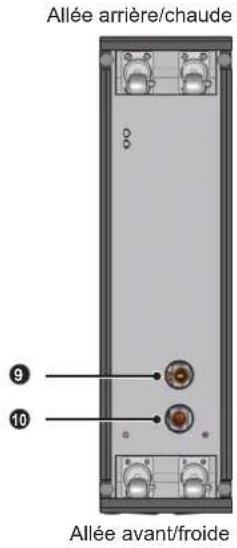
(Figure 2-2:Vue avant) (Figure 2-3:Vue armere)
6. Configuration Web/SNMP
6.1 Configuration SNMP
6. Configuration Web/SNMP
6.1.1 Configuration via l'interface Web
6. Configuration Web/SNMP
6. Configuration Web/SNMP
6. Configuration Web/SNMP
6.1.4 Configuration via le port COM
6. Configuration Web/SNMP
6. Configuration Web/SNMP
Paramétrage TCP/IP
| +-----------------------------------+ | |
| TCP/IP Setting | | |
| +-----------------------------------+ | |
| [1].IPv4 Address: | 172.18.48.215 |
| [2].IPv4 Subnet Mask: | 255.255.255.0 |
| [3].IPv4 Gateway IP: | 172.18.48.1 |
| [4].IPv4 DNS or WINS IP: | 172.18.0.18 |
| [5].DHCPv4 Client: | Disable |
| [6].IPv6 Address: | fe80::230:abff:fe28:2e67 |
| [7].IPv6 Prefix Length: | 64 |
| [8].IPv6 Gateway IP: | :: |
| [9].IPv6 DNS IP: | :: |
| [a].DHCPv6: | Disable |
| [b].Host Name (NetBIOS): | TLNET |
| [c].System Contactor: | 10th Floor |
| [d].System Location: | 10th Floor Testing |
| [e].Auto-Negotiation: | Enable |
| [f].Speed: | 100M |
| [g].Duplex: | Full |
| [h].Status Stable: | 3 |
| [i].Telnet Idle Time: | 60 Seconds |
| [0].Back To Previous Menu | |
| Please Enter Your Choice => | |
6. Configuration Web/SNMP
Serveur de temps
Tripp Lite Precision Cooling Dashboard Login

Copyright © 2015 Tripp Lite, Inc. All Rights Reserved.
Remarques :

Manufacturing Excellence.
1111 W. 35th Street, Chicago, IL 60609 USA • www.triplite.com/support
PykoBODCTBO NOIb30BaTeJa
SRC00L60KCW
BHytpnpaHbI ppeu3noHHbI KOHdNcNoHep C BoJHbIM OxJaXdeHneM
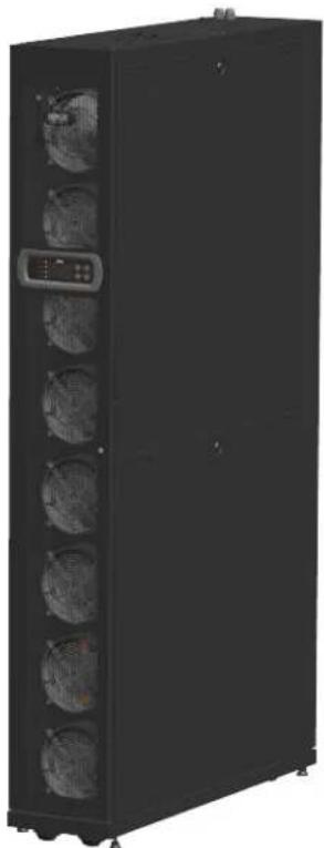
English. 1
Espanol. 60
Francais. 119


1111 W. 35th Street, Chicago, IL 60609 USA - www.triplite.com/support
OxpaHaeTc ABTOPCKM npabOM © 2016 Tripp Lite. Nepeneuatka Zanpeuaetra.
CopepxaHne
1. Baxhblye yka3aHnno TeXnke 6e3oNaChocTn 180
1.1 PpEynpeKdEHH no pa3MeueHH 180
1.2 PnpynpeKdEHH no noKnIOeHH 180
1.3 PnpdynpexkdeHn no nnoB3oBaHn 180
2. BBeJeHne 181
2.1 BboHna HnΦopMaunrOb n3denn 181
2.2 ΦyHKUIM IN BO3MOXHOCTN 181
2.3 ynapoBOyHbIJIiCT 182
2.4 BHeuHmBd 183
2.5 Cxema pacnoJoxHeNIA KOMNoHEnTob 183
2.6 CnCTema Tpy6oPBOOIOB 185
2.7 Panaelb ynpablenna 185
2.8 Be6/SNMP-KapTa 186
3. YctaHOBKa 187
3.1 MecTo yCTaHOBKn 187
3.2 Pa3meueHne 187
3.3 IepemeueHne 188
3.4 PachnojoxeHne 188
3.5 CHaTne 60KoBoi naHenn 190
3.6 BbCbePnBaHne oTBePcTn 191
3.7 BHeuHne Tpy6OpOBoDbl 192
3.8 IopKnIooHHe K 3JIeKTPoPiTuHaHIO 193
3.8.1 3neKtpoNTaHme 193
3.8.2 KOndHcatooTbOHa TaTy6Ka 196
3.8.3 196
4.3 PpOyBkA Tpy6oPpObOa CnCTeMbI OxJAAKeHn 198
4.4 Pa6ouaTempeaTypa N BlaxKHOCTb 199
4.5 TeTeKToP yTeuKn BoDbl 200
4.6 Bodnbl 6aanaHc 200
4.7 UCTAHOBKa npamaTePoB IND-ynpabEnHn 201
5. 3Kcnnyataua 203
5.1 Iepapxna KK-dncnne 203
5.2 Φунциониюваиме панени упавлени.. 204
5.3 3KpaH cTAtyca nIraBHOe MeHIO 204
5.4 IpoBepka npab doctyna n BxO B cnCTemy 205
5.5 Pa6o7e peKmbl 205
5.6 0TKIOUeHnE 206
5.7 HacrpoKn KOnmnoHepa 206
5.7.1 UctaHOBnEHoe 3haueHne 206
5.7.2 IokaJIbHaHa NaCTpOJa Ka 206
5.7.3 HacTpoJa KOHTpOJIpepa 208
5.7.4 HacrpoKa CmHaJIaauuM 208
5.7.5 IpoCmOpT cTaTyca CnCTembl 209
5.7.6 IpoCmOTp/c6pocnHΦopMaun O BpeMeH pa6oTbI.....210
5.7.7 Ppocmotp/ounctka Jyphana co6bItn 210
5.7.8 N3mehme Tuna CNTembl 210
5.7.9 BocctaHOBHeHne HactpoeK no ymouHaHIO 211
5.7.10 HacpoKa pexnma aBtOMaTneckoro ynpabneHna....211
(Puc. 2-2: Bud cnepedu) (Puc. 2-3: Bud chuzy)
IpeepnepeMeeHem o6opyoobAHnK MeCy yCTaHOBKn Heo6xOJMo CnnaHmPoBaTb MappyrCOrnaCHO cneyouuymyka3aHnM:
1 Y6eHNTcB b TOM, TTO npoxoN, non, nHOT mHn naHyc, HaxOaJmecHa MapwpyTe nepMeueHHa, CnoC6Hbbl BbIepKbBaTb Bec 06OpoyoDaHHa NIOBcEMHO-TpAHCnOPTHOro npCHNOcO6NeHHa, a TaCKe IMeIOT DOCTaTOHcBO6DHoro npOCTpaHCTBA BO I36eKaHHme CTONKHOBeHHM.
2 Pn HauHnHaKlnoHoro yuaCTka Ha MapuPyTe nepMeueHn erO yron HauNoHa He dOnJKe npeBbIaTb 15 rpaIycob.
3 PONIKI, PnIKPENIIHHe K HIXKHe NOBEPXHOCTN YCTPOINCTBA, MOrYT NcNtB3OaTbCA TOLko IINNEpeMeEHN HA KOPOTKHe paccTOHnIA. IJIe NEPEMeUeHNHa DInHHBe paCCToHnA cNeJyET NcNtB3OaTBIOITbMHO- TpaHCNOptHO npCnOco6JeHne (Tnna BnIOuHOro nOpyu3nka, N3O6paKeHOrO Ha PNC.3-2) BO N36ExKaHne NOBpeKeDeHNPONIKOB.
4 Yka3aHbIe poNkMOry TcNoBb3oBaTcB TaToBko DnpeMeueHnno rnaKo noOBepxHocTHn. He cneJyET NcNoBb3oBaTb DnpeMeueHn yCtpoCTBa No HEPBOHOMY OCHOBaHNO, NOCKOBky 3TO MOKeT pINBeCTN K NOBpeXdEHNO poNkOB IN BepoTHMOI OIPOKMbIBaHNO yCtpoCTBA.
5 Pn npnepeeHn yctpoCTBa cnyeT yHtBbTa erO BbcOTy n pacnoNKeHne CEHTpa TAKeCTn.ДЯ 06ecnueHn ONTMalbHn 63oNaCHcTn npn nepeMeHn yctpoCTBa OHO DOnKHO OcyuEcTBaTcCnAm Ka K MHHMym DByx YelOBek.
BbipabHbuaoune npncno6beHHa
IocyeUcTaHOBKyUcTPOHCTBa HnpeDInonAraeMoE MeTO HeoXoHMO OecneuHTb Eero UcToHBOCTb NytEm BpaueHna YteBpEx BBpaBHBaOuix npCnOco6BHeHn No cAcobos CTpeKe CnOoub ToaeHOro KIOHa. YbeMTEcb BTOM, yTO UcTPOCTBO He nepeMeuaetca CamOpnp3BOJbHO Hn Keaayetn CTOpBOH B CTOpOHy.

BHUMAHNE!
BbipabHbauoue npncoc6nne Hcnoh3yotc TOnko DnBbipabHbHaH yctpoCTBa HmOry HcNoh3oBaTcDnKOMneHcaunpepenada Bbcotblnona.
3.4 PacnoJoxKeHne
Iocne npemeeHn yctpOCTBa Ha MeTo H er oY cTahOBKn npaannenbHO KOpNcY COeHrero YcTpoCTBa CneDyET oBecneHTb er oYcTouHBOCTb. B3abNCIMoCTn OT KOHKpeTHOro MeCTa YcTahOBKn Ira TTOr MOrY NcNObl3OBaTbCRA cNeDyUuue Dba cnoc6a:
Ppncno6beHnna Pkcaunn Kopnyca
KaJdbKoHdNtUHeP KOMnEeTcA YeBpMbMa COeINHTeBbHM NJIeMeHTaMn (DbymC nIeBOy N DByMa C TbIbHO CTOpNoB). PpeB BblOnHeHMe COeINHeHm C NIOb3ObaHMe DaHHbx 3NeMeHTOB CHMMTEpeDHIIO U 3aHIIO DBepCu. IpnOHbOHTe DeckTBMA B CnElyuOe MnpAKe:
1 EcnnepeHnA Dbepua 3anepta,Toe e neyet otneptb npnlaaoMcKnoohm.
2 OToeHNHTe NnOckn Ka6enb NaHEnyynpaBHeHn 3a3eMnaHOuN npBOD ,noHMnTe nepeHHoDBepy U n CHIMITE ee.

(Puc.3-2:IpepeueeHue C uicnoBtOBAHue BUNo4HO 0n2py3uHa)
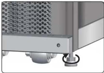
(Puc.3-3:Pezymnpo80nBHe HOKKU)
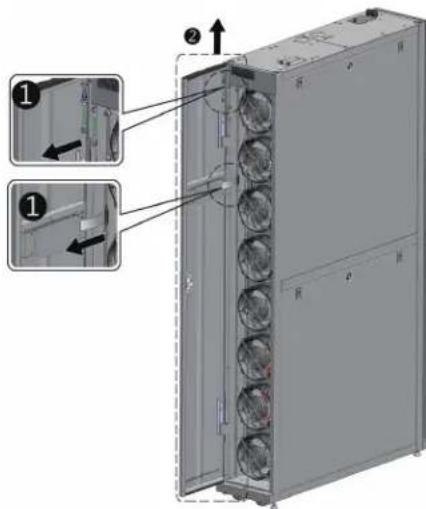
(Puc.3-4:OmkpbmbaHue nepedneDbeoepuB)
3.YctaHOBKa
3 C NOMOUIIOBTOBPTKMBBIEBHNEITDABAHNTAIOCTOEINHITNPBOOD3aEMJIENHO 0TADHEIBEPB1,OTKIOHHTE 3aIHIOI BEPU, a3TEMOTAHNTEEBBPx2 HCHMNTe ee.
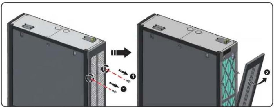
(Puc.3-5:Cnmaue zadneu dabeu)
PumueaHue. Pocne Chmua nomecumme nepedno 13adno 0eepb6 63oanchoe meo 60 u36bae Hae nopekdo hua oopoyobua uu HAeehnmpa6 m 6 peynmame 8amokhbo cmoKhoenhu
4 C nOMOJIbIO OTBEPKIN OCSaBBe NHHM BnH T KpeJIeHn HmKcNpyUeI npCnOc6JIeHn I npKpEInTe erO K KopnyC ycoedHe rY cTpoCTBA.
(KoHmuahep) (Kopnyc cocdHero yctpoictBa)

(Puc.3-6:CoedunHeue KOnduuHoeepa cKopnycom Cocedehezoycmpoucmba)
5 CkpenHne npednne H 3aHnne FHKCNpyoou nprncno6bneHn (BCero 8 wT.) c Kopnycom cocedHero yctpoiCTBA.
6 Pocne 3akpenenHn fKncpuyuux npncno6nenn yctaHOHTe nepeHIO u 3adHIOBepbHa cBOH MeCTa.
3.yCTaHOBKa
yapedkmbaiooee kpenneHne
YepKmbaoue KpeHnne (KpOHteH) nCnoB3yETcna fMkcaun yctpoCTBa KOHNIOHOPOBAHnHa NODOHE B IPOUCCE TpaHCNOPTMPOBKN. 3OT KPOHTeH TAKKE MOKET nCnoB3oBAbCraIg KpeHnne YcTPOCTBA KOCHOBAHnIOncpe pAmeueHmB 3daHHOM MecTe.
1 DByMa BnHTaM M6 npKpEnHte yepKnaHOe KpeNHe H pAme nepneHne DBepe (BbctyNaoue qactbBo Npe) 1
2 PnKpEnIte BbCtynaoJyUoAcbK Nony npn moOnu BmHTOB-Camope3OB 2.
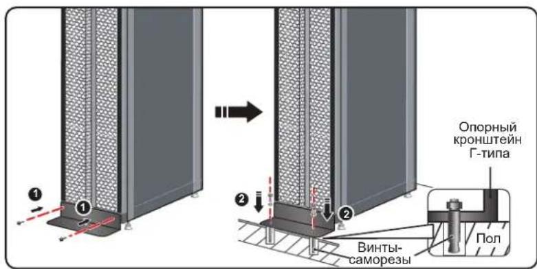
(Puc.3-7:YcmaHoaKaΓ-Obpa3HoI onOpby nOa nOoepjxua paHoeecua)
3.5 ChTne 60KOBoi nHaEni
Ecn60koBaa naHnB 3aepTa, to ee cneyet otnpetb npnaarouimmc KIOUOM. Ha kaxdo n3 dbyx 60kOBbIX naHene NMEOTcno DBe 3aueKNI. OndobpeMeHHo HadaBte Ha 3aueKIN BHN3 CHMNTe 60KOByo naHnB.
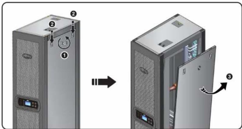
(Puc.3-8:Chamue6okoboi nahan)
IyCTaHOBKn 60KOBn NaHeNn Ha MeCTo COBMeCTHe Da HmKHNX OTBepCTn OODHOBpeMeHHo HaDaBnTe Ha3aUeKNn NO HanpaBneHHO BnH3.
3.YctaHOBKa
3.6 BbCBePnBaHne OTBepCTn
PocBepnIte OTBepTm B aJIbHIOIe IINI NOIOnke B 3ABNCMOCTN O T CNOCoBA NOBDOK: CHM3Y (3aBOIDCKA KOMIINEKTaU) INN CBepxY (C NcONb3OBaHHem PPODABaEMOOTENBHO KOMIINEKTARSCOOIL60KTP).
IpybnpoBOD o6epHyT BHeHUM Cnoem TEnnO30aun DnA yMeHbWeHNA CTeneHH BnnaHNA TeMnepaTypbI HApxKHO Bo3dyxa H BO 36eKaHNE KOHeHCAUN BObl. IuaMetp OTBepCTN DOJKeH coCTabNt bOkono 13 MM.
Pa3Mepb: [MM] IIOMbI
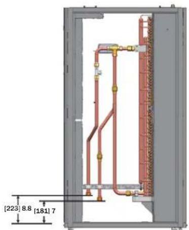
(Puc.3-9: Cxema paonoknemma pmybop08o0e npu huknei no6doke u ycmanoh04he pa3mepb)
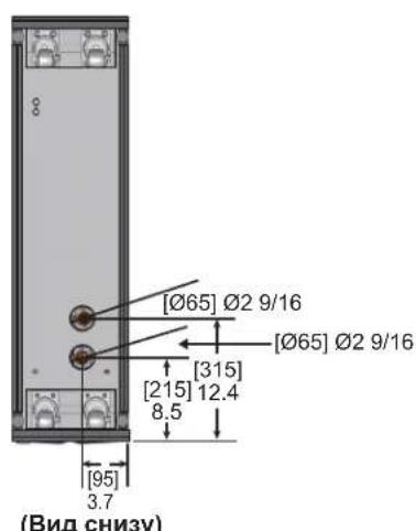
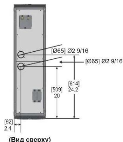
(Puc. 3-10:ДuaemempuUpacnoLoKeHneOmeepcmuiDnHuxHeNo8oOkmpmy6bnpo8o08)
Ppmeue. nnoo0okm npboosoe noodau oxakdo hou 6b8 cyepx kmoanua Tripp lte npocmaaem konnnk mohmaxa mypboosoo SRCOOL60KTP (npdaemcm odneho).
3.yCTaHOBKa
3.7 Bheunne Tpy6oNpOBoIbI
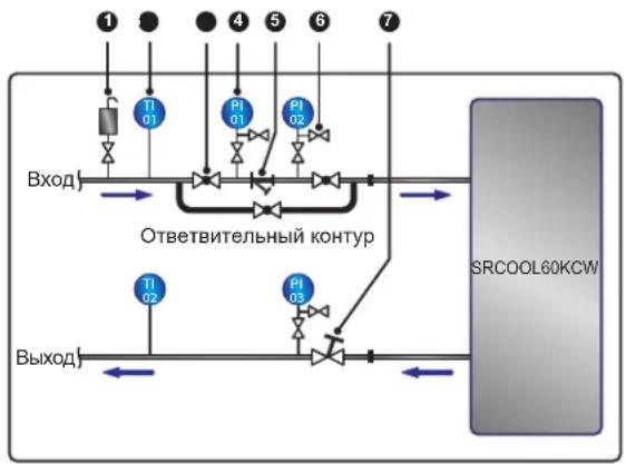
(Puc.3-11:PEKOMeHdyemar cEmo ycmatoHbKu eHeWnux mpybonpoeodob)
IpoKJIIOUHTe BHeHmI Tpy6OpOBoD cABToMaTWeckIM BbInyCKbHM KnaHApOM 1 K BoO3a6OpHMy KOHcy (KaK POKa3aHO Ha pnc. 2-5) IJy ydaJIeHnBaO3dyxa m3 Tpy6OpOBoDa.
YCTAHOBHTe HnBTP Y-06pa3HOrO TnPa 3 BO BnYcKHom Tpy6oNpBODe Ia HmNbTpaun 3aqrpa3HeHm N XmMnueCkX BWeIeCTB, HaxOJIAuXxCBa BOte. YCTAHOBITE uapOBoi
KlaanepnIbTpOMY-06pa3HOroTINnNnIOaHneroHrOaCOnAHHoNTBtBHeHOKHTpya.IpneHo6xoIMOCCTNOCHTKnNpeMOHTaΦnBtpa3akpoTseapobOKNlaanDnToTOx06bOxnaJENHHaBOaNoCTyanaBvCTPOCTBOKOHdUmOHPOBaHHaYepe3OTBtBHeBbHkoHTpyBoH36eKaHHeNtOpebOTPlekpaeeHHnoDaAH.YctahOBtMeHometp
4 neped mY-6b3nHO Tmna nocne Hero cIeBIO6hApyeHn BO3MOxHn 3aKynOpKn 13-3a nepenada daBleHnM.
YCTAHOBHTMEHMOFOyHKUHOHaBbHy ypaBHNTbHbBEHTMb7 Ha BOOBOblcHOM KOHcIe IapeyHnPoBaHIn paXoDa Otpa6ToHHo BObI.
IpombikTaTpy6oPBoOob
Ira o6ceueHn BbCOH 300eKTHBHOCTN OxnaKHe HNO3OIOH NPOIN3BOIDt POMBIBKY Tpy6oPBOOB C CEJbY ydaHn HXMnuecknx BeueCTB. Ia nPOMBIBKN TP6oPBOOB INONBJyTe IaHrC CEJIb 3aKOpaUMBAHn KOHTpya H NaPpAbeHn OXnaJcHHO BDOBy HeNocpeCTBeHHO OT BYNKHO K BOByNCKHO MOKUy K BInyCKHO My KOUY 6e3 npoxKeHn CheE3 KOHNIOHep. Ia Fmbltpaun MeKnX pImMeCEe CneYET HcNOB3OABt Fmbltp Y-6Opa3HOrO Tnua C FmbltpyUOnm 3JeEMeTMOT ToHKoOHCTKN (peKOMeHdyembl pa3Mep ayeek: 20).Iio nCTeEHn 12-24 acob cipkyanu BoBb IB Tpy6oPBOADx CneYer pOn3BOIDt ZmeHy fMbtp rpy6o OHCTKN (peKOMeHdyembl pa3Mep ayeek: 3).
PnncnoB30OBHnnr nnKoNEbO npcaDN Cm. PnploKeHne 3 "Ta6nua KoprpeKtpOBKn cOepxHaN rknokn" Tne pndTabHeHa HOpmaun o6 oxnaJdaIOe cnoc6HOCTn n pepeaX daJIeHn C BOAnOH CTOPBOH.
3.YctaHOBKa
3.8 IopknIOueHnK 3JNEKtpoNTaHnIO
IpumeyauHa:
- Napamempb6xbozo numaHua doonKbH coombeimcB08aMb HOMuHaJIbHIM 3NaueHUM, ykaaONHbM Ha nacnpmoHm ma6nueke ycmpoCBA.
- Poknue Hc Kcmouhky bdo humna nocpecmom 2ubko zhypurae3 kabeymyk ydn ond nocknoehu cnyedym uonbtaombubukuyhp, bnoenb B homeknnmpy U (muna SIT dma cpan Ceepoh Amepuu npaohoeHHdu aon ppaH Eponby); 2,5 MM2/3C (12 AWG/3C); MuH. 300B; MuH. 90^, BOMNKeMc kabeHou mynkoi dne coeunnua
- Makumahna homnebma moohocmb houuohepa coombaen 2400 Bm. ymanobme coomeemcmyuab mowamuecku bkynmoanm, eknoeHHb H omenknaympy UL (pekomemdymbe napammpb: 6oee 300B~, 20A u 2P) un pahocehnh dna cpan Eopnb, ha xode ycnpcmba c eibto 3auumby dpyzoo obopyoohua, haxodaezoe 8e 20 konHmype, npu 803huhoehnu nepepy3ku unu kopomko 3ambikaiua.
- Ppu KOHMPBKe BuHMo, uONbEyMbx dna MOHMAKApnoBodku 8 bne 3aKUMOB numaHua, npumehnue pekOMeHyOme yucuane 12,2 Kc:cm
- Ppu omycmcbu npoboda, npoxoaezo uee3 kabe-b-kanan dna cnaobomouho npobodku b cepkne yacmu kopnyco, 3akpoime kabe-b-kanan 3aanyuou, nocmabnemou b komnke me ochacmku, bo 136exahue cokonheny npiu.
- Dnna npoboda mexdy moekui zadeiku u hypa u 3axumamu dojka 6bmtb makoi, ymobs b cyuee bckalb6bohua hnu ypa u3 zadeku hamkene mokohecuyux npobodnpoucxodu do 3aemnoe npobodnka.
OINHOHbI BXoD
1 NotaHMe BBePx 3a pyKy 1 H CHMHTe 3aRnyuKy Ka6eB-KaHana DnA CNIOBOI npoBOKn 2 B 3aJHe qACh T BepXHe NaHEn KOpNycA.
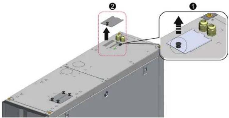
(Puc.3-12:Chamue 3a2nyukKa6eb-kahana cunoob npo8odu)
2 C nOMOuBIO KcayueK ydaHnTE Bb6BHBte 3aIyUKN1, DocTaHbTe Ody Ka6eBHyTOB TYkN 13 KOMINNEKTa OCHACTKN, OTBePHTE raKy Ka6eBHO BTyIKN 2, a 3aTEM C nOMOuBIO ToT raiKn npKpENITE Ka6eBHyTOB TYk N 3aYUkne I npToHnTE CnNOByIO npoBOkypeE Ka6eBHyTOB TYkN 3.
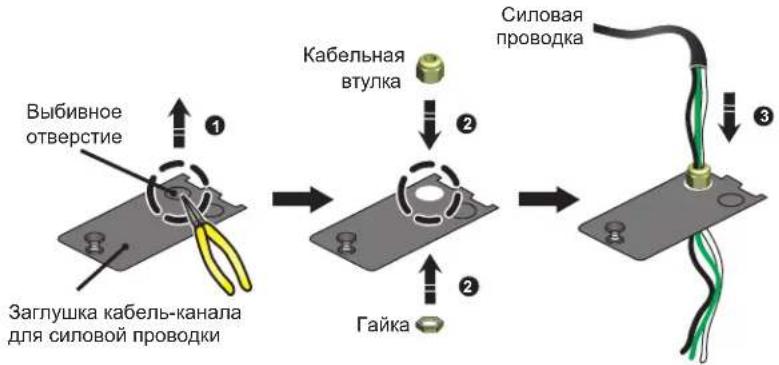
(Puc.3-13:Пообдевенue cunobod npoobodku)
3.yCTaHOBKa
3 CnOMOIOBTOBETKNOcna6bte BnHTb6NOKaMOHTaXkbix 3axmOB IN CnOMOIOBKOJIbceBbIX 3axmOB 3akpenite npoBaD a 3axmMax1,2n5.
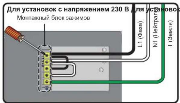
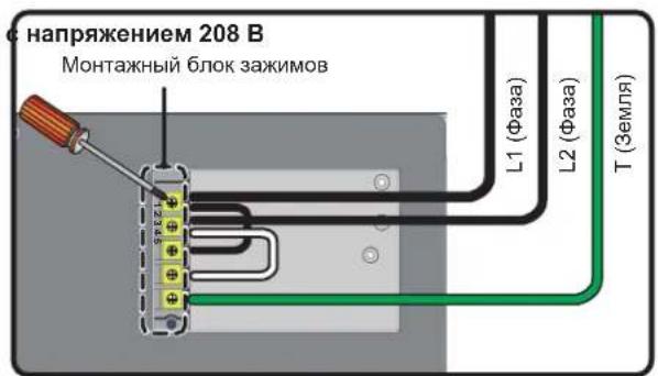
(Puc.3-14:Mohmaz cunobod npoeobodu)
4 UCTAHOBHTA Me cTo 3aTnykky Ka6eNb-KaHana CNIOBn npOBOKn H nIIOTHo 3aBePnTe Ka6eBHyTO BVtNYK.
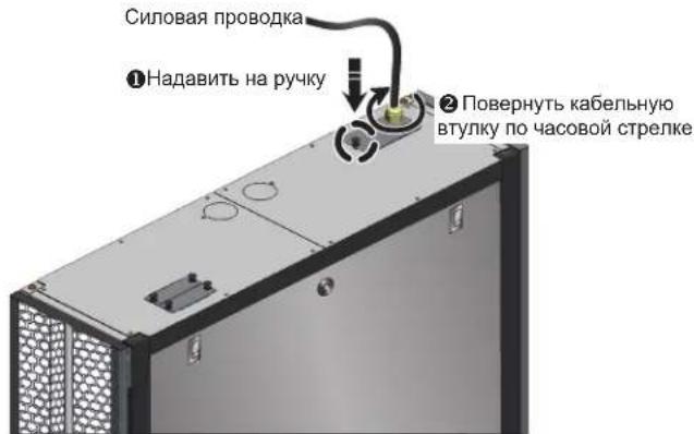
(Puc.3-15:YamaohokaHa Meo 3a2nyuKku KaebKaHana Cunoo np000 np000kU)
3.8.1 3neKtpoNTaHne
CnapenHbBxOa
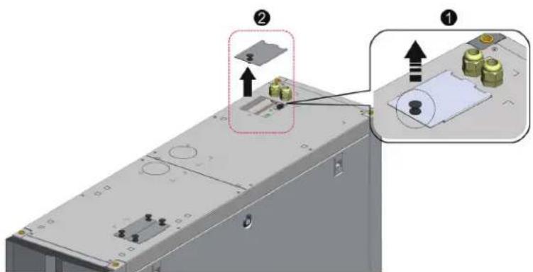
(Puc.3-16:Chamme 3aznyukKaabnb-kahan cunoeo npoeo0k)
3.YctaHOBKa
1 NToHHTe BBePx 3a pyKU H CHIMITE 3aRnykU Ka6b-kaHana IJaI CNIOB O npOBOKn 2 B 3aHeu qactn BepxHn NaHEn KOpNycA.
2 C nomouykyauek ydarnite BbHnBhle 3aIyukn1, oCTaHte DBe Kaebhble BTyKN H KOMNKeT A OCHaTKn, OTBePHrTaIKK KaebhBHX BTyNK 2, a 3aTeM C nOmoBIO Tnx rae npkpenute Kaebhble BTyKN K aynuke n npoTnHte CNOBnypnoBOnky ueep3 Kaebhble BTyNK 5.
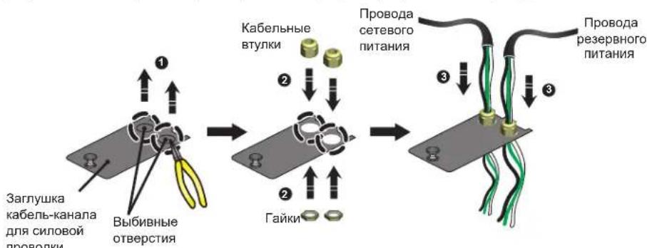
(PUC.3-17:Пбоьeончe сиоьоу npбоьdku)
3 MoTAn 3eNkTpnpOBOJKN yCpOCTBa SRCOOL60KCW BbInonHn Ha 3aBoJe-3rTOBHTEn H paccunHan nOIOKNOUeHne OOnHOHOr. C NOMOuio OTBePTKn CHMIMTe Dne nepembuHKn, coeHHHOueMeXdy cooBz 3aKMMb N1 u N3, aTaKxze 3aKMMb N2 u N4 (cm. PmC. 3-18 HXKe).
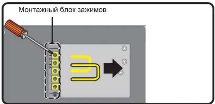
(Puc.3-18:Chmue 3a06dckux nepembuk)
4 C NOMOJIbIO OTBEPKIO OCNAb6Te BINTbI 6IOKA MOHTaXHbIX 3aXHMOB I C NOMOJIbIO KOJIbCeBbIX 3aXHMOB 3aKpENITE npBODa B 6IOKe.
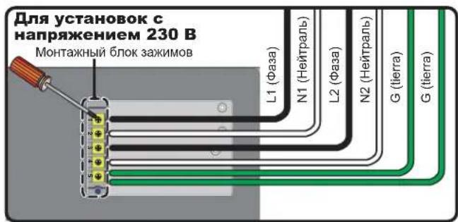
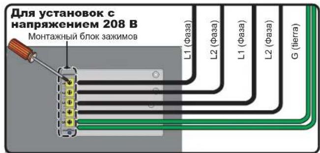
(Puc.3-19:MOnmaK cunobou npoBodku)
5 YcTahOBHTa Me cTe 3aRnykky Kaeb-kaHana CINOB npoBOKn H nnoTHO 3abePHTe KaebbHbE bTyNk.

(Puc.3-20:YcmaHOBKa Ha MeCmo 3a2znyuKu Ka6bEn-b-KaHaHa cunOoBn npOsOdu)
3.yCTaHOBKa
3.8.2 KondehcaatoBdoHa Tpy6ka
KoHHeCaTOOTBODHnA Tpy6Ka IIOOeDmHEHa K WtTyepy B HIXHeYacTn Kopnyca. DpyroEe KOHeu cIeNyET npOBcTn uepe3 CneuaNbHO ppeymTopeHoe dIa 3ToTOrO OTBePCTme B HIXKeH naHEnI dI CNbA KoHHeHCATA.
Hacoc dI OTKaKu KOHeCAta paccTuHa IPOknaKy Tpy6oNpOBOJOB K A B HnKHe (3aOBDCAKOMKnEKAua),TAKB BepXHe (cHcNoJIb3OBAHHeM PpOdaBaEMOrO tJeJIbHO KOMnEKA SRCOOL60KTP) cAchtn Kopnyca. Bcnyae BbOba BepXHe NOBDOx Tpy6oNpOBOJa Bbcota KOHeCAtonpOBOJa DnKHe COCTABnIe He 60nee 5 M.
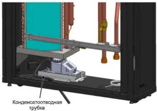
(Puc.3-27:YcmaHOBKa KOhDeHcAmoBmBDoHm py6ku)
3.8.3 bokynpabneHn
JIueBaCTopoHa

(Puc.3-22:Jueeaa smopoha 6noka ynpaeneuha)
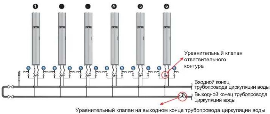
(PUC.4-6:BoDnBb6aannc)
Iporpamma npimmeHaet KOMneHcaunHb MeToN KoppeKtpye PaXoN, pinnHmraepBoe (Han60nee ydaeneHoe) ycTpoCTBO KOHNIOHNOHPoBaHn 3a onOpHyTOyck. Ipa daHHoro
npoecca Tpe6yTeC He MeHee Tpex OndOBpeMeHHO paOtaOxuX HcNoBek. Iprrpamma npimmeHaer KOMneHcaunHb MeToN KoppeKtpye PaXoN, pinnHmraepBoe (Han60nee ydaeneHoe)
ycTPOCTBO KOHNIOHPOBaHn 3a onOpHy TOyck. Ipa OcyueCTBNeHn DAHHOr npocceCa Tpe6yTeC NOMOuB He MeHee Tpex YcNoBek. Ipa NDepekaHn CB3M MEJy HMM peKoMeHdyTCR
HCNoB30BaTb NoptatNBhble yCtpoCTBA CBA3N. KOniueCTBO YcTpoCTB KOHNIOHPOBaHn B KOHType MoKet 6bItb pa3nnHbIM. Ipa BBIOHHeHn NOcneYIOUHX DeEChTBn B KaueCTBe Pnimepa
HCNoB3yeTcC XCTema Ns WectN YcTpoCTB.
1 YctaHOBHTe ypaBHnTeIbHbI BEHTNb Ha BOIOBbIyCkHOM KOHcI rnaBHorO TpyoBpObaI dIg KoprpeKTHPOBKN cyMMaPHorO paXOdaNo KOHTpy.
2 Cnmoouno naenynpnaBneHnpeBnTe BCE KOHNIOHOEPbI B pexm yCTaHOBKn (cm. pa3den 4.4 "Pa6oay TemepaTpyu BlaxHoctb"). Tpxxoobbie IapOBbie KnaNaHbI abTomatueckn OTkpBaIOTc HnOHy BeMunHy (100%).
3 PONHOCTbIO OTKPOME YPAHINTEBHBH BENTHb HA BOOBOYCKHM KOHc ME YPAHINTEBHBHBE BENTHb BO BEX OTBETHEHMA. 3aHHNTe 3HAeHnRA paXODa kaxdo yctpOCTBA.
4 Otperynpyte ypaBntelbHbBeHTnb BoBDbnyckHOro KOHa Ha 110% HommHaBHO rno nHoro paXOa. Ecny ypaBHeBbHbeHTnB He MoKet dOCTuB 3TOrO 3HaueHn npnnHOM OTKpBaBHnO, OCTabeE rO B NIOHOCTbO KTOBpITOM COCTORHN IN CKOPpeKTpye paxOd nponOpNOHaBHO dI KaKDo OTBeTBnEHn.
5 PONHOCTbO OTKPOIe YPABHTENbHbBEHTINbOTBETBNTEnbHOKoTHypaYCTpoIcTBa1.3aTEMOTPERyIpyTe ypaBHHTenbHbBEHTINb HAOBOBbIyCKHOM KOHcTnABHO Tpy60npoBOHO HOKoTHypa c TEM 406bl DaTb BO3MOXHOCTb YCTPOIcTBy 1OCTNcBcEOr HOMHANbHO 3HaEHMa paXoJa (±5%).Eue pa3 y6eHntecB TOM,TOero ypaBHHTENbHb BEHTINbOTBETBNTEnbHO KOnTHpA NOHOCTbO OTKpbIT.
4.Первонаальньл 3anyck
6 Otperynpyte ypaBHTbHnBEHTNb OTBeTbNTbHOro KOHTpya YcTPOCTBa 2 TaKIM O6p3OM, T06bH OH DOCTHM HOMHaHbHO 3aueHn paXOda. Ipyroen eNoBek 6ydtet HaobdTa 3a MmEHeHMe pacXoDa B YcTPOCTBE 1, DnHaMnueCKn peryHnPoBaTB ypaBHTbHn BEHTNb HA BOOBbyCkHom KOHe n KOMNEHCPOBaT b daBneHne BODt c TEM 406bI DaTb Bo3MoXHoCTb YcTPOCTBy 1 DoTHuB HOMHaHbHO r3aueHn paXoDa (±5%). Nocle KoppeTmPoBKn 3aunWite 3aueHne CTeneHn OTkpBtMy paBHTbHrO BeHTmN OTeBTbNTbHOro KOHTpya YcTPOCTBA 2.
7 Otperynpyte ypaBHnBnBEHnBb OTBeTbnteBHO KOTpya YcTPOCTBa 3 TAKM o6pazOM, Yo6bO OH DOCTH HOMHNHBOHO 3HAeHnPAxOda. Dpyro YenOBek 6ydt HABNOATb 3a N3MeHHeM PAcXoDa B YCTPOCTBe 1, INHMNHueCKn peryHnPoBaTb ypaBHnBnBn BEHnBb OTBeTbnteBHO KOHTpya YcTPOCTBa 1 IN KOMNEHCnPOBaTb daBHeHne BOBc CTem YTO6bI DaTb BO3MOxHOCTb YcTPOCTBy 1 DOCTuB HOMHNHBOHO 3HAeHn PAxOda (±5%). IocNe KoppeKTHPobKn 3aINNtte 3Haene HcTeEHN OTKpbITMa ypaBHnBHO BeHnBnOBHO KOHTpya YcTPOCTBa 3.
8 NobToPunTe 6 7 dA KoppekTNPOBKN YCTPOINCTB 4-6 H3aHnHTe 3HaueHne CTNEH N OTKpBTHN ypaBHTENbHbX KJNAHOB B OTBeTbNTenbHbX KOHTypax.
9 Pocne BbINONHeHn KOppeKTHpOBKn BCex yCTpoiCTB 3aNNWHTe 3HaueHn CTeneHn OTkpBTy ypaBHmTeJbHO rKnAnaHa Ha BOIOBbIpyCKHom KOHcN I NOHOrO paXoJa (HOMHaJIbHbI paXoJ ±10%).
10 B cnyuae HeBO3MOXHOCTNIOCTHXeHn HOMHaHbHOrO 3HaueHn NOHOro paXoJa IINBcero KOHTpya Nocne KoppeKTHpOBKn OTperyInpyte CKOpOCTb NtOKa BOdb, CO3DaBaEMORO oxnaIHeTeMe IM BOdHbIM HaCOCOM.
4.7 yctahOBka napametpoB IND-ynpabHeHn
13a pa3nHm B yC0BMAx OKpykaOcne Cpebl CEHTPOB 6pa6oTkn DaHHbXpeylnpOBKa 3auehen npametpo BN-ynpaBHeHn cenbdoocTHKeHMaKCMmaHBHO 0xnaJdEHN DOJIHkA pOn3BOMTBaCBAHnHnpuOBAHbIM cepBCHbIM nepcoHAm Noce yCTAHOBKn.
Pmuemueahe. Chaayana cneyem a3hakomumcbc unhphiopmauee 8 pa3dene 5.2"dykuuhoopaahue nane hnu npaaenhu" cuenboknnyumnb npcdmaeeHue o6 ochohm pekume paobmb.
Ipyb: Main Menu Setting Controller (TnabHoe MeHO HacrpoKa KOntrpOJIneP)

(Puc.4-7:Ycmanohokka 3HaQeHui NIM)
PnpopnoHaBbKaKoHCTaHTa (I)
BhOCHT KoppeKUIM MekJy N3MepeHHbIM 3HaueHemem TempeaTypbI N3aadHbIM 3HaueHemem TempeaTypbI.
5.3 3kpah cTaTycn rnaBHOe MeHIO
Supply Air
24.0°C 50%RH
Flow

Pn npexooycctpoiCTBA B COCTOHNIE 63dEChTBN K-DCINNEH N OHOBAA NOCBETKA OKNIOAOTCA. IIN B KIOUHOH FIOHOB NOCDBTKN H BBOJDAKPAH CTAyCA HAKMNT Ha KpAe CTATyCA OTbpaJAOCTC CTATYC NOaauu BO3dyxA N CKOPoCTb NOtKa BO3dyxa, CO3daBaEMO BENTHTAPAM (B PPOeHTAX OT MAKCNMAIbHO). PPOeHTHOE 3HAeHMe CkOPOCTB BO3duHOro NTOKA OTPaJaET CkOPOCTb BPAuenHE BENTHTIaTOPOB, uem BoJbwe CTOnbOu B07pApKaAETC B CPTKe CoTcHnM, TEM Bblwe CKOpOCTb BPAuenHE BENTHTIaTOPOB.
HaxoDbB EKpahe CStyca,HaXMMTE -DnBxOda B Main Menu ("TnaBHOe MHeO"),npEcdTabHeHoe HmKe.
B ciuyae Bo3HKnHOBeHn ABAPmHoro CnHnHa HxMnTe ▲, nocne yero Ha 3KpaH bSyet BbIeHdo pa3bcHene daHHoro CnHnla.
Power ON/OFF
Status
Setting
Administrator
Power ON/OFF (Tintanhe BKJI/BblKI)
3aynckyctpoiCTBA KOHNIOHOBAHINB(ABOTOMATWcckompekmE)IINBXOIBPEKIMOJXIDAHN.
Status (Cratyc)
IpoCmOp C0CTOAHH NCTeMbI, BpeMeHH paobToH JxypHana co6bItn.
Setting (Hacptpoika) (Tpe6yertcnapoIb nonb30baTea)
KopkeTINPOBka 3aAHHORO 3aueHMe, NOkAJIbHa HaCTPOMKa, HAcTPOKa KOHTPOnJIepa n HAcTPOKa ABAPINHO CMrHAnI3aUIM.
Administrator (AdmHnctpatop) (tpe6yetra napob admnncptapatopa)
BoiHte BpyHNOpeXHM DnI pnoCMOTpa BepCN npOwNBKN HAcTpoKNCMCTeMBI.
5.Зкплуатацья
5.4 NpObePka npaB doCTyna n BxOd B cnCTeMy
B CNTeMe ynpabHeHn yCTPcOB TBM KOHNIOOHPOBAHn HmEOTC DBe yETHe b3aNCH. YyETHa 3aNtcb aMHHCTpaTopa oecneMbAet MaKCMaJIbHbIe npBa N BO3MOXHOCTb I3MEHeHn BCeHacTpoE.KyETHa 3aNNCb NOnb3OBeTeNa dEt BO3MOXHOCTb I3MEHeHn ToIbKO CHTeMHbIX HAcTpoE.K
Input Password
0000
Pn nnonbTke BxOaB 3KpaH Setting (HacrpoKa) HIN Admnistrator (Admnnncptatop) noRBAeTc npednoJHHe BBeCTn napoB. Pm OTCyTCTBM KaKx-Im6 DeiCTBn NocE BxoDa B CNTeMy TekyuM CeaHc paobToB Hne npekpaaetc noCle nepeXoDa CHTeMb B COCTaHMe 6e3deHCTBn. Ia NoBTOphOro BXoDa BBIeYka3AHoe MeHIO HeoXoDMIO NOBTOPH BBECTn CBOI napOB.
PnBBOe npoA aMHHcTpaTopa B OKHe BBeEHNH npoA p3peWaeTcOcYueCTbN,IOCTyNHbIX aMHHcTpaTopy,a npn BBOe npoA noB30BaTeIa ToBko DeiCTBm,IOCTyNHbIX o6bUHbIM NOL3OBaTeIa. PnBxoDE ToBko B EKpAH Power ON/OFF (PiTaHne BKN/BblKn) mN Status (Ctaryc) BBD npoA He Tpe6yeTcA.
PapoiNb noB3OBATENo yMOJUaHNO:0000.
Ppmeue. Iy npoeompeauen Hecanuohupohnoo docmna u 3mehn baxhix hacpoek He coobuaime napb admuucmpamopa noamopnhum nuaam. Iy nonyuhen npona admuucmpamopa opauiimcck cepbuchoomy nepcoany.
5.5 Pa6ounepexmmbl
YCTPOICTBO KOHNIOHNOPBAAHE MMEET PABPEKHMOB paObTB:
PexHM pa6oTbOnncaHne
| Abtomatueckn perekim | Путб: Main Menu → Power ON/OFF → ON (Г lambове MENо > Питунente BKN/БblKN > BKN) Для обесчения КОНДИОHEРУ ВОЗМОЖСТСУВЕТСАВТOMATUWECKСО Упавлиени ССОЕ XОLOДОПОЛЗВODITIELСТБУВБЕРITE АВТOMATUWECKСК PEGKIM, в pezzлытate чero сизема abTOMATUWECKСК ПОИЗBEDEТ MИКРOKOPPERKEЦИКСКОPGСТВВВАПЕПЕВЕNTIVОПИСТЕНТERTРЕХODIBORO SHAPOBORO Клалань в COOTBETCTBUNС 3даданын� 3нчаленям. КрOME тORA, ддьбсгогу петерхлчеснma мжду abTOMATUWECKM PEGKIMOM U PEGKIMOM OZIMDAHNY Bы мочete odнOBPEMEHNO HAZKATB HA KONIKN ▲▼ И уderхквоть BX B TUCHЕНИЕТРЕССКД. Пюшевим.В ручим рекиме odнOBPEMEHNO HAZAMUE KONOK ▲u ux yedperkaime в мочевке 3 сухунда 3сухунда 3сухунда 3сухунда 3сухунда 3сухунда 3сухунда 3сухунда 3сухунда 3сухунда 3сухунда 3сухунда 3сухунда 3сухунда 3сухунда 3сух�п STANOMATUWECKS PEGKIM UNI PEGKIM OKIDAHNY. Perekim okizdahnia | Путб: Main Menu → Power ON/OFF → ON (Г lambове MENо > Питунente BKN/БblKN > OZIMDAHNE) В рекиме okizdahnia BEHTILATOPBY pa6o7aOKIHA MHNIMALBHO CKOPOCTN, TrpeXODOBOH SHAPOBOH KIANAPH NOLHOCTBU 3akpbIT, a oxlaJXDENHAR BOda пожддун'tchьо кOTHYPRTM, МИнуну змeeвик. Чужим рекиме ИСПЛБУETСД Ддя п罗веки Нормально рра6ытBu KMПОНЕТВ ИИОБЕСЕЧЕНОЕ рра6ытBu KMПОТДВЕТСД CpyuHbIMN насто рекиме РОБЗВATEЛВ BrpuchMuу YCTAHABINBAET CBpuchMuу YCTAHABINBAET CBpuchMuу YCTAHABINBAET CBpuchMuу YCTAHABINBAET CBpuchMuу YCTAHABINBAET CBpuchMuу YCTAHABINBAET CBpuchMuу YCTAHABINBAET CBpuchMuу YCTAHABINBAET CBpuchMuу YCTAHABINBAET CBpuchMuup WORNG ("BHMUMAHNE"), a 3yMMeR HeNpePBbHBO N3Дaet 3ByKOBbE CMHbALDДДITIELHOCTHBIO 0,5 cek Do bVbIXOДA N3 PEGKIMA UCTAHOBKN. Болей поpondуну ИнфоматICALO O p6o7aOKIHA MHNIMALBHO CKOPOCTB. Ппчелунда 4.4"Pa6ochay TempepaTyPru NlaxkhocT". |
| Perekim okizdahnia | Путб: Main Menu → Administrator → Manual Mode (Г lambове MENо > Аdmнисстар�р > Руно реким) Руно реким IMCПЛБУETСД Ддя п罗веки Нормально рра6ытBu KMПОНЕТВ ИИОБЕСЕЧЕНОЕ рра6ытBu KMПОТДВЕТСД CpyuHbIMN насто рекиме РОБЗВATEЛВ BrpuchMuу YCTAHABINBAET CBpuchMoу YCTAHABINBAET CBpuchMoу YCTAHABINBAET CBpuchMoу YCTAHABINBAET CBpuchMoу YCTAHABINBAET CBpuchMoу YCTAHABINBAET CBpuchMoу YCTAHABINBAET CBpuchMoу YCTAHABINBAET CBpuchMoу YCTAHABINBAET CBpuchMoу YCTAOKHOCTB. | |
| Pryно реким | Путб: Main Menu → Administrator → System → Installation (Г lambове MENо > Аdmнисстар�р > Uctanobka) Зотот реким IMCПЛБУETСД Ддя осUALHENIA Bo3dYxH MОрркгТROBKK BODHORO 6dANHca. Посlete erо задуcka ТрEXXXODOB SHAPOBOW KIANAPH NOLOCTBIO OTКPBbAETCSA, a BEHTILATOPBY BrpauHOTCS A MHNIMALBHO CKOPOCTB. Пппonaдану BINAJIKHOCSTB DДОПТДМь Pa6chIMДДANAOH HauHnaTe MHRaTb ИнДКaTOp WORNG ("BHMUMAHNE"), a 3yMMeR HeNpePBbHBO N3Дaet 3ByKOBbE CMHbALDДДITIELHOCTHBIO 0,5 cek Do bVbIXOДA N3 PEGKIMA UCTAHOBKN. Болей поpondуну ИнфоматICALO O p6o7aOKITALE TmpeNaTcType n BINAJIKHOCSTM. B pa3dJe 4.4"Pa6ochay TempepaTyPru NlaxkhocT". | |
| Pryннudтеловни реким | Путб: Main Menu → Setting → Controller (Г lambове MENо > Hab相对较ka > Korhtponner) ТрexxODOB WIAPOBOW KIANAPH NOLOCTBIO OTKPbIT, m BEHTILATOPBY pa6o7aOKIHA MAnKCMUMLBHO CKOPOCTN. Ддану реким, кak npabIMLO, Испльь ЗуETСДЯЯ Тсетирobань uCTPOCTB IRI BvlnonileHENH YA bApamHIOE OXANJXDENHIE. |
5.Зкплnyataцья
5.6 0TKIIOUeHne
Ipyb: Main Menu Power ON/ OFF Standby(TnabHoe MeHIO > NHTaHMe BKN/BblKl > OxuHaHne)
System Mode
ON Standby
Sure? Y/N

BHUMAHVE!
B pexnme oKnadHn yctpoCTBO npdoNkaeT haoDntbC noH anpnaKeHem nHTaHn! Ira nonHoro oecToHbAHHy yctpoCTBa B peKnme OKnadHn Heo6xOdmoOTKnIOHTb erO t HcTOHnKA BxOHDHO nHTaHn.
IgnoOTKJHueHnKoHdunOhepa Chayana neepuDte B pexMM OxmdAHH. Iocne bbybopa pexHMA OxMDAHHBbEpTeY (DA), a3aTm HaxMMTE 1nnaonTBepHdEHH. Ecm BBcBueHbAETC INHdkATOP STANDBY, 3TO CBDEtncbCTBY T OTM, 4TO yCTpOHCTBO HAXDUTCB B pexMME OXMDAHN. Pn3TOM KOHdUnOHeP IpOOnKaET HAXDHTCB B 3aNTAHHom COCTORHH, aero BEHTMIATOpbl BpaauTcC MHHMaJIbHoH CKoPOCTbO.
3aTeM 0TcOeHNHTe BHeHIN NtOCHN KITAHNA. Y6eHNTecb B TOM, YTO BEHTNIATOpbl OCTAHOBINHC, a KK-DnCnneo TKNIOUYNCA.
5.7 HacrpoiKoHnDnOhepa
5.7.1 YctaHOBneHoe 3NaueHne
Ipyb:Main Menu Setting Set point (TnaBHOe MeHIO> HacrpoiKa >YcTaHOBnEHoe 3aHaene)
Supply Air T: 25^ C
Spply Air T (TemnepaTpa noidabaemoro Bo3dyxa)
B ATOMaTneckOM pexIMe yCTPOHCTBO KOHNIOHOHPoBAHNA ABToMaTHueCKn peYnpyet paB0Ty BeHTINrTOpOB IN TpExxOBoI OAPoBOI KlaNaHa B COOTBeCTBM C cytTaHOBneHHbIM 3NaHeHMe TEMpePaTybl PnDABAEMOr BO3dyxa.
5.7.2 JokalbHa HaCtpoKa
Ipyb:Main Menu Setting Local Setting(IbaHoe MeHo HacroKa IokaBnaH aHaCroPaKa)
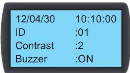

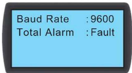
CCTeMHoeBpeMa
YCTAHOBHTCnCTeMHoeBpeMaCNMOoJIbKHOIOK ▲;ДЯпepexOaВcneуOоe noneHaKMITE TaemHaKMITE nAbePxDeHnA.
HHTnKATop (homep)
PepctabnHcobH oHemop nocneobatbno noKlnquenHOrO yTpoCTBa KOHNIOHOBaHnA a taKe uJeHTmKnaIOnHOe 063HaueHHe B npToKone Modbus. IyoMouaHIO yctahOBnH Omep 1. PnncnoeobatbHom noKnKlueyHn HeckonkbHX yTpoCTB KOHNIOHOBaHn Hoe6xoIdmo npCBOITb kaxdMy yTpoCTBy otnnHHb ot dpyrHex Homep.
5.Зкпnyataцья
KoHTpactHOCTb
06ecneuBaet perynpOy KOHTpactHO tKpaHa dKnner (0~5).Ito ymOnaHIno yctaHObHeNo 3aHuEHe 2.
YcTPOINCTBO 3BYKOBOI CNHAIIN3aUNI (3yMMep)
06ecneuBaet BKIOHueHHe/OTKIOUeHHe 3BkyBOO CmHAnI3aunn N Opaay 3ByKOBOrO CnHana IIN HANOMHANN NOb3OBATEJIO O IO6bIX CO6bIMAX, pMBOAUX K cpa6aTbIBAHNO abapnnHO CnHAnI3aun. No ymuaHnO yCTAHOBNeHO nolooHHe ON (BKJI).
3bIK
YcTahOBITE A3bIK OTO6paXeHINHOpMaUIM. BbIbePte A3bIK NAKMUTE -nIy NOITBeKJEnH.No yMOUaHIO YCTAHOBEN aHrnnckm 3bIK (EN).
PpObn nObn30BaTeIa
IaIyI3MeHnHa TcKyuJero npoJIa NOnb3ObaTeNBAVeBdmeTceYbIe U
EHHHuaN3MeHeHHN
yctahabnbaet ednHmuy 3MepenHr TmempeaTpyb. Iyo mJuaHnO yctahOBHeNo (^)
BnIOUeHne3aIepKKn
Ioka3bIaBET BpeMeHHO HHTepBaM MeJy yCTAHOBKO 3aYcKa BA BAtOMaTHueCKOM peKIMe H aKTmueCKM hauJOM paObTy yCTPOCTBA. KOHNIOHeP 3aYcKaETC qpe3 3aDaHHbINoJIb30BaTeEN pnoMeKyTOK BpeMeH N CekyHdax.
OkoopocTb nepeaH daHHbIX
YctahabnBaetckopocIpepaHmHOpMaunB CETM NO npToKoJy Modbus.Bo3moXhBcBepaHbTb:9600,19200,38400N57600.NoymuHaHIOyCTaHOHeNo 3aueHne 9600.
0a aBapnna CnHaIm3aun
YctahabnBaetto,Kakoeco6bItneMoKTe npBodntbKcpa6bTaBbAHnOynpabnHooeryxoroKTOKTA1.MeETcBA BwDy cneDuoyooee:
- All (Bce): B 30m cnyae ero cpa6abTbBAHHe MOXeT 6bTB bB3BaHO NIO6bIM CO6bTIeM, PIPBODAIUM K NOaJe abAPHIHO CHHaHn3aUM, HIN OTKa3OM.
- Fault (OTk3):ero cpa6aTbIbAHHe MOXET 6bITb BbI3BaHO TOnBko OTKa3AMH
Co6bTn, npBDOJxue K noaue aBapHNoH cnHaHn3aun
1.3acopeneHne HnbltpoB 5.BbOkaa/HmKkAckCkoPcbNtOKa oxnaJeHHoBdo
- BbICOKaH/HN3KaTe TMnepaTypa/BNaJXHOCTb, fHKcnpyMaJ DnCTaHUNHHbIMN daTtIKaMM
2.HappyWeHHe HOpMaJIbHorO nopRAkA BHyTpErHrero B3AMoDeIcTBn
-
Правлиейные ведименоги Исторьа Тхшемпеского 66сужимаваян.
-
BbOcKaH/HmKaTemNepaTyPbBnAkhNoCTb NpOaBaEmoro/OpTaBoTaHHo Bo3Dyxa
- BbocKa/Hn3KaTeMtnpeTaPtyoXnJaDeHNoB0DyHaBxOe/BbxOe
0Tka3bl
- AbapmHbOCTAHOB / dIcTahmOHbH bApmHbO octAHOB 7. BixoJ noka3aHn dIcTahmOHoro DaTHMka 3a npedbl HOpMbI
2.ПереловkoнданcaTа
8.BbIXoI nok3aHn DaTtNka TeMnepaTypl oxnaJdeHHo B0bl Ha BXOe/BbxOe 3a npdeBbl HopMbI
3.Cpa6aTaBbAHHe abapHnHOro CnHana yTeKN/abapHnHOro CnHana pa3MbkaHnna 1NeKTPueckcOuEN BpeyNbTate yTeKN
-
BixoN nok3aHn paXoJOMepa oxIaXeHHO BoIb 3a npedeJIb HOpMbI
-
Bo3ropaHne 10.HappyHne HOpMaBHO npabTo bEHTnTTopo
- 3aBIMHeH 11.HapuHHeH HopMaHbHOpa60tbpTeXxOBoTO WapOBOrKnAnaHa
- BixoJn kokaHnn daTnka TeMnpaTybI n BlaxHoCTn noDaBaemoro/oTpa60TaHHOR BO3dyxa 3a npedeBbl HopMbI
5.Зкпл�атуня
5.7.3 Hacpoika KOnTpOJIpepa
Ipyb: Main Menu Setting Controller (TnabHoe MeHIO HAcTpoJa > KOnTpOJIneP)


PnHyDnteHbHbpeXHM
PnBkHouHeHH npHyDntbHoro peKIMa BeHTNAtopbHaunHaOTo pa0TaTb Ha MAcKmAlhHO CKOpCTn, a TpeXooBOoI uApOBo KlaanH noHocTBIO OTKpbBaetc. PpHpynteHbH bpeKMM, KaPpABINO, HcNtB3yETc dnn pOBepKn EcknpyaTuOnHHbx XapAKeTpHeTMc Nnn pRn BbcOKo TeNtboH Harpy3e.
MnraHne HnndkaTopa STANDBY Ha naneHn ynpabHeHn CBnTeBnCTByeTo TOM, 0y YcTpoCTBO p6oTaet B npHnHyntbHm peKHe. YctaHOte nponopmoHaIbHyIO n npom3BOHyIO KOHTaTbI (napaMeTpbl NID-ynpaBHeHn). CM. pa3Je4.7 "YctahOBKa napaMetpob PND-ynpaBHeHn".
Mn Flow T (MHHmAbha TempepaTpa NoToKa)
Pn naeHm TemepaTyb Otpabotahoro B03dyxa Hxke daHHoro 3hauehn BEHTNlTopb HaMHaOT pa6oTa bHa MMHMmaBHO CKOPCTB U cienax KOHOMM 3neKTPo3HePM. 3haueHne no ymonuHmo:25°C (77°F).
Max Flow T (MaKcHMaNbHa TaMeNepaTpa NoToKa)
PnnoBbIeHmTeMnepaTpybOtpa6oTaHNO Bo3Dyxa Hxke DaHHoro 3HaHHeN BcHTmApToBpaHauHaHO Tp6oTaB Ha MaKcMaMbHOckOpocTH. 3HaueHHeNo yMOuHAnIO: 40^ (104°F).
Fan Step (ctyneHb BENTnIaTOPOB)
YCTaHaBnBaetCKOpOCTb BpaueHnBEHTmIaTOPOB (DnaHaa3OH:0~15) BA tOMaTHueckOM pexHM. IIO yMOuaHIO yCTaHOHe 3NaueHMe 0, IN KOHNuHep perympyET cKopoctb BpaueHn BEHTmIaTOPOB 3aBHCIMoCTN 03daHnhX Nl630BaTeENeM yCTaHOBOK.
Anto Recover (abTomatueckoe BocCTaHOBNEHne)
Ecn daHnayHKnBkNoeHa, a CNTema nepeoTknOueHem nTuHnPa 60tae TB ABtOMaWcckom pexnme, To noCne NOBTOPOrO 3anycka yCTpOCTBO cpa3y B03bpaauaetcBA bTOMaTNeCKn peKMM.
Intelligent (MnKpnpoueccoppoeynpaBHeHne)
Ioka3bBAe, 3aedCTBOBAAHn yfHKUNMkPONPOeCCOPHOynpAbeHNA. DAnHn OOnu TOnbKO OToObpaaet aKtueckoe COCTOHHe; N3MeHHeNdeHHo HAcTPOmK NOJIb30BaTeHE MeBO3MOXHO. INr N3MeHHeHNAcTpoek CM.n.5.7.10 "HaCToPAKeHMA abTomTueeCKoro ynpAbeHna".
Leak Cut-Off (otKIOUeHne npu yTeueKe)
Ecn daHna hyKun BkJoueHa,To yCTPOBCTBO aTOMaTHueCKN OTKJIOAeTcPn O6hApyKeHH yTeKu BOdi.
5.7.4 Hactpokka cnHnHaI3aIu
IyTB:Main Menu Setting Set Alarm(TnabHoe MeHIO > HacTPOKa > YCTaHOBKa CHTAHIN3aUN)
Sensor Alarm
Actuator Alarm
Out of Range
06ecneuBaet yCTAHOBky CnHnHa3aun OTKa3a DaTcNKB, CMHaIImaun OTKa3a PmBODa N CnHnHa3aun BbXoDa npaMeTpo 3a npeJebl yCTaHOBHeHoro Dma3oHa. Ecn HnpoTIN KaKoro-Imo 3JemeHTA OTObpaKaetCaTo daHHb IeMeHT OTKnOueH. HaxoJaCb B Noone daHHoro 3JemeHTa, HaxMTe , Bem C nomOsbKOHNOK ▲▼ BBbepTe N HaxMMTE
Pumuehue. B cyuae 03nHOBENH KAKO2o-nu6 cobimua, b13b1aoue2o cpabmbahue abapuiHou cuZanlauu, npu paBome e pyHOM pekime u hdukamop u 3yMMep He kKIOAHOMc, Ho camo coBmu fukupemyem a xynpHane cobimui.
5.Зкплуataцья
Sensor Alarm (cHrannn3aun oTKa3a daTnikov)
IyTB: Main Menu Setting Set Alarm Sensor Alarm (ΓλaBHeo MEno HAcTPOKa YcTaHOBKa CmHaJIIm3aMn CmHaJIIm3aMn oTKa3a DaTHKOB)


YctaHbnaBt npabnBA BkIOueHr/OKIOueHr CmHaN3aUNI DaTUnKa napameTPOB OTPoTaHoro Bo3Dyxa, daTUnKa napameTPOB noDaBaemoro Bo3Dyxa, DuctaHcHbIX DaTUnKB 1-4, DaTUnKa napameTPOB BObHa BXOe/BoixOe, pacxoOpomea H Leak SEN (YbCTBntBHeOCTbeTeKTopa yTeKN).
Aetuator Alarm (CnHannnaaun oTKa3 npNbOda)
Ipyb:Main Menu Setting Set Alarm Actuator (TnaBHOe MeH0 > HcToPoiKa > YctaHOBKa CnHaJIIN3aunm > PpNbOd)


YCTAHABINBAET npabWn BKNIOHEN/OTKIOHENM CnHaN3aUNI INI Wapoboro Klanana N BeHTnAToPob 1~8.
Out-of-Range Alarm (cHannn3aunB bixOda npametpo 3 npedeIy cTahOBHeHHoro dna30Ha)
Ipyb: Main Menu Setting Set Alarm Sensor Alarm (TnaBHe MeHIO > HactpoKa > YctahOBKa CnHaHMaazuN > CnHaHMaazuaa BbIXoJa npaMeTpob 3a npedeBly yctahOBneHHoro dnaana0ha)
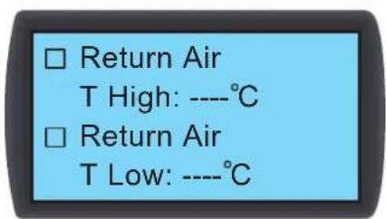

5.7.5 Npocmotp cTaTycacnCTembl
Ipyb:Main Menu Status System (TnabHoe meHo > CtaTyc > CncreMa)

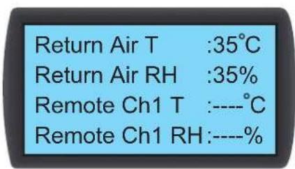

OpMpyet 3aIpOcBb OTOHHeHHHOpMaun, CB3aHHO CnCTeMoH, BKNIOA OXnaJauOyIO CnOC6HoCTb, Tempeatpyu BnaXhoCTb NODaBaemrO Bo3Dyxa, Temepatpyu BnaXhoCTb BO3Dyxa B MceT yCTAHOBKn DnCTaHUNHO rO DaTHK2, Temepatpyo BO3Dyxa B MceT yCTAHOBKn DnCTaHUNHO rO DaTHK3, Temepatpyo BO3Dyxa B MceT yCTAHOBKn DnCTaHUNHO rO DaTHK4, Temepatpyo OXnaJauEHNBOdyHa BxOJe/BbxOJe, paXoJ OXnaJauEHNBOdy, CTENb OTKpbITN WApOBOrO Klanana, KOMaHdb b OTHoWeHH WapOBoro Klanana (yCTAHOBKa CTeNEHOTKpbITN WApOBoro Klanana), KOMaHdb b OTHoWeHH WapOBoro Klanana), 3aJeCTBOBAHne FyHKU E.P.O., 3aJeCTBOBAHne NoXapHO mCrtan3aUn, 3aJeCTBOBAHne DmBoOIB CNrHann3aUn, OKa3 fNtPob, 3aONHeHne NOdoA nC6pa KOHehata, 3aJeCTBOBAHne KOHTpony TeYek (BkNoHeNe DETeKtopa YteKIN BObl) npa3MbKAHne 3eKtpueckoi cien npn yteke (npobEmbl, CB3aHbIe Cp a3MbKAHMe/KopOTKIM 3aMbKAHMe 3eKTPueckoi cien npn cpabTaBAAH NDETeKtopa YteKIN BObl).
5.3Kcnnnyatazaia
5.7.6 NpocMoTp /c6poc HhOpMaun O BpeMeH pa60TbI
Ipyb:Main Menu Status Run Hours (TnaBHOe MeHIO > CtAtyc > Bpempa60tb)
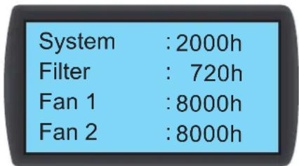

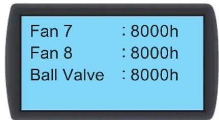
Opmpyet 3aPocbI B OTHoWeHHn CHTeMb I KOMNoHEHToB UcTpoCTBa DnA CoDcEChTBn B OcHKe COCTOB N KOMNoHEtOB N Ha3HaueHn BPemHeN IN pMeHOHTa Mm 3aMeHbI.
5.7.7 IpoCmToP/ouNCTka JyPhana co6bItn
Ipyb: Main Menu Status Event Log (Tnabhoe meHIO > CtaTyC > Kyphan co6bTuM)
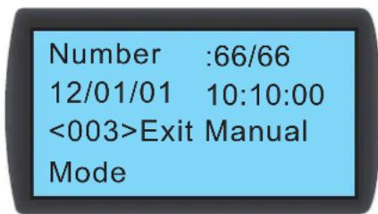
Ha 3OM kpahe oTo6paKaTa cKoNueCTBO TcKuHx Co6bTm / 06eue KOnueCTBO Co6bTm. Bcero MoKeT b6bTb 3aKcnpoBaHO 3000 co6bTm. IJIpeKIOUeHMeJy Co6bTmMn HAKMTte ▲▼. Hymepaunca Co6bTm pOIN3BODnTc COrnaCHO BpemEH Nx PPOCNXQENHe. YEm CTapee Co6bTme, TEM MeHbIe ero npAikOBbH Homep. Uqphpa, yka3aHnB A<> yka3bBAet KOD co6bTm. Ecln KOnueCTBO 3anCe npeBbHaer 3000, To HObIe Co6bTm 3aNcBbAOTC NOEpx cambx CTapbx.
Дя ouchтkn li6o ro xyphana co6bHn trpe6yetra napOB aamHHctpaTopa. Nytb: Main Menu Administrator System Clear Log (TnaBHOe MeHIO > AamHHcTpapop > Cntema > Ouchtmbxyphan).
Ppumueh. Kpyhan co6bmu npceomcmaenco baohyu hnpopmauon daouekencu cunemmba knae cnpaohn maepua nra cepbucho nepoana npu ocyeene mexnueckoo 0cbnyuabaun. Ptoommy He cdeym npou380db oucmy jyphana co6bmu be3 paeeuenu.
5.7.8 N3MeHeHne Tnna CnCTembl
Ipyb: Main Menu Administrator System Type (TnaBHeo MeHIO > AdmHHnCTpaTop > Cntema > TnI)

OTcIeKbAETB3aMmHOe paONIOKeHHe XoOJHbIX/roPaxn npoxoOB B cHTpe o6pa0TK DaHHbIX Dn BbIPOINHEHNA HCTPOIKN CNTEmbl: OPEN (OTKpBITO) IIN CLOSED (3AKPbIOT).
5.Зкплуатацья
5.7.9 BocctanOBJIeHne HAcTpoE no yMonuHaHIO
Ipyb: Main Menu Administrator System Factory Setting (Главhoe Меню > Адminнсразtop > Систema > 3авордкне Настpoик)
Factory Setting
Reset Component
Set Run Hours Time
1100h
BocctaHabnBaet Bce 3aOBCKeHa cTpoKm, BKIOUaY aYCTAOHBeHHbIe OIcIMn I npoIM nIb3oBeTJIa N adMMNHTcpTaTopa.
Ipyb dnc6pca BpeMeH pa60bTa TOrO Hm HmHO KOMnoHEna BblrAaT CnDyUoWM 6pa3om: Main Menu Administrator System Reset Component (TnaBHe MeHo> AdmmHCTpaTop > Cntema > C6pc BpeMeH pa60bTa KOMnoHEna).
TIOe 3aMeHb TOrO INI HHO KOMNoHEHa CnEyET POnB3BeCm C6Pc BpeMeHH pa60tB fHbTpa, BeHTnAToPob 1-8 I WapOBoro KNAnaHa.
System
Filter
Fan 1
Fan 2
Sure?

BHUMAHVE!
PnBocCTaHOBLeHn 3aOBCHX HAcTpoek npOnCXoDIT C6poc paHee N3MeHEnbIX HAcTpoek nn NapametpoB! YcPoietBO KOHNIOHPOBaHne BbnpaET p3NHyHe HAcTpoKn B 3aBNCMOCTn OT p3NHyHbIX CpeJ. BocCTaHOBLeHne npOn3BOhO yCTaHOBLeHbIX HAcTpoek MoKeT PnBecnK CNTEmHO OwH6Ke. BocCTaHOBLeHne ChTeMHBx HAcTpoek DoJXHO npOn3BOHTbcr TOnbKO KBAHNOHpOBAHHIM CepBNCbIM NepcoHaIOM.
5.7.10 HactpoJa paexima aBToMaTHueckoro ynpaBHeHnA
IyTB: Main Menu Administrator System Intelligent (TnabHoe MeHo >AdmHnHcTpop>MMKpOpoceccOpHoe ynpaBHeHne)
Intelligent : OFF
DaHnoe yCTPOIcTBo NOdEpeKHNBaET DBA TnA peKHNMOB ABOtMaTHuCeCKOrO npaBHeHHN:
1. Intelligent control (MnKpOpuoccpOpoe npaBHeHne) (noymoJauHIO)
CnTeMa aBToMaTHueckn peyHnpyeT pa6O Ty BENTINaTOpOB IN PnBOIDA B COOTBETCTBn C yTaHOBHeHHbIM 3HaueHMe TEmNepaTypbNoIaBaMoTO Bo3Dyxa.
2. PID control (ПИД-унравлике)
CnTeMa npOn3BODNT KOppeKtIpOBK B 3aBcHmOCTN O T3NaueHnI NpApMeTPOB PINД-упаВлeнWA.
Pn nepexode yctpoCTBa B ABOTAMTHUeCKn peKm HAcTPOHKO no ymoJauHIO ABJIaTeC MKNpOPOeCCOPHO ynpabHeHc. EcnpeKmMMKnpOPOeCCOPHO ynpabHeHc,TO CTema ABOTAMTHUeCKn pumHeHrE pKmM NID-ynpaBHeHn. Iyra BkIouHeHr/OtKIOueHn peKMa MKNpOPOeCCOPHO ynpabHeHr Tpe6yeTc npoB aDMNHCTpatopA.
6. Habtroponka Be6/SNMP-npoToKoJIOB
6.1 Hactpoika npotoKoJa SNMP
CcyecBytHTeckOJIbKcNOco6OBHAcTpoKNBe6/SNMP-KapTbI:
- Be6-nHTepfeic: nHTepfeic TLNET Supervisor oecneuBaet BCEoBemIouee ynpaBnHne cHcTeMoN KOHTpOb 3a ee npaMeTpAm. Boone noDpo6Hyo HΦopMaunCM. Bpa3dene 6.1.1 "HaCtpoJa Be6-nHTepfeica".
TLNET (System) Configurator:ДябсгюнсргдьБe6/SNMP-карычep3сетьнспьуITEdoctунудяСациваняпогрмmy TLNET Configurator. Gonee noDpOHyu INHΦopMaHIO CM.В раддene 6.1.2 Hactpoka cnncnblzOBaHnem TLNET Configurator.
Pekm Telnet: Hacpoka Be6/SNMP-KapbTb Chee3 CeTb B TeKCTOBOM pekm.Bolee NoDpOHyuHnFOpMaunCm.B pa3dene 6.1.3 "HaCPOka c nomooBto Telnet".
COM-nopT: npn OTCYCTBmC cTeBOrO coeHHeHnHaCtpoKa Be6/SNMP-KapbI MoKet 6bItb npOn3BeDeHa Chepe3 ee COM-nopT. Boone noDpO6HyIO HfOpMaUHO CM. B pa3dene 6.1.4 "HAcToPka YcePe3 COM-nopT.
Ipumeeuua:
Ipu npboonauhno nokmouuee K cemu 66/SNMP-kapma nbmaemcrnnyumb IP-adpec no npomokony DHCP. Ecn npomokon DHCP b dahnou cemu he uonnbymcra, mo docmyn K be6/SNMP-kapme mokem ocyuecembamcbc uonnbobaoaeh em IP-adpeca no ymonuho: 192.168.1.100
-Дя obecneueHna beonacochmu cuminbHn hcmormebnho pekomehyemc mehumbepzucmpauOHoe Uma noh3oamena u napno b noce nep8o2o axoda a cuimemy.
6. Habroka Be6/SNMP-npoToKoJIOB
6.1.1 Hactpoika c nOmoosbko Be6-nHTepoeca
Дан haсторки сnteMbI uepe3 Be6-6pay3ep cIeIyIte npmbedeHbIM Hnke yKa3aHnM:
192.168.1.100B aipceHyio ctpky.
War 2. Boi nte B cmtemy kak aDMHnCTpaTOp (MMA NIOB3OBaTeRn/napoNb NO yMOJUHaHMo: admin/password, cyHTom prrntpa).
War 3. HaxMMTe System Administration User Manager (CnCTema > ADMNHCTPNPOBAHne > Dnncetep nonb3oBATEe) dna yctahOBEnHnnoB3oBATEnbcknx mennapone B pa3ene "Local Authentication" ("Kokanbha ayTeHTNfKaAua"). Dnpa p3aunhbx kateropn nnonb3oBATEen npdeycmTpBaIcTc cneyuune npaba doctyna:
1)AdMNnCTpaTOp:ynoHNOMoUeH MeHTb IIObIe HAcTpoiKn.
2) DnneTpepyctpoBt: yonHOMOHMeHaTb HaCTpOaKN, CBa3aHHbIe CytPoiCTBaAMN.
3) NpIb3OBaTeN b cOCTynOM yPOBnRAe-Only ("TOnbKO TcHHeN":yONHOHMOueH ToBko nPoCMaTPBaTbHaCtpoKn.
YaknHe BpyHy, pa3peWaaetcI IIN noB3OBaTeIaM BXoD BCHTeMy I3 DpyTmX NOKaIbNbIX CteT. Ipi Heo6xoIMocTH 6NoKpOBAHn NObIbTK BxOda BCHTeMy Uepe3 BHeuHne nOdknueHHy Bbl6epTe onuHIO Only in This LAN ("ToBko 3Ta JBC"). B npOTbHM cNyuae Bbl6epTe onuHIO Allow Any ("Pa3peWntb H3 NIO60")
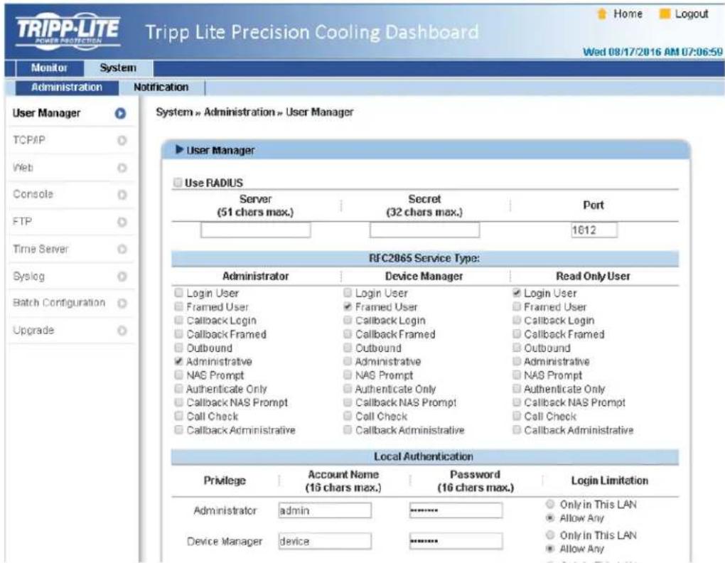
War 4. Haxmte System Administration TCP/IP (CnCTema >AaMMHcTpObaHne TCP/IP) nna 3aHaHn MHeHxOCT-y3na, IP-aDpeca, MaCKn noCetn IP uH03a dna Be6/ SNMP-Kapbl.
War 5: Haxmte Time Server("CepBep Bpemn") Iy yctahOBKn CNTeMHOro BpeMeH N daTb BYPCHIO NIO OecneueHn BO3MOXHOCTN ABTOATMueckOHNXPONH3aUMBpeMeH MEXdy Be6/SNP-KapToi N cepBepamn BpeMeH.
Ppumuehne. Pnna hnpoeypa hacmpoikee6/SNMP-kapmb npdecmaenepa3ene 7. Pp0pa Mma Precision Cooling Dashboard
6. Habtroponka Be6/SNMP-npoToKoJIOB
6.1.2 Hactpoika c nomoublio TLNET (System) Configurator
DcTnHraI KauHbAHy TmHHTa TLNET Configurator (coBmeTUMAR OC Windows 2000/2003/2008/XP/Vista/7) oecneuBaET BO3MOXHOCTb IeKo HAcTPOK SNMP-3JeMeHOB CNTeMbI O6HOBNEHMy IN POnuMKn. BblonHITe pnpBeDeHhble Hnke yKa3AHN:
War 1: C nomoosbu Ka6ena Cat5 noKknoHTe Be6/SNMP-kaTpy ue3 ee cTeBOH npT K cTeM.
War 2. Y6eHntecb TOM, yTO DBA DIP-NepeKIOUOATEN Be6/SNPK-KapTbY cTaHOBNEHb B NOIOKeHne OFF (HOpMaIbHbI peXMM) dIN oBeCneHnBa3MOXHOCTN nepeaun daHHbx nO cetu nTO paBOOaA CTANZM N UcPOIHCTBO SRC0OL60KCW HaxoJATCR B OHOH N TOH Jx NOKaIBHO CETN.
War 3. Поссе сашевая заустe Configurator.
War 4: HauMte Discover ("HaiT") dIa no hcka BceX doctynhbx SNMP-ycptnoCTB daHHO noKaJbHO cTeH. CmKo o6hApyeKeHHbX yCtpoCTB BBBOIDTC Ha eKpaH.
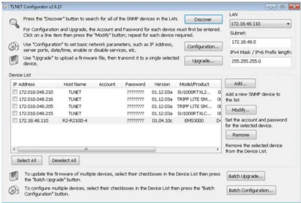
IpumeauHua:
Ja nou cka SNMP-ycmpoicmb a kakom-nu 60 dpyzom domene uzmehume noodeb (Subnet) u dnuhy npefukca Ipv4/Ipv6 u haKumme Discover ("Hoimu").
- EcnBnE6/SNMP-kapma He haoobum, npoBepbme, ymo6b UDP-nopm 3456 paboei cmanu u6bn omkpbim.
War 5. Bb6epnty yctpoiCTBO SRC0OL60KCW, npametpykToPOnpOto npednonaraTcN3MeHnTB, n3 cncka yctpoiCTB (Device List). HaxMITE Modify ("N3MeHnTB") N BBeDHTe IMAI nonb0BaTeRn npoBn aAMNHnCTpaTopa (no yMOUAnHm: admin/password, cyETOM perNTcpa).
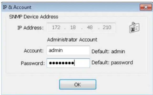
6. Habroka Be6/SNMP-npoToKoJIOB
War 6. HaxMMTe Configuration ("KonHpyaun")ДЯнЗМЕнEHcTeBbIX HAcTpoEK.
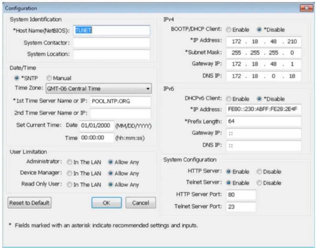
6.1.3 Hactpoika c nomoubo Telnet
War 1: C nmoio bocetoboro kabena Cat5 noiknoume Beb/5NMP-kapry uepe3 ecebeo npot K cetm.
War 2. Пдклочаразбουчу санцин (conepaunhoнссгетemon Windows nlinx) к тонокальон сети, к кторpoiodknquoehy ctpoctBO SRCOOL60KCW.
War 3. Pn mCnoB3OBAHm OnepaunHOH CNTeMb WiNds 3anyCTHe pexMM KOMaHNO CTPOK DOS (Start (Iyck) Run (BbInonHtB) BBeHnTe c KJIaBnATpyb I cmd HAKMITE Enter). Pn mCnoB3OBAHm OnepaunHOH CNTeMb I iXus 3anyCTMe Shell.
War 4. BBeHne telenet < IP-aPec > yIy cTaHOBHeHn telnet-coeMHHeHc BBe/SNMP-KapToH.
War 5. Nocy yctahOBHeHMA CoeHHeHNA BBeHnpe pntpaunHO He Hn npoIb adMaHHCTpato (no ymonuHa: admin/password, cyetom pernctpa). Ha kpahe noBlaTcra rnaBHO MeHIO. Bonee noDpo6HyIO INFOPMAUcM. B pa3Je6.1.5 HactpoKa B TeKtOBoM peKHM
IpumeyauHua:
- Be6/SNMP-kopma npepbbaem coedunene npu omymcmtu du cmtu 6 meuehe 60 cekynd.
-Плобая поцедураимрайки рпсдмбенийа в раздene 7. Позразма М precision Cooling Dashboard
6. HabtpoIka Be6/SNMP-npoToKoIob
6.1.4 Hactpoika chepe3 COM-nopT
PnO tCYTBm CTeBOro CoeHHeHnHa cHtpoKa CnCTbMy Koot 6bIb np03BeDeHa Chepe3 ee COM-nOpT. BbInOnHte npBedeHhbe Hxke yka3aHn
PumueeHne. Ppu pa6o me cakoiu nopeauouho ucmemoo, omnuohm om Windows, cm. kazanua no pa6ome Telnet-Knuehmmu, u3noenbte ypko6odcme nonb3o8amenn cceu cumem.
War 1. C n o m o u b l y n o c t a b l e m o r o B k o m p l e k e t K a b e n i c p a s b e m a m R J45 n DB9 c o e d h n t h e C O M-n o p T y c t p o i n c h T B S R C O O L60K C W C C O M-n o p T o m p a b o c h e n t a h u n i n
War 2.y6eHNTecbBTOM, yTO DBA DIP- nepeKnIOaTeNa yCTaHOBneHb B noLoXeHeNcE OFF (Bblk) (HpMaIbHbI pexMM).
War 3. Пи Кплбов�ьн Oпацьнгс РСТЕмы Windows 2000, 2003, 2008 XP Нжмite Start Programs Accessories Communications (Пуск > Погаммы > Тандартны > CB3b) И Вьберпс орю HyperTerminal.
Pumeyane. Onuhy HyperTerinal yanaenakomnue Microsoft 1s onepaonohx cucmem Windows Vista u nopeyouux epcui. Ipu omymmbu daHHo npzpaMb b onepauonHoo cieme umeemc 603mochb bcnnamho 3a2pyk au mephamuboo Teht/SSH-Kauehma PuTT caima http://www.putty.org.
War 4. BBeHnTe Ha3BaHnE CoeHHeHn, Bb6epnte Ira Hero 3aouK n HaxMNTe OK. N3 BbInaIauIeTo MeHIO Connect (CoedHne) Bb6epnte COM-nopT, noKnUoyHHB K
War5.HaXMMte Configure("Hactpoka")uYCTaHOBtne npametpy COM-nopTa cNeIyUIM mOBpa3OM
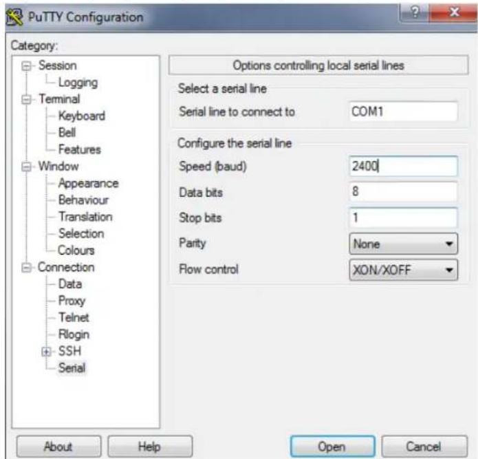
War 6. HaxMMte OKДЯpoJOnJKeHn.YctaHOBITE bBa DIP- nepeKIOUaTeIe Be6/SNMP-KapTb B NOJoxHeMe ON (BKJI) (peXMM HAcTPOIKN).HyperTermlal abTOMaTHueckn
NOJKNIOUaTe TcR K CNTeMe; eCIN 3TO HO He pONCXOIM, HaxMMte Ha 3HaQOK C N3OpaXeHMe M TeleOHa HA NaHEI INHCTpyMeHToB. IocNe yCTaHOBIIeHn CoEiHHeHn BOJNTe B CNTeMy
NoI perHCTpauOHn IMHeHm I napoIem aDMNHCTpato (no yMonuHn: admin/password, cyetom perHCTpa). IocNe BXOa B CNTeMy Ha 3KpaHne NoABJIaTcra IabHO MeHIO.
BoJe neop6HyIOHfOpMaUIO CM. B cIeNyUeM paZdene.
6. Habroka Be6/SNMP- nanopokolob
6.1.5 HacpoiKa B TeKCTOBOM peXnme
BdHnHom p3dene codepKaTc onncaHmHa n HactPouKn no ymoaHnIO dna HactpanBaHnC cnoNb3oBaHnEm Telnet/SSH-KnMeHTa, taKoro KaK HyperTerminal nn PuTTY.
TnabHoe MeHO

Dinneteep nonb3oBateen
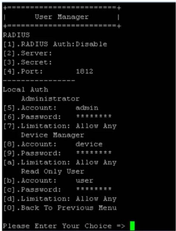
| № | Наменовские Onиданesуюшони | |
| [1] | RADIUS Auth Ustanabninaet, papeшени по Исторь�аиме RADIUS-ceрberpa. | Disable (эдпесено) |
| [2] | Server Мma RADIUS-ceрberpa. | |
| [3] | Secret Секетно Започnéддя работы с RADIUS-ceрberpo. | |
| [4] | Port Homep пораз RADIUS-ceрberpa. 1812 | |
| [5] | Administrator Account Pericntparu | admin |
| [6] | Рарь ладиминсторра password | |
| [7] | Administrator Limitation Orpanhi | Only in This LAN (тобко мз заим ЛBC) |
| [8] | Device Manager Account Pericntparu | device |
| [9] | Device Manager Password password | |
| [a] | Device Manager Limitation Or | Only in This LAN (тобко мз заим ЛBC) |
| [b] | Read Only User Account Per | user |
| [c] | Read Only User Password | password |
| [d] | Read Only User Limitation | Allow Any (разршить зл поб�и) |
6. HacrtpoiKa Be6/SNMP-npotoKoIob
HactpoKa TCP/IP
| +-------------------+ | |
| TCP/IP Setting | | |
| +-------------------+ | |
| [1].IPv4 Address: | 172.18.48.215 |
| [2].IPv4 Subnet Mask: | 255.255.255.0 |
| [3].IPv4 Gateway IP: | 172.18.48.1 |
| [4].IPv4 DNS or WINS IP: | 172.18.0.18 |
| [5].DHCPv4 Client: | Disable |
| [6].IPv6 Address: | fe80::230:abff:fe28:2e67 |
| [7].IPv6 Prefix Length: | 64 |
| [8].IPv6 Gateway IP: | :: |
| [9].IPv6 DNS IP: | :: |
| [a].DHCPv6: | Disable |
| [b].Host Name (NetBIOS): | TLNET |
| [c].System Contactor: | 10th Floor |
| [d].System Location: | 10th Floor Testing |
| [e].Auto-Negotiation: | Enable |
| [f].Speed: | 100M |
| [g].Duplex: | Full |
| [h].Status Stable: | 3 |
| [i].Telnet Idle Time: | 60 Seconds |
| [0].Back To Previous Menu | |
| Please Enter Your Choice => | |
| № | Hann | Meherabnne Ondca | Hne | No umohann |
| [1] | IPv4 | Address | IPv4-ádrec. | 192.168.001.100 |
| [2] | Macka noDCTeN | IPv4 | Hactroika Mackn noDCTeN IPv4. | 255.255.255.000 |
| [3] | IPv4 Gateway IP | IPv4-ádrec šluko3a IPv4. | IPv4. | 192.168.001.254 |
| [4] | IPv4 DNS or WINS IP | DNS or WINS IP | Сервр дomenhbox Имен IPv4 ил IP-aDrec WINS-ceрвera | 192.168.001.001 |
| [5] | DHCPv4 Client | IPv4-ádrec 3apnet на Исторьованиpe npotokona DHCPv4. | Enable (pa3peшени) | |
| [6] | IPv6 Address | IPv6-ádrec. | ||
| [7] | IPv6 Prefix Length | Дунna пешикca IPv6. | ||
| [8] | IPv6 Gateway IP | IPv4-ádrec šluko3a IPv6. | ||
| [9] | IPv6 DNS IP | IPv4-ádrec ssрета дomenhbox Имен IPv6. | ||
| [a] | DHCPv6 | Разшени/3apnet на Исторьованиpe npotokona DHCPv6. | Enable (pa3peшени) | |
| [b] | Host Name (NetBIOS) | Имя xoct-yзma за干嘛 Be6/SNMP-kapты. | TLNET | |
| [c] | System Contact | Кontakтуары Информацьо о систeme. | ||
| [d] | System Location | Информацьо o MeToToHaxOxJednii ChSCTeMbI. | ||
| [e] | Auto-Negotiation | Рazшени/3apnet на АВТOMATИЧЕСКОЕ сordacobanie的老codoctni peredaчдданьх (10/100 M6bit/c). | Enable (pa3peшени) | |
| [f] | Speed | В сичеспета на АВТOMATИCHЕСКОЕ сordacobanie的老bl можete задаь的老codoctb peredaчдданьх. | 100M | |
| [g] | Duplex | В сичеспета на АВТOMATИCHЕСКОЕ сordacobanie的老bl можete устовить дулковский ржим. | Full (noIbny) | |
| [h] | Status Stable | Вразим поворецki постоведию Историястуca. | 3 | |
| [i] | Telnet Idle Time | Hастрика bveмени постовения telnet-coeдиennentя. | 60 Seconds (60 sekund) |
Cetbo npametp
| +-----------------------------------+ | |
| | Network Parameter | | |
| +-----------------------------------+ | |
| [1].HTTP Server: | Enable |
| [2].HTTPS Server: | Enable |
| [3].Telnet Server: | Enable |
| [4].SSH/SFTP Server: | Enable |
| [5].FTP Server: | Disable |
| [6].Syslog: | Disable |
| [7].HTTP Server Port: | 80 |
| [8].HTTPS Server Port: | 443 |
| [9].Telnet Server Port: | 23 |
| [a].SSH Server Port: | 22 |
| [b].FTP Server Port: | 21 |
| [c].Syslog Server1: | |
| [d].Syslog Server2: | |
| [e].Syslog Server3: | |
| [f].Syslog Server4: | |
| [g].SNMP Get,Set Port: | 161 |
| [0].Back To Previous Menu | |
| Please Enter Your Choice => | |
Save and Exit (coxpanenne n bblxod)
CoxpaHeHBe BHeceHHbIX N3MeHeHIN BbIXoD.
7.Поррамma Precision Cooling Dashboard
ДлнaitрйснсгtemысnomоьPrecisionCoolingDashboardBbInonHITeCneDyuOuSeWARM:
War 1:Y6eIntecb TOM,HTO KAPTA SRCOOL60KCW noKNIOHcHaN K NOKAJIbHO CETM.
War 2: Pocne yctahOBHeHn CoedHHeHn Ha 3KpaHe NoBHeTcA CtpAHua BxOa B CHTeMy. BBeHte HmNtobateJia (no ymoHaHIO admin) n napoB (no ymOnuHaHIO password).

Tripp Lite Precision Cooling Dashboard Login
Copyright © 2015 Tripp Lite, Inc. All Rights Reserved.
Pumueyahu:
B Cnyae Heo3moKnoHcMn 6Oda B Cuemmy npu npabunbHm 8B0de UmeHu nOb3oAemaU npOra MoKem nompeobamcb dononHumEnbHa Hacmpouka cemu. IP-nocemb kOmnbomepa moKem omnuambcr am IP-nocemuycmpoMa SRCOOL60KCI.
- Ycmpoicmbo SRCOOL60KCW abomamumuecku bixohdum u3 cucmemb noce 30 muhm 63euecbure mekyem ceae.
IporpmaMPrecion Coodng Dashboard coepknt Tpu ochoBbix pa3de:Monitor("KoHTponb")Devic("YcTpoiCTBO")N System("CnTeMa").Bonee noDpo6Hyu HΦopMaio CM.B Pa3denax 7.1 u 7.2
7.1 KoHTpOJIb fYHKUHOHPOBaHnA
7.1.1 CratycnHΦopmaua
Ha cTpaHnue Monitor ("KoHTpOlb") npedctabneHb CTatyc yCTpoiCTBa KOHNIOHOPOBAHm INHΦopMaun O hem. HΦopMaun 6HOBJIeTc KaJdbie 10 cekynd nn HEmdIeHNO npn HaxaTM KnaBMn F5.
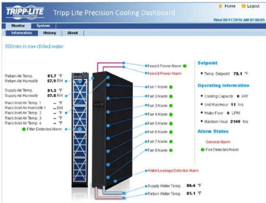
OrpaHnueHHa rapaHTHa cpoKoM 2 roTa
PpOaBaeu rapaHTnpyet OOTCTBHe 33HauHbHx DeEeKToB MaepHana Hm H3rOBoHneB B TeHHe 2 n9 (3a HcknoHcHem CII, KaHabn Mekckn, rpe cpoK deCTBHa rapaTHn coctBaaniet 1 ro) cMOMeHT aepoN okynn daHHoro H3ndnna npn cyOBnBn erO KNObnO3BOAHBn B COBTETCBTHn CO BcEMn pnpHMnHbMbN K Hemy HkaZAHANM. B CyIyue npoABNeHn KaHXN-n66 DeEeKToB MaepHana Hm H3rOBoHneB TbeHHe YkazAHORo NEpAa PpOda PpOdaeeocuyteBnert peMOHT Hm 3amEny daHoro H3ndnna HcKNOBnTeBNo CBOcHMy CymOpTeHNO. ObcynhBaHnene corNaChAoHeaR aepTnH BKnOAnBt Ce b6e noCTABKy 3anaChbNx TaehN BuINIOHe MeEObXDMxPb0T B cHTNE TEPKHECko O6NYKBHANbKOMpanNAHTRiP.
HACHTBHE HACTORI E HAPATTHH HEPACNTPOCTPAHRETO HA CUYAAN ECTCEBHHO H3N0CA MNI NIOPEKJEHIN B P3EYbATE ABAPM, HEHAJIENJAETO NOCIOHBNAH, HAPWHEH NIPABNIK KKTJYALATUN INX AIAHOTCM. PNOJAEAHIE HNEPODCTABTNIEHKAKHX YBO BPAJEXEHBX I TAPAHTRN 3A NKCHONHEHM PPMNIO 3NIOXEHNOB H B ATOHRIEM DOKVMEHTE. 3A MCKNHOHEHM CTYAAEB, 3APNEUHNHIX DECTBYOUIM 3AKOHODATELBOM, BCE IOPDA3YMEBAEMBLE TAPAHTRN BKNIOHYB BCE TAPAHTRN PNOIHOCTIN INI POLOJAKM NMI NCIOBJAOH NIO HA3HAENHIO, OPAMHNYBI NO PNOIDONKITENBOHCTN DECTBMR BBUEEYKA3AHBM I TAPAHTINMb CPOKOM; KPOME TOI, K3 HACTORI E HAPATTHB RBHMIBOPMAO 10KCHIOHYOCB BCE 106OHyBE, CUYAHIH NIKOCEHBYE BYtIKM. (B HeKOTOBx WATAx HC ONDyCAeT BBDChENr ORpAMHNYH N I pNOIDONKITENBOHCTN DECTBMR TEHNNHIN HBNX nnpa3yMaEBnRapAHTHB RABN BAM KOHNPTBIL BAM KOHNPTBIL BAM OPHNPOYXBAHIN XIN OCNBOEHHX BYbTKOB. BTHX cQYBAX BUBIENZKENHII EORpAMHNYH NIN KCNQUEHNNMOYRT HA BAC HE pANCPOCTPARHBcB. HACTOIAR PAHANTH PpOoCTABTNB BAM KOHNPTBIL BAM KOHNPTBIL BAM OPHNPOYXBAHIN XIN OCNBOEHHX BYbTKOB. A HABOP DpyTX BAHN XIN OPHNPOYXBAHIN B ABAHNMOCTN OT KPNDCNKUHN).
Tripp Lite; 1111 W. 35th Street; Chicago IL 60609; USA
BHMHAIWEIIOHNAIOBTOAAMDANHOHOYCTPOHTBAIOHOBATENBJIOKENY6EDHTCBNTOOMOHOIABINETCHPNOIDHM,COOTBECTSBYIOUIMIKINIEEONAOAEMORIPMUMEHNI. B CTR3Hc 60bHIMPA3HOo6bHmCNKHPCTBHXPNPMEHNEHN PPO3BOAtENTB No dAeT KAKMX NIO6 3aEBCEHHN HnRapaHTNH OTHOCATEBHO PnroHOCTDHnAHXIX3DENNI Dn KaKOrO-1N60 KOHKPTCHO PnmoHEHNR NIKX COOTBCTTBKaKHM-NIOKOHKPbTHmPteob8OBHMM.
IeHTHnKauNoHHbIe Homepa COoTBcTbHr HoMaTHBbHIM Tpe6BaHnM
BcHbEeepTtHbHbHbHbHbTbeHbOBeHHbHbHbHbHbHbHbHbHbHbHbHbHbHbHbHbHbHbHbHbHbHbHbHbHbHbHbHbHbHbHbHbHbHbHbHbHbHbHbHbHbHbHbHbHbHbHbHbHbHbHb HcIeepnepnepnepnepnepnepnepnepnepnepnepnepnepnepnepnepnepnepnepnepnepnepnepnepnepnepnepnepnepnepnepnepnepnepnepnepnepnepnepnepnepnepnepnepnepnepnepnepnepnep
HΦopMaJn IIO BbIOnHeHHIO Tpe6oBaHN IInpeKTHBbI WEE INI NOKyNaTeN I nepepa60TuKOB npOdyuKHN KOMNaHH Tripp Lite (IbJIaOnxHcpe3HdENTAMN Ebponeckoro co103a)

Cnnacho nnoKeHHM DApkeMbbs oBytmHa3aunOxTOBD 3eKTPNecKO H3eKTPHOHOrO 6OpDobAA (WEE) HcTnHInTeIbHbIX paCnpAekHeHNO e ee npMeHHNO, pRn NOKyIke Notpe6bTeAAA HOBORo 3eKTPNecKO Hnn 3eKTPHOHO 6OpDyobAHMA PPOH3BOCTBA KOMNAHMI Tripp Lite OHnNoyAot npABo HA:
PpOxyo 06opoyobuaHn no npHmuy"oMH 3a oHn HnHa 3KBbAeHTHO OCHOB (B 3ABMCHMOTH O KOHKpeTHOI CtpaHb)
0TnpaBky HOBo 06OpyDobAHn Ha nepebaOT Ky nocne oKOnHateNbHO BbpaOeTK erpca
KOMNTHTRippLitenoCToAHNOcoBepueHCTByET CBOO npDykuHn. B CB3M 3TMM BO3MOXHO H3MeHeHNE XApakTePHTM K6E pNDaHPtEnbHOrO yBedomneHH


Manufacturing Excellence.
1111 W. 35th Street, Chicago, IL 60609 USA - www.triplite.com/support