PDUMH32HVAT - Power strip Tripp Lite - Free user manual and instructions
Find the device manual for free PDUMH32HVAT Tripp Lite in PDF.
User questions about PDUMH32HVAT Tripp Lite
0 question about this device. Answer the ones you know or ask your own.
Ask a new question about this device
Download the instructions for your Power strip in PDF format for free! Find your manual PDUMH32HVAT - Tripp Lite and take your electronic device back in hand. On this page are published all the documents necessary for the use of your device. PDUMH32HVAT by Tripp Lite.
USER MANUAL PDUMH32HVAT Tripp Lite
Automatic Transfer Switch PDU
Models:
PDUMH30AT, PDUMH30ATNET, PDUMNH30AT2, PDUMH30HVAT, PDUMH30HVATNET, PDUMNH30HVAT2, PDUMH32HVAT, PDUMH32HVATNET, PDUMNH32HVAT2
Agency Model Numbers:
Important Safety Instructions 2
Feature Set Overview 4
Installation 4
Mounting the PDU 4
Connecting the PDU 7
Features
8
LED Diagrams 15
Configuration and Operation 19
Automatic Transfer Switch 19
Service
21
Warranty and Product Registration 22
Espanol
23
Français
45
Pycckn
67
Deutsch
89
WARRANTY REGISTRATION
Register your product today and be
automatically entered to win an ISOBAR®
surge protector in our monthly drawing!
triplite.com/warranty


TrippLite.Eaton.com/support
Copyright © 2023 Tripp Lite. All rights reserved.
Important Safety Instructions

This manual contains information concerning the proper installation and use of Tripp Lite's Rackmount Power Strips.
SAVE THESE INSTRUCTIONS.
Do not connect your power strip to an ungrounded outlet. Do not use it with extension cords or adapters that eliminate its connection to ground. Your power strip is designed for indoor use only. Install it away from heat emitting devices such as radiators and heat registers. Do not install where excessive moisture or other conductive contaminants are present. Never install
electrical wiring during a lightning storm.
The power requirement of each device connected to an outlet of your power strip must not exceed the Outlet Power Rating of your power strip (see Specifications). The total power requirements of all devices connected to your power strip must not exceed the Maximum Load Rating of your power strip (see Specifications).
CAUTION Only those who are properly trained or qualified to use this device should do so. Anyone who is not trained or qualified should not use this device unless it is under the supervision of someone who is properly trained or qualified to do so.
Children must be supervised to ensure that they do not use the device as a toy.
Never use the device if the cord and plug are damaged; if it is not working properly, or if it has been dropped or damaged, take it to an authorized service center for inspection and repair.
If the power cord is damaged, it must be replaced by the manufacturer, its authorized service agent, or by qualified personnel in order to avoid a danger.
- The PDU provides the convenience of multiple outlets, but DOES NOT provide surge or line noise protection for connected equipment.
- The PDU is designed for indoor use only, in a controlled environment, away from excess moisture, temperature extremes, conductive contaminants, dust or direct sunlight.
- Keep indoor ambient temperature between 32^ and 104^ (0^ and 40^)
- The PDU must be installed by a qualified technician only.
- Only those who are properly trained or qualified to use this device should do so. Anyone who is not trained or qualified should not use this device unless it is under the supervision of someone who is properly trained or qualified to do so.
- Do not attempt to mount the PDU to an insecure or unstable surface.
- Install in accordance with National Electrical Code standards. Be sure to use the proper overcurrent protection for the installation, in accordance with the plug/ equipment rating.
Important Safety Instructions
- Connect the PDU to an outlet that is in accordance with your local building codes and that is adequately protected against excess currents, short circuits and earth faults.
- The electrical outlets supplying power to the equipment should be installed near the equipment and easily accessible.
- Do not connect the PDU to an ungrounded outlet or to extension cords or adapters that eliminate the connection to ground.
- Be sure to provide a local disconnect device on any models that are permanently installed without a plug that is easily accessible.
- Never attempt to install electrical equipment during a thunderstorm.
- Individual equipment connected to the PDU should not draw more current than the individual PDU's outlet's rating.
- The total load connected to the PDU must not exceed the maximum load rating for the PDU.
- Do not attempt to modify the PDU, input plugs or power cables.
- Do not drill into or attempt to open any part of the PDU housing. There are no user-serviceable parts inside.
- Do not attempt to use the PDU if any part of it becomes damaged.
- This equipment is not suitable for use in locations where children are likely to be present.
- Use of this equipment in life support applications where failure of this equipment can reasonably be expected to cause the failure of the life support equipment or to significantly affect its safety or effectiveness is not recommended.
The AC Main tolerance of this equipment is +6 / - 10%
Feature Set Overview
| Model Number | Outlet Control (Yes/No)? | Outlet LED Indicator (Yes/No)? | Shipped with SNMP Slot (Yes/No)? | Shipped with SNMP Card Installed (Yes/ No)? |
| PDUMH30AT | No No No No | |||
| PDUMH30ATNET | Yes Yes Yes Yes | |||
| PDUMNH30AT2 No | No Yes Yes | |||
| PDUMH30HVAT | No No No No | |||
| PDUMH30HVATNET | Yes Yes Yes Yes | |||
| PDUMNH30HVAT2 No | No Yes Yes | |||
| PDUMH32HVAT | No No No No | |||
| PDUMH32HVATNET | Yes Yes Yes Yes | |||
| PDUMNH32HVAT2 No | No Yes Yes |
Installation
Mounting the PDU
The PDU supports 2U rack mounting or surface mounting (e.g. on a wall, on a desk or under a counter).
Note: The user must determine the fitness of hardware and procedures before mounting. The PDU and included hardware are designed for common rack and rack enclosure types and may not be appropriate for all applications. Exact mounting configurations may vary.
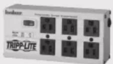
2U Rack Mounting
1A Attach the included mounting brackets to the sides of the PDU with the included screws.
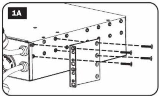
2A After attaching the brackets, position the PDU in the rack and install four user-supplied screws through the bracket ears and into the rack rails.
Installation
Wall Mounting (not applicable to series AG-0151 for PDUMH32HVAT, PDUMNH32VAT2 or PDUMH32HVATNET)
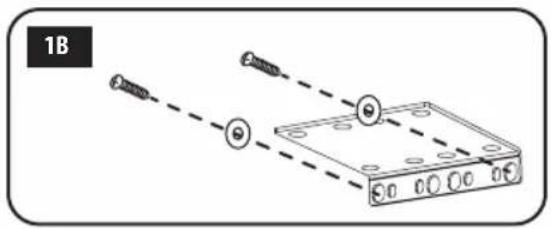
1B
Attach one of the supplied mounting brackets to the wall with user-supplied screws. Make sure screws and any other hardware are appropriate for the surface type.
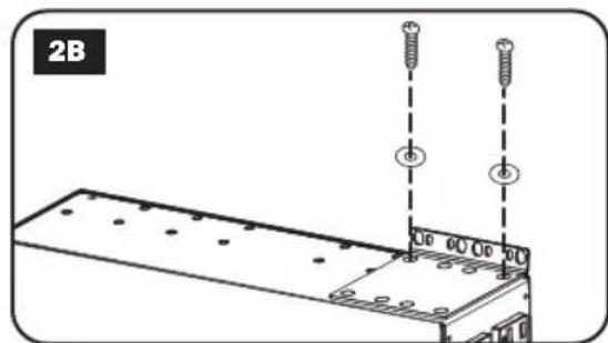
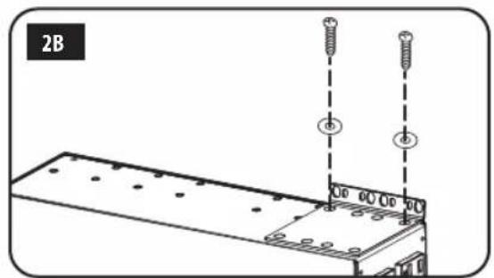
2B
Attach a mounting bracket to the PDU with the included screws.
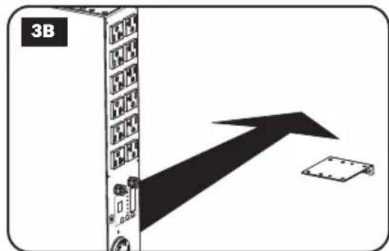
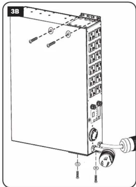
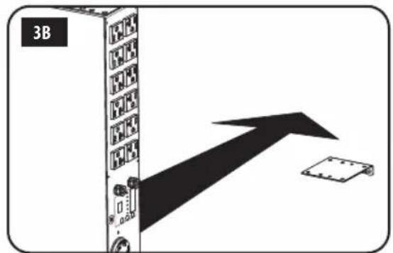
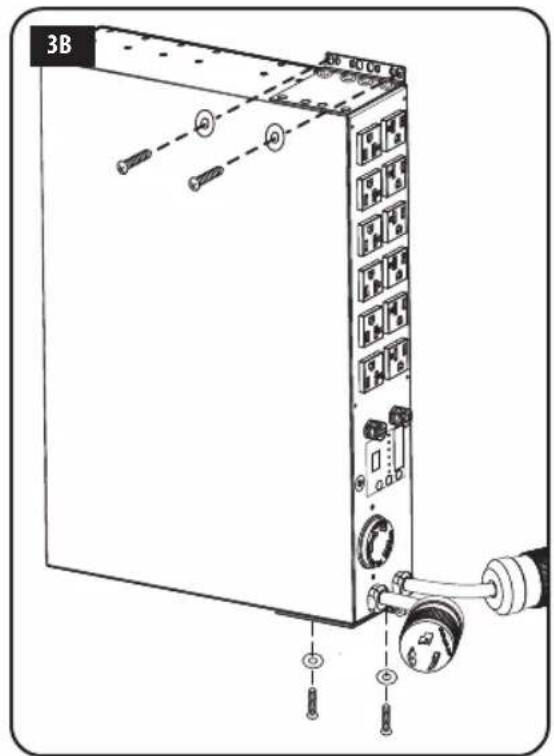
3B
Place the PDU on the wall-mounted bracket and secure the PDU to the bracket and wall as shown.

Installation
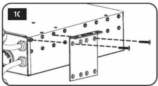
Surface Mounting
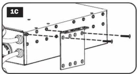
1C Attach the included mounting brackets to the sides of the PDU with the included screws.
Note: If you need to change the orientation of the PDU to match the mounting surface, rotate the mounting brackets in 90^ increments as required before attaching.
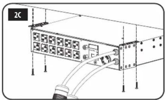
2C Mount the PDU to a stable surface by inserting four user-supplied screws through the bracket ears and into appropriate mounting holes. Make sure the mounting surface and screws are capable of supporting the combined weight of the PDU and any attached equipment cords.
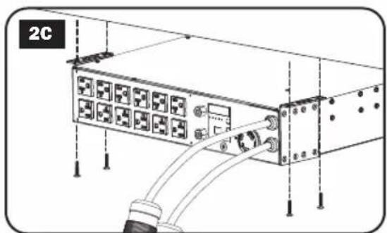
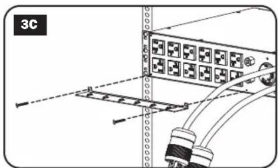
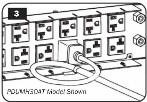
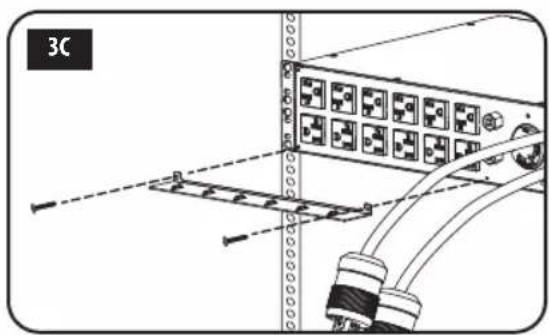
3C Attach Cord Retention Brackets
(Optional): Attach the cord retention brackets to the PDU with the included screws.
Installation
Connecting the PDU
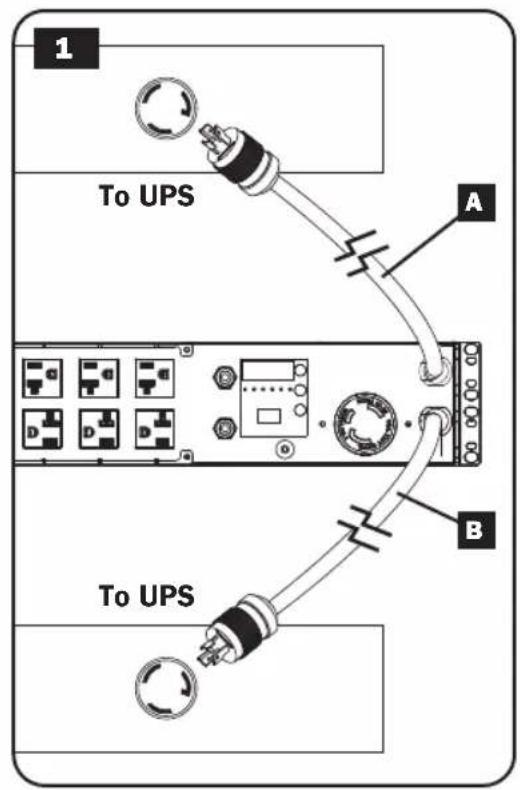
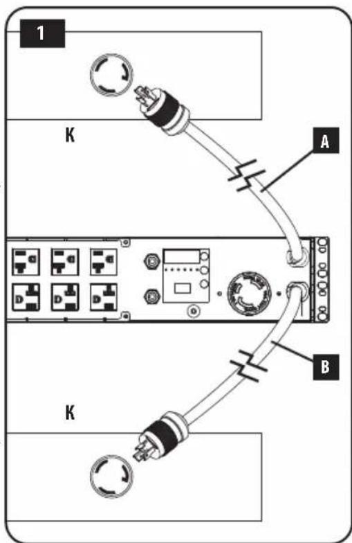
Note: The PDU includes two input power cords: Primary and Secondary. They should be connected to two separate AC power sources.
1 Connect PDU Input Plugs: Connect the Primary input plug A to a preferred source of grounded AC power (120V for PDUMH30AT, PDUMNH30AT2 & PDUMH30ATNET; 200-240V for PDUMH30HVAT, PDUMNH30HVAT2, PDUMH30HVATNET, PDUMH32HVAT, PDUMNH32HVAT2 & PDUMH32HVATNET), such as a Tripp Lite SmartOnline® UPS System. Under normal operating conditions, the PDU will distribute AC power from the Primary input source. Connect the Secondary input plug B to an alternative source of grounded AC power (120V for PDUMH30AT, PDUMNH30AT2 & PDUMH30ATNET; 200-240V for PDUMH30HVAT, PDUMNH30HVAT2, PDUMH30HVATNET, PDUMH32HVAT, PDUMNH32HVAT2 & PDUMH32HVATNET), For proper ATS (automatic transfer switch) function, do not plug the Secondary input into the same power source as the Primary input. The PDU will distribute AC power from the Secondary input only if the Primary input becomes unavailable due to an outage or power quality problem. (See Configuration and Operation section for more information about the ATS function.)
Installation

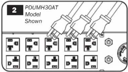
Connect Equipment to the PDU: Do not exceed the total load rating of the PDU or output load bank. The connected equipment load will be displayed on the digital load meter in amperes.

Cord Retention (Optional): If you connected the cord retention brackets to the PDU, attach each equipment power cord to a cord retention bracket by looping the cord and securing it to an attachment point with one of the included cable ties. Make sure that each power cord can be unplugged from the PDU without removing the cable tie.
Features
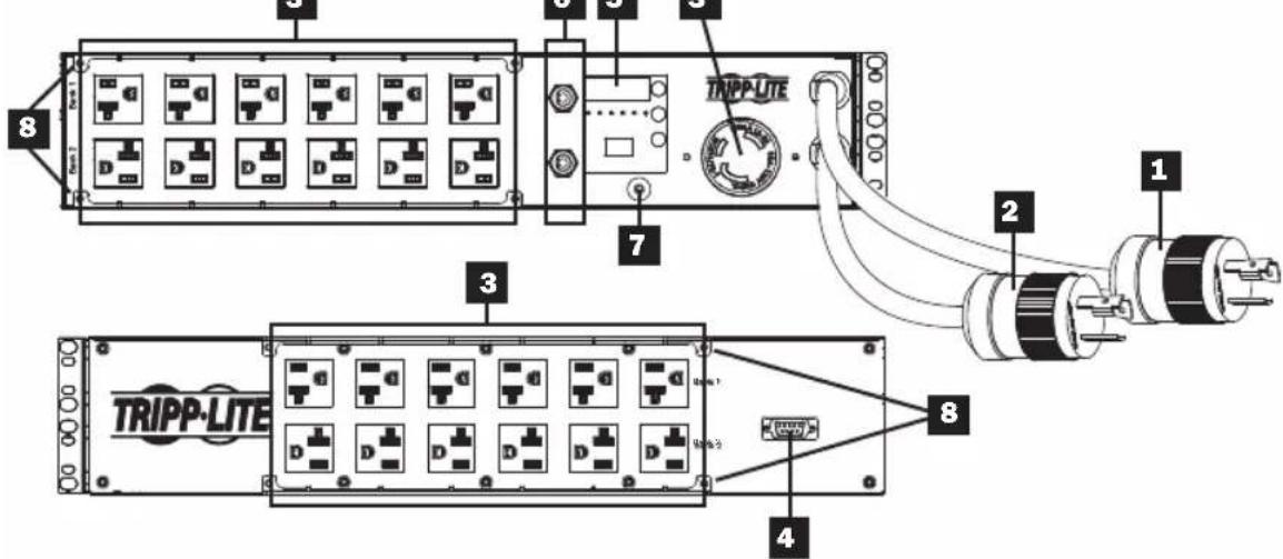
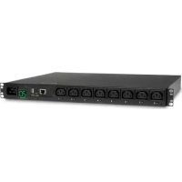
PDUMH30AT
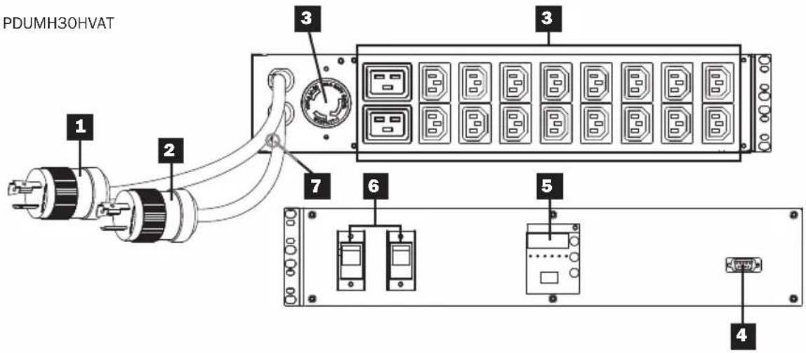
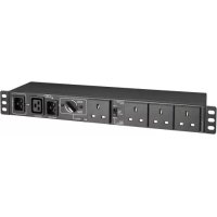
PDUMH30HVAT
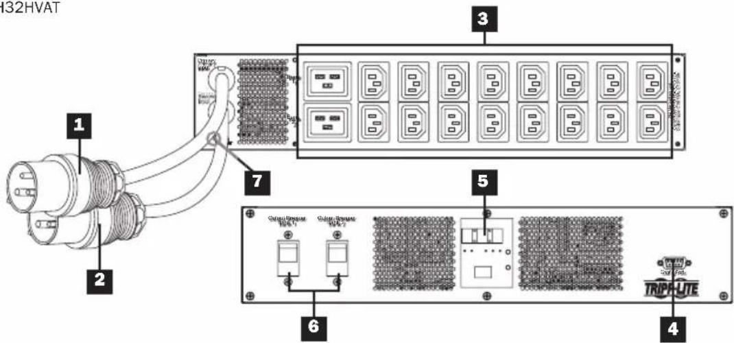
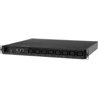
PDUMH32HVAT
Features
PDUMNH30AT2
Features
PDUMNH30HVAT2
Features
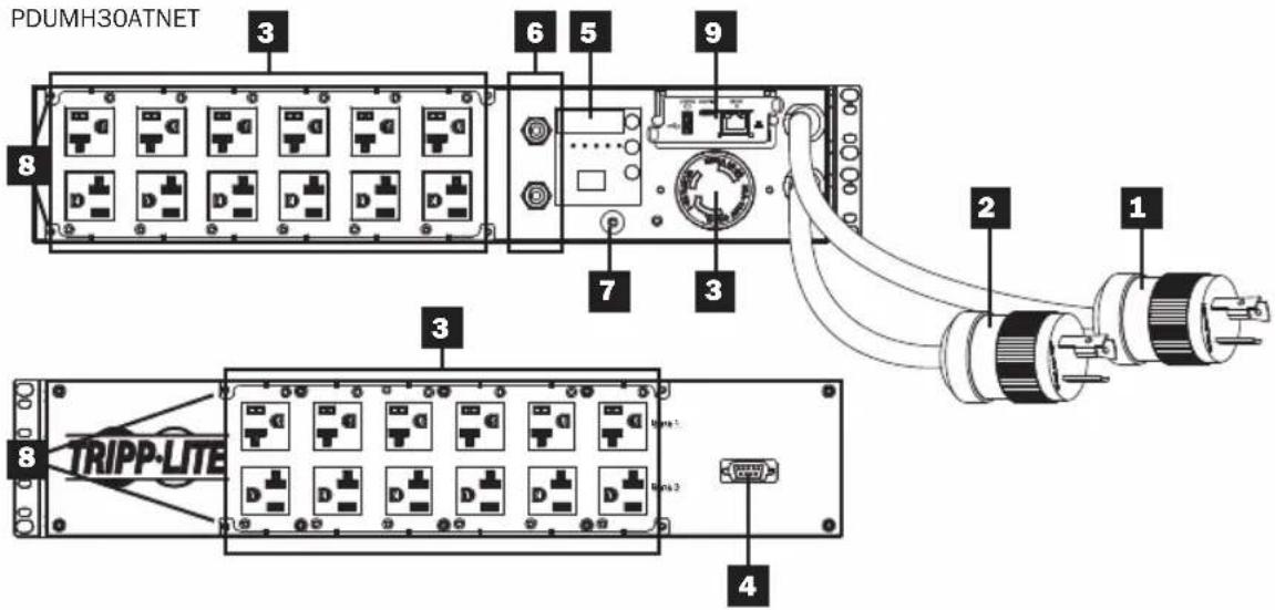
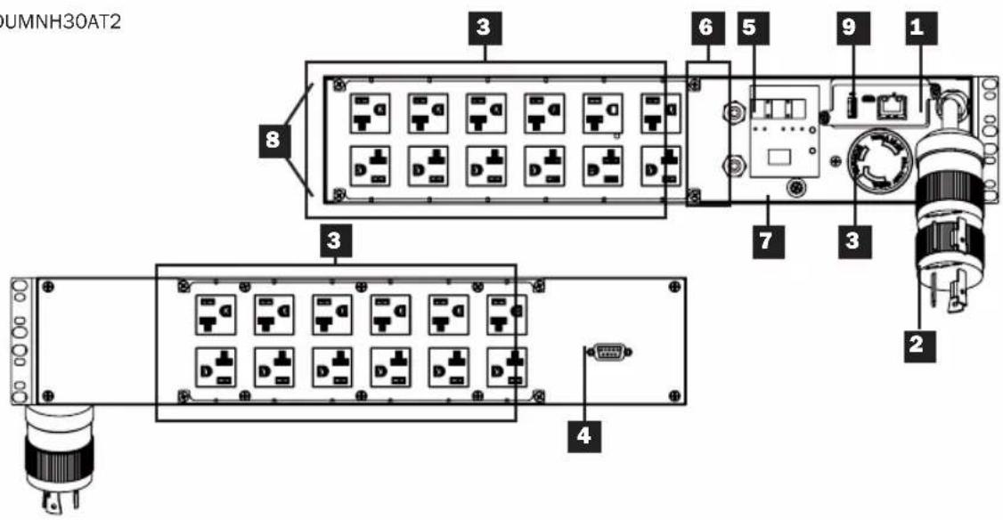
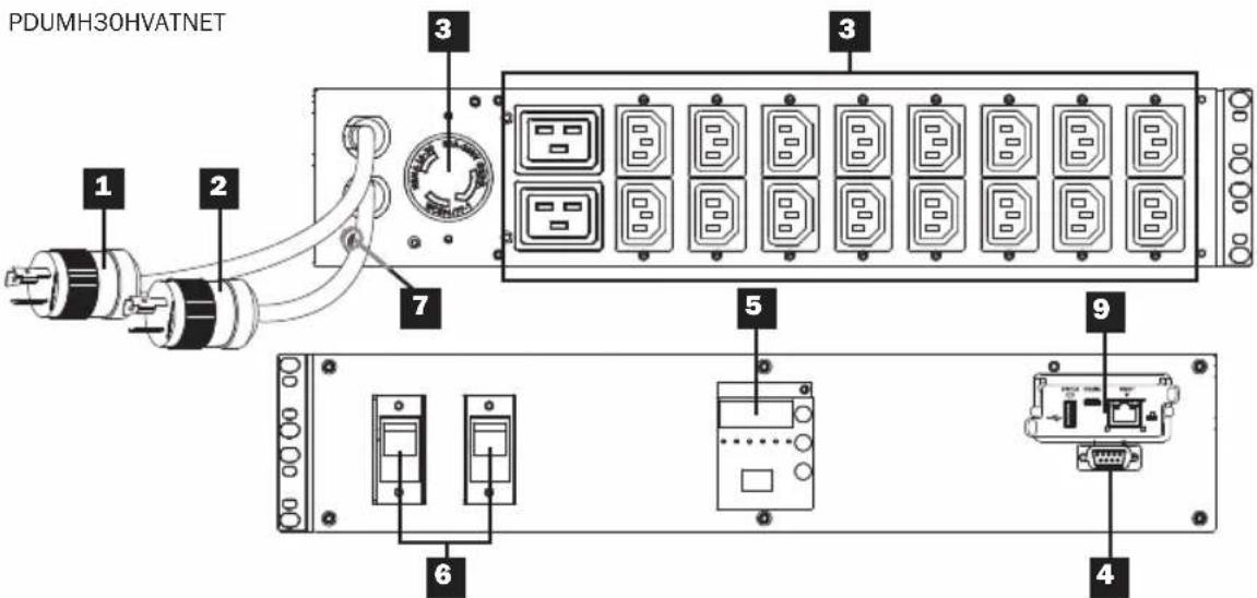
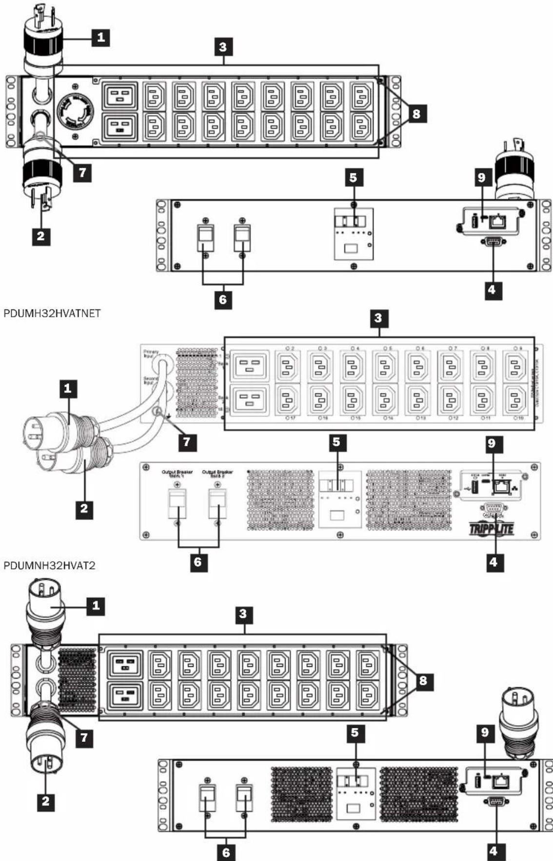
Primary Input Cord
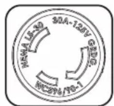
The cord is permanently attached to the PDU and has a NEMA L5-30P (PDUMH30AT, PDUMNH30AT2 & PDUMH30ATNET) or NEMA L6-30P (PDUMH30HVAT, PDUMNH30HVAT2 & PDUMH30HVATNET) twist-lock plug or IEC 309 32A (PDUMH32HVAT, PDUMNH32HVAT2 & PDUMH32HVATNET) plug.
2 Secondary Input Cord
The cord is permanently attached to the PDU and has a NEMA L5-30P (PDUMH30AT, PDUMNH30AT2 & PDUMH30ATNET) or NEMA L6-30P (PDUMH30HVAT, PDUMNH30HVAT2 & PDUMH30HVATNET) twist-lock plug or IEC 309 32A (PDUMH32HVAT, PDUMNH32HVAT2 & PDUMH32HVATNET) plug.
3 Switched Outlets (PDUMH30ATNET, PDUMH30HVATNET, PDUMH32HVATNET):
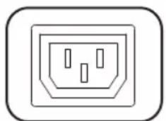
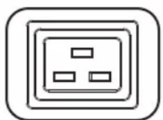
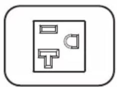
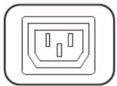
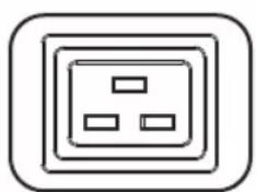
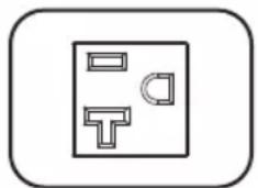
During normal operation, the outlets distribute AC power to connected equipment. The NEMA 5-15/20R, L5-30R, IEC 320 C13, IEC 320 C19 and L6-30R outlets may be switched On and Off via software control. When an outlet is live, the associated LED illuminates.
Unswitched Outlets (PDUMH30AT, PDUMNH30AT2, PDUMH30HVAT, PDUMNH30HVAT2, PDUMH32HVAT, PDUMNH32HVAT2): The NEMA 5-15/20R, L5-30R, IEC 320 C13, IEC 320 C19 and L6-30R outlets receive power from either input source, but are not individually switchable.
IEC 320 C13 Outlets (PDUMH30HVAT, PDUMNH30HVAT2, PDUMH30HVATNET, PDUMH32HVAT, PDUMNH32HVAT2 & PDUMH32HVATNET): 10A (200-240V)
IEC 320 C19 Outlets (PDUMH30HVAT, PDUMNH30HVAT2, PDUMH30HVATNET, PDUMH32HVAT, PDUMNH32HVAT2 & PDUMH32HVATNET): 16A (200-240V)
NEMA 5-15/20R Outlets (PDUMH30AT, PDUMNH30AT2 & PDUMH30ATNET): 20A (120V)
NEMA L5-30R Outlet (PDUMH30AT, PDUMNH30AT2 & PDUMH30ATNET): 30A (120V)
NEMA L6-30R Outlet (PDUMH30HVAT, PDUMNH30HVAT2 & PDUMH30HVATNET): 30A (200-240V)

Factory Port: This port is reserved for configuration by factory-authorized personnel only. Do not connect anything to this port.
Features
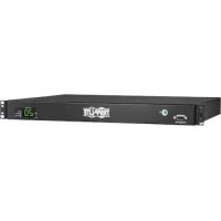
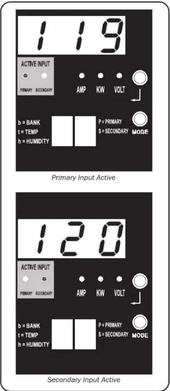
5 Digital LED Display and Load Meter (Ammeter)
A 3-Digit Display: Shows measured or calculated amperage, kilowatt or voltage values.
Enter Button: Scroll through DISPLAY and CONFIGURATION options using this button. While in DISPLAY mode, a short press switches the display between AMPS, KW and VOLTS. While in CONFIGURATION mode, a long press changes configuration items (TEMPERATURE, AUTO SCROLL, LED BRIGHTNESS). Pressing the Enter button and Mode button simultaneously displays the unit's IP address (select models).
Mode Button: A short press of
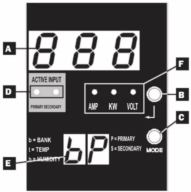
this button cycles through each of the modes (PRIMARY, SECONDARY, BANK, TEMP, HUMIDITY) of the present category (DISPLAY or CONFIGURATION) for both primary and secondary inputs. A long press switches between DISPLAY and CONFIGURATION. Pressing the Mode button and Enter button simultaneously displays the unit's IP address (models with WEBCARDLX installed).
*TEMP/HUMIDITY only available if optional ENVIROSENSE module is attached.
Active Input LEDs: Indicate whether the primary or secondary active input is powering the output.
E 2-Digit Display: Indicates whether the value shown on the 3-digit display represents primary, secondary, bank, temperature or humidity.
Display Modes:
P: The 3-digit display is showing information related to the primary AC input. (Unit LEDs dictate what data is shown.)
S: The 3-digit display is showing information related to the secondary AC input. (Unit LEDs dictate what data is shown.)
b 'n': The 3-digit display is showing information related to the output bank number ('n').
t 'n': The 3-digit display is showing temperature for sensor ('n'). (Units for F or C are configured in CONFIGURATION mode.)
h 'n': The 3-digit display is showing humidity for sensor ('n').
F Units LEDs: The AMPS, KW and VOLT LEDs are used to illustrate the units of data displayed on the 3-digit display.
Features
Amp LED: When selected, the load is displayed in amps on the 3-digit display.
kW LED: When selected, the load is displayed in kilowatts on the 3-digit display.
Volt LED: When selected, the voltage is displayed on the 3-digit display.
6 Output Circuit Breakers: Two circuit breakers protect equipment connected to each load bank against overloads. If a breaker trips, the circuit is overloaded and you need to reduce the load connected to the circuit breaker's load bank. Press the circuit breaker button to reset and restore power.
Ground Connection: Allows you to connect a user-supplied ground wire between the PDU and any equipment that requires a chassis ground.
8 Cord Retention Bracket (Optional Installation): When installed on the PDU, cord retention brackets provide secure attachment points for connected equipment power cords.
Network Management Card (PDUMH30ATNET, PDUMNH30AT2, PDUMH30HVATNET, PDUMNH30HVAT2, PDUMH32HVATNET,
PDUMNH32HVAT2): The WEBCARDLX accessory allows you to operate the PDU as a managed network device, accessible via SNMP network management platform, web browser, SSH or telnet. For details, refer to the WEBCARDLX Owner's Manual included with this product.
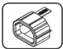
NOT SHOWN-C14 Plug-Lock Insert Sleeve (Optional): Use the included plastic sleeves to secure C13 power cords to C14 inlets. Fit the sleeve over the end of the cord, making sure the pull-tabs remain outside the cord and the fit is secure. To unplug equipment properly, grip both the cord and the insert's tabs at the same time and pull.
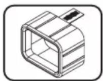
NOT SHOWN-C20 Plug-Lock Insert Sleeve (Optional): Use the included plastic sleeves to secure C19 power cords to C20 inlets. Fit the sleeve over the end of the cord, making sure the pull-tabs remain outside the cord and the fit is secure. To unplug equipment properly, grip both the cord and the insert's tabs at the same time and pull.
LED Diagrams
Display Modes
Primary Source Measurements
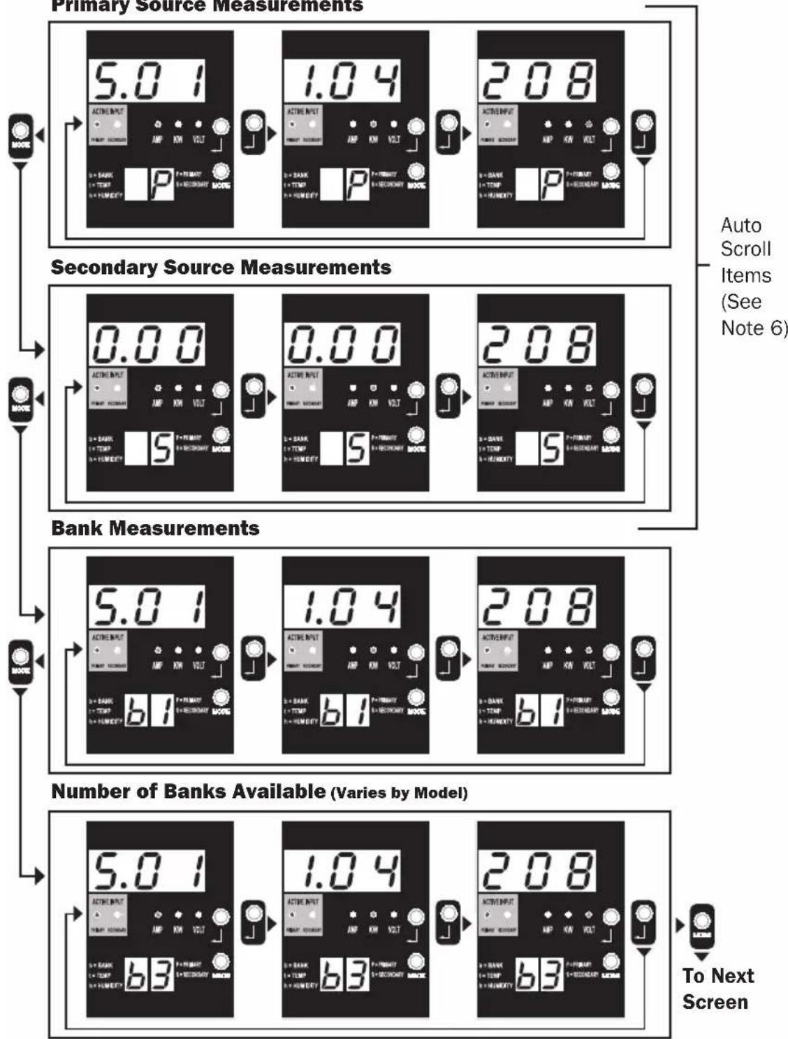
Note 1: Press Mode button to go to the next Display mode (vertical movement on this document). Note the Amps, kW or Volt submode will be remembered.
Note 2: Press Enter button to go to the next sub-mode (horizontal movement on this document).
Note 3: The Active Input LEDs will always show the present source powering the load. (The example images above all assume the presently selected source is the Primary. Note that if the Secondary source were selected, that LED would illuminate and the Primary LED would be dim. If neither source is valid, then both the Primary and Secondary source LEDs would be dim).
Note 4: Press and hold both Mode and Enter buttons for 2 seconds to show the IP address of the connected SNMP card.
Note 5: Press and hold MODE button for 2 seconds to switch to Control modes (this will go to the FIRST control mode).
Note 6: When Auto Scroll is enabled, after 10 seconds of inactivity, the display will continuously transition between primary amps, kW and volts and secondary amps, kW and volts, then wrap back to primary amps.
LED Diagrams
Display Modes
Temperature Display Mode (Only Available if EnviroSense Connected)
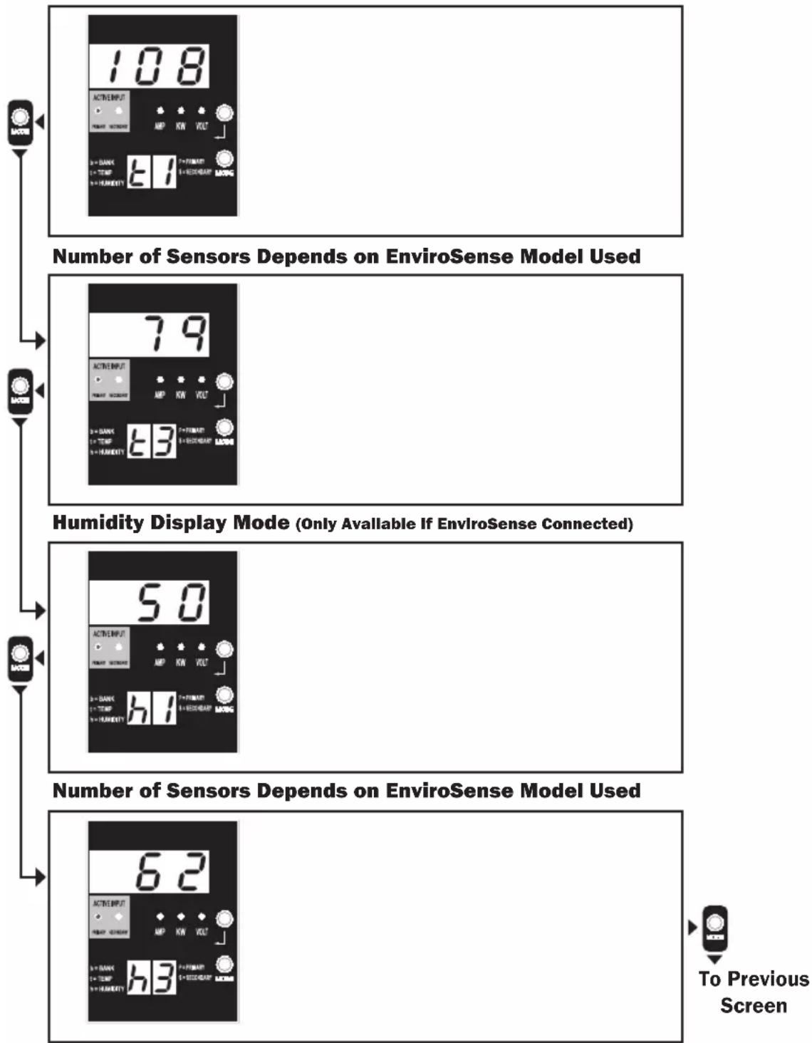
Note 1: Press Mode button to go to the next Display mode (vertical movement on this document). Note the Amps, kW or Volt submode will be remembered.
Note 2: Press Enter button to go to the next sub-mode (horizontal movement on this document).
Note 3: The Active Input LEDs will always show the present source powering the load.
Note 4: Press and hold both Mode and Enter buttons for 2 seconds to show the IP address of the connected SNMP card.
Note 5: Press and hold MODE button for 2 seconds to switch to Control modes. (This will go to the FIRST control mode.)
LED Diagrams
IP Address Display
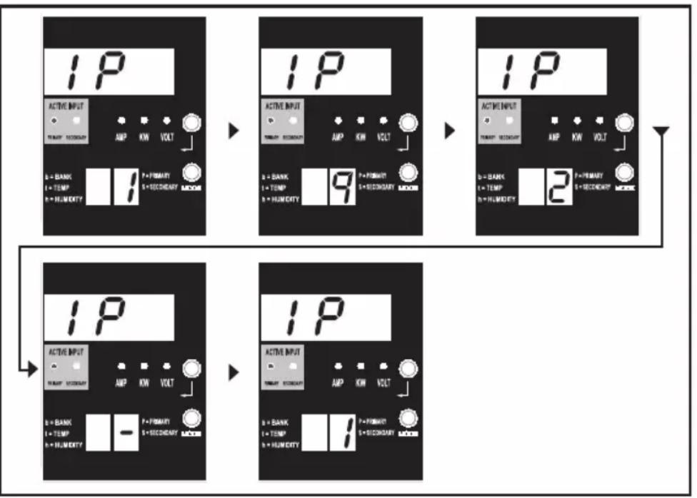
Note 1: IP Address display: the top 3 digit display will show "IP". The bottom right 2-digit display will show one IP address digit at a time separated by blanks to identify each digit. Decimal points and colons will be shown as hyphens. (Note this display supports IPv4 AND IPv6 addresses.)
Note 2: The display will automatically transition back to whatever mode it came from after displaying the IP address.
LED Diagrams
Control Modes
Celsius or Fahrenheit Configuration (Only Shown if EnviroSense Connected)
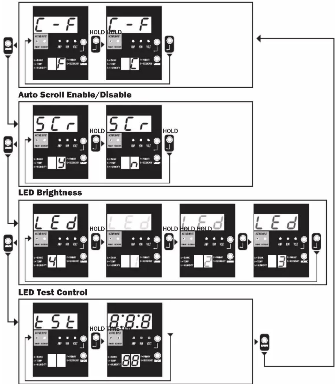
Note 1: Press Mode button to go to the next Display mode (vertical movement on this document). Note the Amps, kW or Volt submode will be remembered.
Note 2: Press and HOLD Enter button for 2 seconds to change the configuration. Whatever configuration is shown is what the unit is configured for (horizontal movement on this document).
Note 3: The Active Input LEDs will always show the present source powering the load.
Note 4: Press and hold both Mode and Enter buttons for 2 seconds to show the IP address of the connected SNMP card.
Note 5: Press and hold MODE button for 2 seconds to switch to Display modes (this will go to the FIRST Display mode).
Note 6: C-F display allows the unit to be configured to display Celsius or Fahrenheit. This mode will be omitted if EnviroSense is not connected (changes will be remembered in NVR).
Note 7: SCr Auto scroll enable or disable. When set to y (enabled), the unit will automatically scroll through Display items (See Display modes on page 10 for details). When set to n, the unit will not automatically scroll (changes will be remembered in NVR).
Note 8: LED brightness control - Set this to 1-4 for the desired illumination intensity (changes will be remembered in NVR).
Note 9: tSt LED Test control - Press and hold Enter button for 2 seconds to initiate an LED test where all LEDs will be illuminated for 6 seconds.
Configuration and Operation
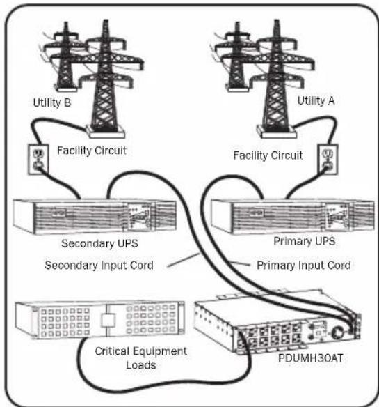
Automatic Transfer Switch
When the Primary and Secondary inputs are both connected to Tripp Lite UPS Systems, the PDU operates as an Automatic Transfer Switch, providing redundant input power for high-availability applications. Under normal operating conditions, the PDU will distribute power from the Primary input source, switching to the Secondary input source under certain conditions. The PDU will switch to the Primary source whenever it is "Good," according to the PDU input voltage definitions (see below).
Preferred Configuration
The Automatic Transfer Switch function provides increased availability when the Primary and Secondary inputs of the PDU are connected to separate Tripp Lite UPS Systems that are connected to separate utility power sources. For maximum availability, Tripp Lite recommends using matching SmartOnline UPS Systems with pure sine wave output for the Primary and Secondary input power sources. The automatic transfer switch function will be compromised if the primary and secondary inputs are connected to the same utility power source.
Warning: DO NOT connect the primary input to a line-interactive UPS, due to transfer-time issues, or to any source that does not supply a pure sine wave. Such sources may be used to power the secondary input.
Automatic Transfer Switch Source Selection
The PDU will power up if one of the input sources is greater than the minimum startup voltage. In normal operation (after power-up), if the presently selected source (primary or secondary) degrades to a lesser condition, the unit should switch to the alternate source, if that source is of better quality. The unit prefers the primary source, and will always switch to it in the event both sources are of the same (fair or good) quality. If the present source is becoming bad and the alternate source is at least fair, the unit will switch to the alternate source.
Configuration and Operation
PDU Power Source Selection Parameters
| PDUMH30AT, PDUMNH30AT2 & PDUMH30ATNET | PDUMH30HVAT, PDUMNH30HVAT2 PDUMH30HVATNET, PDUMH32HVAT, PDUMNH32HVAT2 & PDUMH32HVATNET | |
| Nominal Voltage 120V 200- | 240V | |
| Minimum Startup Voltage 85V 163V | ||
| "Good" Voltage Range 99-139V 172-266V | ||
| "Fair" Voltage Range 75-98V 144-171V | ||
| "Bad" Voltage Range 0-74V 0-143V |
After installing the PDU and connecting equipment, you may test the Automatic Transfer Switch function by temporarily shutting down the UPS system connected to the Primary AC input. When the Primary input UPS is no longer supplying AC power, the PDU will switch from the Primary input to the Secondary input, and the Secondary Active Input LED will be lit. When the Primary input UPS has been restarted and resumes supplying AC power, the PDU will switch back to the Primary input, and the Primary Active Input LED will be lit.
Note: The primary and secondary inputs must be connected to separate sources of utility power. The automatic transfer switch function will be compromised if the primary and secondary inputs are connected to the same utility power source. Do not perform a test with equipment that must remain in productive operation. Any test procedure must prepare for the contingency that the equipment may lose power. Do not test the PDU by detaching power cords connected to live power sources, as this eliminates the connection to ground and places your equipment at risk.
PDUMH30ATNET Model Shown
Configuration and Operation
Remote Monitoring and Control (Select Models)
Models PDUMH30ATNET, PDUMNH30AT2, PDUMH30HVATNET, PDUMNH30HVAT2, PDUMH32HVATNET and PDUMNH32HVAT2 provide remote monitoring, outlet control and more via Web browser, telnet and SNMP-based Network Management Systems. For more information about configuration and operation of the PDU via the PowerAlert Web browser interface, refer to the WEBCARDLX Owner's Manual included with this product or downloadable at triplite.com.
Load "Ramping" on Startup: All models arrive from the factory programmed so that, when first powered up, their outlets turn on in sequential order at intervals of approximately 250 ms. This prevents circuit overloads by staggering the startup of multiple devices. Models PDUMH30ATNET, PDUMH30HVATNET and PDUMH32HVATNET support user-programmable startup of outlets in any order or time interval. This ensures that network items are turned on in the proper sequence with the appropriate delay, so that network items are reliably discovered on startup.
Programmable Load "Shedding" During a Power Failure: In the event the primary power source fails and the PDU is relying on the secondary power source, load shedding allows you to program the shutoff of specific outlets at timed intervals. This enables you to turn off less critical loads (monitors, for example) to maximize the UPS runtime for the most critical items.
Service
Your Tripp Lite product is covered by the warranty described in this manual. A variety of Extended Warranty and On-Site Service Programs are also available from Tripp Lite. For more information on service, visit tripplite.com/support. Before returning your product for service, follow these steps:
-
Review the installation and operation procedures in this manual to insure that the service problem does not originate from a misreading of the instructions.
-
If the problem continues, do not contact or return the product to the dealer. Instead, visit tripplite.com/support.
-
If the problem requires service, visit tripplite.com/support and click the Product Returns link. From here you can request a Returned Material Authorization (RMA) number, which is required for service. This simple on-line form will ask for your unit's model and serial numbers, along with other general purchaser information. The RMA number, along with shipping instructions will be emailed to you. Any damages (direct, indirect, special or consequential) to the product incurred during shipment to Tripp Lite or an authorized Tripp Lite service center is not covered under warranty. Products shipped to Tripp Lite or an authorized Tripp Lite service center must have transportation charges prepaid. Mark the RMA number on the outside of the package. If the product is within its warranty period, enclose a copy of your sales receipt. Return the product for service using an insured carrier to the address given to you when you request the RMA.
Warranty and Product Registration
2-Year Limited Warranty
Seller warrants this product, if used in accordance with all applicable instructions, to be free from original defects in material and workmanship for a period of two (2) years from the date of initial purchase. If the product should prove defective in material or workmanship within that period, Seller will repair or replace the product, at its sole discretion.
THIS WARRANTY DOES NOT APPLY TO NORMAL WEAR OR TO DAMAGE RESULTING FROM ACCIDENT, MISUSE, ABUSE OR NEGLECT. SELLER MAKES NO EXPRESS WARRANTYES OTHER THAN THE WARRANTY EXPRESSLY SET FORTH HEREIN. EXCEPT TO THE EXTENT PROHIBITED BY APPLICABLE LAW, ALL IMPLIED WARRANTYES, INCLUDING ALL WARRANTYES OF MERCHANTABILITY OR FITNESS, ARE LIMITED IN DURATION TO THE WARRANTY PERIOD SET FORTH ABOVE; AND THIS WARRANTY EXPRESSLY EXCUSES ALL INCIDENTAL AND CONSEQUENTIAL DAMAGES. (Some states do not allow limitations on how long an implied warranty lasts, and some states do not allow the exclusion or limitation of incidental or consequential damages, so the above limitations or exclusions may not apply to you. This warranty gives you specific legal rights, and you may have other rights which vary from jurisdiction to jurisdiction.)
WARNING: The individual user should take care to determine prior to use whether this device is suitable, adequate or safe for the use intended. Since individual applications are subject to great variation, the manufacturer makes no representation or warranty as to the suitability or fitness of these devices for any specific application.
PRODUCT REGISTRATION
Visit triplite.com/warranty today to register your new Tripp Lite product. You'll be automatically entered into a drawing for a chance to win a FREE Tripp Lite product!*
- No purchase necessary. Void where prohibited. Some restrictions apply. See website for details.
FCC Notice, Class A
This device complies with part 15 of the FCC Rules. Operation is subject to the following two conditions: (1) This device may not cause harmful interference, and (2) this device must accept any interference received, including interference that may cause undesired operation.
Note: This equipment has been tested and found to comply with the limits for a Class A digital device, pursuant to part 15 of the FCC Rules. These limits are designed to provide reasonable protection against harmful interference when the equipment is operated in a commercial environment. This equipment generates, uses, and can radiate radio frequency energy and, if not installed and used in accordance with the instruction manual, may cause harmful interference to radio communications. Operation of this equipment in a residential area is likely to cause harmful interference in which case the user will be required to correct the interference at his own expense. The user must use shielded cables and connectors with this equipment. Any changes or modifications to this equipment not expressly approved by Tripp Lite could void the user's authority to operate this equipment.
Regulatory Compliance Identification Numbers
For the purpose of regulatory compliance certifications and identification, your Tripp Lite product has been assigned a unique series number. The series number can be found on the product nameplate label, along with all required approval markings and information. When requesting compliance information for this product, always refer to the series number. The series number should not be confused with the marking name or model number of the product.
WEEE Compliance Information for Tripp Lite Customers and Recyclers (European Union)

Under the Waste Electrical and Electronic Equipment (WEEE) Directive and implementing regulations, when customers buy new electrical and electronic equipment from Tripp Lite they are entitled to:
- Send old equipment for recycling on a one-for-one, like-for-like basis (this varies depending on the country)
- Send the new equipment back for recycling when this ultimately becomes waste
Tripp Lite has a policy of continuous improvement. Specifications are subject to change without notice. Photos and illustrations may differ slightly from actual products.

TrippLite.Eaton.com/support
Tomacorrientes IEC 320 C19
(PDUMH30HVAT, PDUMNH30HVAT2,
PDUMH30HVATNET, PDUMH32HVAT, PDUMNH32HVAT2 y
PDUMH32HVATNET):
16 A (200-240 V)
NEMA 5-15/20R
Tomacorrientes
(PDUMH30AT,
PDUMNH30AT2 &
PDUMH30ATNET):
20A (120V)
NEMA L5-30R
Tomacorrientes
(PDUMH30AT,
PDUMNH30AT2 y
PDUMH30ATNET):
24A (120V)
NEMA L6-30R
Tomacorrientes
(PDUMH3OHVAT,
PDUMNH30HVAT2 y
PDUMH30HVATNET):
24A (200-240V)


Characteristicas

PykoBoDCTBO NOIb30BaTeJIa
PDU c aBtOMaTnueckn BBoDom pe3epBa
Moden:
PDUMH30AT, PDUMH30ATNET, PDUMNH30AT2, PDUMH30HVAT, PDUMH30HVATNET, PDUMNH30HVAT2, PDUMH32HVAT, PDUMH32HVATNET, PDUMNH32HVAT2
AreHTckMe HOMepoMoeJIeI:
AGAC8033·AGAC8034·AGAC8110·AGAC8073·AG-0150·AG-0151
BaXhIe yka3aHnNo To texHnke 6e3oNaChOCTn 68
063op yHKnOHaJa 70
yctaHOBka 70
MoTax PDU 70
Поdkлочене PDU 73
PpKpeNte MoHTaXHbI KPOHtTeH K PDU npN NOMOu BNTOB, NOCTABnEMyB X KOMnKeTc Hm.
3B
IomeCTnTe PDU Ha npKpeHnHbIK CteHe KpOHTeIH n npKpeNTe erO KpOHTeHy n CteHe, KaK noka3aHO ha pncyHke.
yCTaHOBka
TObepxHocTHbIMoHTaK
1C PnKpeNtE BxOaIe N KOMnEKT MoHTaxHbIe KPOHTeHbI No 6okam PDU npn NOMOu BNHTOB, TaKKe NOCTaBnEmbix B KOMnEKeT.
PnmeaHne.Bcnyae Heo6xmoCTN3MeHHe HOpHNTauPNDU BCOOTBeTCTBmCMOHTaxHoIOBepXHOCTbNOBepHnTe MOHTaKHe KPOHtEHNHe npedKPenHeM BHyKHOe NIOKeHHe (CwArom 90°).
2C PnKpEnIe PDU K yToHnBOI NOBepXHOCTN, 3aBepHyB 4 BnHTa (B KOMnIeKTe He nOCTABJIOTc) ueE3 npoyuHNb I KPOHITeHOB B COOTBeTCTByIOUne MOHTaXHbIe OTBepCTnIy. Y6eINTEcB TOM, YTO NOBepXHOCTb MOHTaKa I BNHTb MOrY T BblEPKnBaTb Harpy3Ky, co3daBaEMyIO PDU BmecTe co BCemN Ka6eMaMn OT NODKNIOAeMOrO K HEmy O6OpyDobAHnI.
3KpenneHn 3axmOB nfa Kcaun Ka6eJe (heo6aTeIbHo): npKpeuTe 3axmbI Jnfa Kkaun Ka6eJe K PDU npi NOMOUI BnHTOB, NOCTABJREMbIX B KOMJIKeTc C HIM.
yTaHOBKa
IopKIOUeHne PDU
PnmeaHne.PDUMeetBaBXoHbIXhHpyaNTAHN:OCHOBHOpe3epBbH.0HNdoJHKbI NOKIIIOaTBcKDbympa3deNbHBM NCTOHKMnTahnnpemehnHOToKa.
1 IopkIoucheHn BxoHbIX pa3beMoB PDU:
noKIOHTe OCHOBH BxOHO pa3bem A K
npednoHTeBHOmy nCToUHky nHTaHnpeMeHHoro TOka C 3a3emneHem (120 B DnA moj. PDUMH30AT, PDUMNH30AT2 u PDUMH30ATNET; 200-240 B DnA moj. PDUMH30HVAT, PDUMNH30HVAT2, PDUMH30HVATNET, PDUMH32HVAT, PDUMNH32HVAT2 u PDUMH32HVATNET), Hnnp. N5I Tripp Lite SmartOnline. Ppu o6bIuHbx
ycNoBnx EKcPiYatauN PDU o6ecneuHBaet
pacnPepEnHeNe 3JeKTPoNTaHnpeMeHHoro TOKa, NOcTyNaUeTo OTO CHOBHOro BXoHOrO nCTOuHnKa.
POnkIoUte pe3epBHyB BxOHDnpoa3bEm B K
dpyrOmy 3a3eMNEHHOMy nCTOuHnKy nITaHnra
peMeHHoro ToKa (120 B DnA moj. PDUMH30AT, PDUMNH30AT2 u PDUMH30ATNET; 200-240 B DnA moj. PDUMH30HVAT, PDUMNH30HVAT2, PDUMH30HVATNET, PDUMH32HVAT, PDUMNH32HVAT2 u PDUMH32HVATNet).
B ueJx NaIeXaue Pa6oTbI FyHKcuu
abTomatueckoro BBoda pe3epBa (ABP) He
noKIIouaTe pe3epBHyB BxOJD K TOMy Je nCTOuHnKy
nITaHnry, qTO u OCHOBH BxOJ. PDU o6ecneuHBaet
pacnPepEnHeNe nITaHnra nepeMeHHoro ToKa C
pe3epBHO rBXoDa TOnbKO B TOM CIyae, eCIn OCHOBHO
BXoD CTaHOBtCRe HeIOCTyINbIM I3-3a IIpeKpaUeHNRA
noDaun 3JeKTPoNTaHnry INI erO HeHaJIeXaUero
KaueCTBa. (Boone noop6Ha aNfOpMaun o fYHKcuu
ABP npedctabHeHa B pa3deJe HAcTPOKa npeKmbi pa6oTbI).
yCTaHOBKa
2 NpoknluoyenHe o6opydobHnK PDU: He
npeBbIaTe MaKcMaIbHo DoNyCTMMyo NoHyH
Harpy3ky dPa PDU mBbIXOHO rpynnb Harpy3Kn.
Harpy3ka, c03daBaemar nokkIOueHHbIM
obopydoBaHmE, oTo6paXKaTcHa DNcPiee
uNpOBOrn 3MePnteB aMnePax.
Cxembl paCNoIoxHeHn CBeToNDnOaHbIX NHdNKaTOPOB
Pekmbi oTo6paxeHn
I3mepraemblpe npaMeTpbl OCHOBHOro BXOda
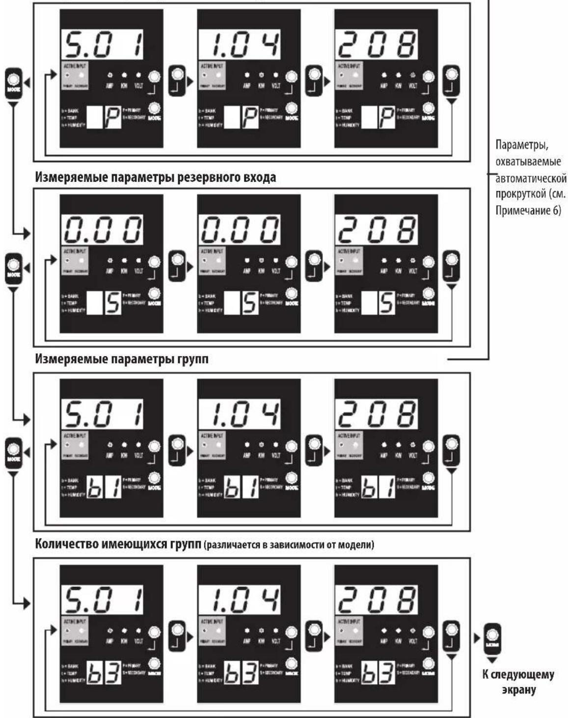
PnmeH 1. npepexoBa CneDyoum peKMM OTobpaKeHHB (septHKaJIbHOe nepeMeueHHe no daHHOMy DOkymEHT) HAKMTE KONKY Mode. CnDyET MmEB B BND, TTO npDpKMM AmpS, KW mN VolcXPAAHETCA B NAMTN.
PmpeHne 2. Dnepexoda B cndyuynn no npdeKHM oTobpaenHH (ropm30HTabHoe nepeMeHne No daHHMy dokmy H) hAnMTe KhONky Enter.
PmepaHne 3. CBeTodHbHe HINKATOpbI AKTHBHO BxOda BCERda Yka3BaIK HA TcOHTHK, NtAIOUHN HAPy3Kb DAnHHb MoMeHNT. (Bo BcEx h06paeKHeBb Buae npmeAp xpeDnONaRaTeC, 100 BpaHbN B aHHM MoHENT HCTOCHK HBAETCA OCHOBHMM. CnEyt IMeTb B bHy, ToB CnyuAe BbOopa peseBHO HcTOCHHKa Bgyet roptb cooBETCTByouHm Emy Cd, aCd, cooBETCTByouHm OCHOBHOMY ITOCHNK, Ropet He ByqEt ECnn Hs ONDH HcTOCHNKOB He pRtoDEH ndy FHKUHNHOPOBAHNN, To 6ba CbeTODHbX MInKAtopo (cooBETCTBYOUHc OCHOBHOMY npePBHO MyOTOHKHAM) octOaTOB BbKIOHBBHM.
PmmeHne 4. nto o6paekhen IP-anaepnoNkKueHHn SNMP-kapTbO zoHNbpeMeHHNo HAKMnte KhoNNK mode HEnter uyepkhaaiTe Hx b teueHne 2 cekyHd.
PmmeHne 5. npeeknuehen B pckmby npaebnna (Contol) hakmtte knonky MODE H yepkmaai te e b teehme 2 ckyh (B peynbtae tto ory tpo nepejnt B PEPbbm pekmym npaebnna).
PnmeaHne 6. nBknoeHHo yHKnH ABOTAMuecko npokpyKra (Auro Scoll) noce 10 cekyH 63edCTbna dactnny beDyt HnpepebHO nepeKNHm ToKa,MOIOHCHN HnpankeHn HA OCHOBM BXOe HANALINHMM NOK3AHMRn HA pe3epBH MxOe CnncFyKuMM B03BPaTOM K TOKY HA OCHOBM BXOe.
Cxembl paCnoIoxKeHnBcBeToDnOndbIX INHnKaTopoB
Pekmbi oTo6paxeHn
Pexm oTo6paKeHHaTeMnpeaTpby (OocTyneH TOnbK npn noKnouenHom yctpoiCTbe EnviroSense)
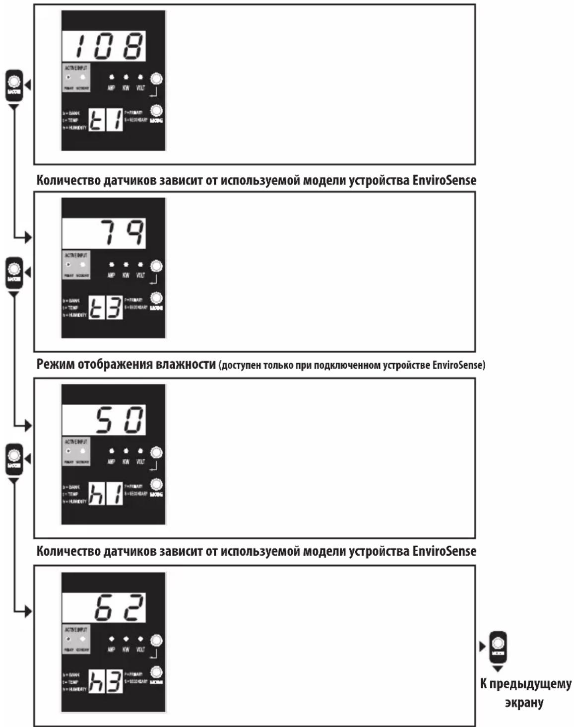
PnmeHne 1. nepexoDa B cnyuonpexHM OTObpaKeHMa (BepTKaJIbHOe nepeMeueHne no daHHOMy DOKMyHTy) HAKMITE KONKY Mode. Cnyet HmETb B BVdy, TOnpeKMM Amps, kW mVolt coxpaneta B naTn.
Pnme Hne 2. npepeoxa B cneynooh nopekno OTO6paeknna (ropnohtanbhoe nepeemeeHne no daHNOHY KOmyh) hAKMTKe KHOky Enter.
PnmeHne 3. CbeTdoHIOhBle IHNkAToBpI aKTHBHO BxOda BCerDa yKa3bIbAOT Ha ITOCHNK, NITaIOHN HAry3yB DAHHB MoMeHT.
PnmeaHne 4. IOn oTo6paKeHHN IP-aDpeca noKnKIOueHHo SNMP-KapTb oNoHOBpeMeHHo HAKMHe KOHN Mode n Enter n ydEpkBaTe Hx B TeueHne 2 cekyHn.
PnmeHne 5. npeKnoe H B pkmbl npabne Hna Kmtte KOnky MODE u npkbae ee b teehne 2 ckynd. (B peyntate toro yctpoictbo neepd E PEPbI pekm npabne H