
Genius G4 - Battery charger NOCO - Free user manual and instructions
Find the device manual for free Genius G4 NOCO in PDF.
| Product Type | 8-Step Smart Battery Charger |
| Brand | NOCO |
| Model | Genius G4 |
| Number of Charging Bases | 4 |
| Input Voltage | 220-240 V, 50-60 Hz |
| Maximum Power | 84 W |
| Charging Current per Base | 1.1 A (12 V or 6 V) |
| Total Current | 4.4 A |
| Charging Voltage | Variable according to mode (7.25 V to 14.8 V) |
| Compatible Battery Types | Lead-acid (wet, gel, MF, CA, EFB, AGM) and lithium-ion (12V) |
| Battery Capacity (Charge) | 2 to 40 Ah |
| Battery Capacity (Maintenance) | All sizes |
| Charging Modes | Standby, Normal 12V, Cold/AGM 12V, Normal 6V, Lithium 12V |
| Safety Functions | Reverse polarity protection, spark-proof, overcharge, overcurrent, undervoltage, overheat |
| LED Indicators | 4 progress LEDs (25%, 50%, 75%, 100%) and standby/error LED |
| Advanced Diagnostics | Reverse polarity detection, low voltage battery, defective battery |
| Protection Rating | IP64 (dust and splash resistant) |
| Dimensions (L x W x H) | 283 x 280 x 72 mm |
| Weight | 1.286 kg |
| Wall Mount | Yes, via 4 mounting eyelets |
| Included Accessories | 2 HD clamps, 2 eyelet connectors, 4 extension cables, user manual |
| Warranty | Refer to the provided warranty guide |
| Maintenance | No special maintenance required; clean with a dry cloth |
| Repairability | Spare parts not specified; contact NOCO support |
Frequently Asked Questions - Genius G4 NOCO
User questions about Genius G4 NOCO
0 question about this device. Answer the ones you know or ask your own.
Ask a new question about this device
Download the instructions for your Battery charger in PDF format for free! Find your manual Genius G4 - NOCO and take your electronic device back in hand. On this page are published all the documents necessary for the use of your device. Genius G4 by NOCO.
USER MANUAL Genius G4 NOCO
PRIOR TO USE, READ AND UNDERSTAND PRODUCT SAFETY INFORMATION. Failure to follow the instructions may result in ELECTRICAL SHOCK, EXPLOSION, or FIRE, which may result in SERIOUS INJURY, DEATH, DAMAGE TO DEVICE or PROPERTY. Do not discard this information.
Welcome. Thank you for buying the NOCO Genius® G4. Read and understand the User Guide before operating the charger. For questions regarding our chargers, view our comprehensive support information at www.no.co/support. To contact NOCO for personalized support (not available in all areas), visit www.no.co/connect.
What's In The Box.
G4 4-Bank Smart Charger
(2) Battery Clamp Connectors
(2) Eyelet Terminal Connectors
(4) Extension Cables
- User Guide
Information Guide and Warranty
Contacting NOCO.
Phone: 1.800.456.6626
Email: support@no.co
Mailing Address: 30339 Diamond Parkway, #102
Glenwillow, OH 44139
United States of America
About G4. The NOCO Genius® G4 represents some of the most innovative and advanced technology on the market, making each charge simple and easy. It is quite possibly the safest and most efficient charger you will ever use. The G4 is designed for charging multiple (up to 4) 12V lead-acid and 12V lithium-ion batteries, including Wet (Flooded), Gel, MF (Maintenance-Free), CA (Calcium), EFB (Enhanced Flooded Battery), AGM (Absorption Glass Mat), and LIB (Lithium-Ion) batteries. It is suitable for charging battery capacities from 2 to 40 Amp-Hours and maintaining all battery sizes.
Getting Started. Before using the charger, carefully read the battery manufacturer's specific precautions and recommended rates of charge for the battery. Make sure to determine the voltage and chemistry of the battery by referring to your battery owner's manual prior to charging.
Mounting. The G4 has four (4) external holes for mounting. Mount the charger in a desired location with #6 self-drill screws. Make sure there are no obstructions behind the mounting surface. It is important to keep in mind the distance to the battery. The lengths of the DC cable from the charger, with either the battery clamp or eyelet terminal connectors, is approximately 142-inches (3600mm).
Charging Modes. The G4 has five (5) modes per bank: Standby, 12V NORM, 12V COLD/AGM, 6V NORM, and 12V LITHIUM. Some charge modes must be pressed and held for three (3) seconds to enter the mode. These "Press and Hold" modes are advanced charging modes
that require your full attention before selecting. "Press and Hold" are indicated on the charger by a red line. It is important to understand the differences and purpose of each charge mode. Do not operate the charger until you confirm the appropriate charge mode for your battery. Below is a brief description:
| Mode Explanation | |
| Standby | In Standby mode, the charger is not charging or providing any power to the battery. Energy Save is activated during this mode, drawing microscopic power from the electrical outlet. When selected, an orange LED will illuminate. No Power |
| 12V NORM | For charging 12-volt Wet Cell, Gel Cell, Enhanced Flooded, Maintenance-Free and Calcium batteries. When selected, a white LED will illuminate. 14.5V | 1.1A | 2-40Ah Batteries |
| 12V COLD/ AGM | For charging 12-volt batteries in cold temperatures below 50°F (10°C) or AGM batteries. When selected, a blue LED will illuminate. 14.8V | 1.1A | 2-40Ah Batteries |
| 6V NORM | For charging 6-volt Wet Cell, Gel Cell, Enhanced Flooded, Maintenance-Free and Calcium batteries. When selected, a white LED will illuminate. 7.25V | 1.1A | 2-40Ah Batteries |
| 12V LITHIUM | For charging 12-volt lithium-ion batteries, including lithium iron phosphate. When selected, a blue LED will illuminate. 14.2V | 1.1A | 2-40Ah Batteries |
Using 6V NORM. [Press & Hold]
6V NORM charge mode is designed for 6-volt lead-acid batteries only, like Wet Cell, Gel Cell, Enhanced Flooded, Maintenance-Free and Calcium batteries. Consult the battery manufacturer before using this mode.
CAUTION. THIS MODE IS FOR 6-VOLT LEAD-ACID BATTERIES ONLY.
Using 12V Lithium. [Press & Hold]
12V Lithium charge mode is designed for 12-volt lithium-ion batteries only, including lithium iron phosphate.
CAUTION. USE THIS MODE WITH CARE. THIS MODE IS FOR 12-VOLT LITHIUM BATTERIES ONLY. LITHIUM-ION BATTERIES ARE MADE AND CONSTRUCTED IN DIFFERENT WAYS AND SOME MAY OR MAY NOT CONTAIN A BATTERY MANAGEMENT SYSTEM (BMS). CONSULT THE LITHIUM BATTERY MANUFACTURER BEFORE CHARGING AND ASK FOR RECOMMENDED CHARGING RATES AND VOLTAGES. SOME LITHIUM-ION BATTERIES MAY BE UNSTABLE AND UNSUITABLE FOR CHARGING. MAKE SURE YOU PURCHASE YOUR LITHIUM-ION BATTERY FROM A WELL-KNOWN AND REPUTABLE BRAND.
Connecting to the Battery.
Do not connect the AC power plug until all other connections are made. Identify the correct polarity of the battery terminals on the battery. The positive battery terminal is typically marked by these letters or symbol (POS,P,+) . The negative battery terminal is typically marked by these letters or symbol (NEG,N,-). Do not make any connections to the carburetor, fuel lines, or thin, sheet metal parts. The below instructions are for a negative ground system (most common). If your vehicle is a positive ground system (very uncommon), follow the below instructions in reverse order.
1.) Connect the positive (red) battery clamp or eyelet terminal connector to the positive (POS,P,+ ) battery terminal.
2.) Connect the negative (black) battery clamp or eyelet terminal connector to the negative (NEG,N,-) battery terminal or vehicle chassis.
3.) Connect the battery charger's AC power plug into a suitable electrical outlet. Do not face the battery when making this connection.
4.) When disconnecting the battery charger, disconnect in the reverse sequence, removing the negative first (or positive first for positive ground systems).
Begin Charging.
1.) Verify the voltage and chemistry of the battery.
2.) Confirm that you have connected the battery clamps or eyelet terminal connectors properly and the AC power plug is plugged into an electrical outlet.
3.) The charger will begin in Standby mode, indicated by an orange LED. In Standby, the charger is not providing any power.
4.) Press the mode button to toggle to the appropriate charge mode (press and hold for three seconds to enter an advanced charge mode) for the voltage and chemistry of your battery.
5.) The mode LED will illuminate the selected charge mode and the Charge LEDs will illuminate (depending on the health of the battery) indicating the charging process has started.
6.) The charger can now be left connected to the battery at all times to provide maintenance charging.
Understanding Charge LEDs.
The charger has four (4) Charge LEDs per bank - 25% , 50% , 75% and 100% . These Charge LEDs indicate the connected battery(s) state-of-charge (SOC). See the explanation below:
| LED Explanation | |
| 25% Red LED 25% 50% 75% 100% ●○○○ | The 25% Charge LED will slowly pulse “on” and “off”, when the battery is less than 25% fully charged. When the battery is 25% charged, the red Charge LED will be solid. |
| 50% Red LED 25% 50% 75% 100% ●○○○ | The 50% Charge LED will slowly pulse “on” and “off”, when the battery is less than 50% fully charged. When the battery is 50% charged, the red Charge LED will be solid. |
| 75% Orange LED 25% 50% 75% 100% ●○○○ | The 75% Charge LED will slowly pulse “on” and “off”, when the battery is less than 75% fully charged. When the battery is 75% charged, the orange Charge LED will be solid. |
| 100% Green LED 25% 50% 75% 100% ○○○○ | The 100% Charge LED will slowly pulse “on” and “off”, when the battery is less than 100% fully charged. When the battery is fully charged, the green LED will be solid, and the 25%, 50% and 75% Charge LEDs will turn “off”. |
| Maintenance Green LED 25% 50% 75% 100% ○○○○ | During maintenance charging, the 100% Charge LED will pulse “on” and “off” slowly. When the battery is topped off and fully charged again, the 100% Charge LED will turn solid green. The charger can be left connected to the battery indefinitely. |
Understanding Advanced Diagnostics.
Advanced Diagnostics is used when displaying Error Conditions. It will display a series of blink sequences that help you identify the cause of the error and potential solutions.
All Error Conditions are displayed with the Error LED and Standby LED flashing back and forth. The number of flashes between each pulse denotes a potential Error Condition (except reverse polarity and low-voltage battery).
| Error Reason/Solution | |
| Single Flash | Battery will not hold a charge. Have battery checked by a professional. |
| Double Flash | Possible battery short. Have battery checked by a professional. |
| Triple Flash | Battery voltage is too high for the selected charge mode. Check the battery and charge mode. |
| Error LED Solid Red | Reverse polarity. Reverse the battery connections. |
| Standby Solid Orange | Battery voltage is too low for charge to detect or charger is in supply. Jumpstart the battery to raise the battery voltage. |
Memory
Returns to last selected mode when restarted

Interactive
Alters the charging process based on organic battery feedback

Recovery
Applies a high-voltage pulse charge when low-voltage, sulfation or lost capacity is detected

Safe
Protects against reverse polarity, sparks, overcharging, overcurrent, open-circuits, short-circuits and overheating

Fast
Charges two times faster than traditional battery chargers
Compensation
Adjusts for varying A/C line voltage for consistent charging

Rugged
Dirt, water, UV, impact and crush resistant

Compact
High-frequency energy conversion for ultra-compact, lightweight and portable charger

Start-Stop
Counteracts increased cyclic energy demands placed on batteries in micro-hybrid vehicles

Firewall
Multi-level safety barrier that prevents abnormal and unsafe conditions

Optimization
Stabilizes internal battery chemistry for increased performance and longevity


Maintenance Plus
Keeps the battery fully charged without overcharging allowing the charger to be safely connected indefinitely

Energy Save
Minimizes energy consumption when full power is not needed

Load Tracking
Charge LEDs dynamically track the batteries state-of-charge when a load outpaces the charge current

Diagnostics
Intuitive visual diagnostic tool for detecting reverse polarity, low-voltage or damaged batteries

CANBUS
Automatically enables the charging port to charge CANBUS systems

Thermal Monitor
Internal temperature sensors adjust charge based on ambient climate
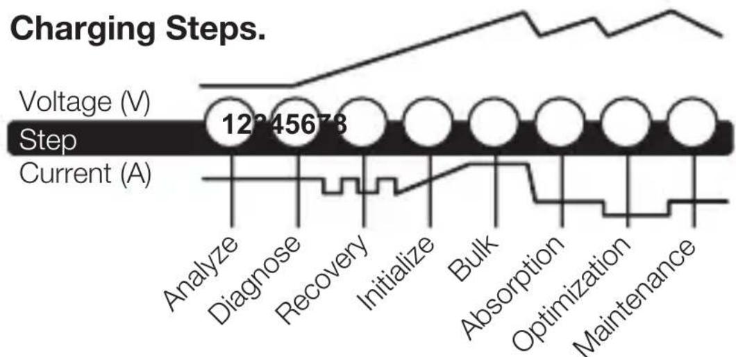
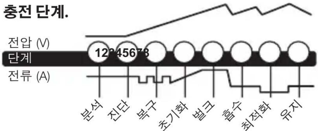
Step 1 & 2: Analyze & Diagnose
Checks the battery's initial condition, including voltage, state-of-charge and health, to determine if the battery is stable before charging.
Step 3:Recovery
Initializes the Recovery desulfation process (if needed) for deeply discharged or sulfated batteries by pulsing small amounts of current.
Step 4: Initialize
Starts the charging process with a gentle (soft) charge.
Step 5: Bulk
Begins the Bulk charging process based on the condition of the battery and returns 80% of the battery's capacity.
Step 6: Absorption
Brings the charge level to 90% by delivering small amounts of current to provide a safe, efficient charge. This limits battery gassing and is essential to prolonging battery life.
Step 7: Optimization
Finalizes the charging process and brings the battery to maximum capacity. In this step, the charger utilizes multi-layered charging profiles to fully recapture capacity and optimize the specific gravity of the battery for increased run time and performance. The charger will switch to Maintenance if the battery tells the charger that more current is needed.
Step 8: Maintenance
Continuously monitors the battery to determine when a maintenance charge should be initiated. If the battery voltage falls below its target threshold, the charger will restart the Maintenance cycle until voltage reaches its optimal state and then discontinues the charge cycle. The cycle between Optimization and Maintenance is repeated indefinitely to keep the battery at full charge. The battery charger can be safely left connected indefinitely without the risk of overcharging.
Charging Times.
The estimated time to charge a battery is shown below. The size of the battery (Ah) and its depth of discharge (DOD) greatly affect its charging time. The charge time is based on an average depth of discharge to a fully charged battery and is for reference purposes only. Actual data may differ due to battery conditions. The time to charge a normally discharged battery is based on a 50% DOD.
| Battery Size Approx. Time to Charge In Hours 6V 12VAh | ||
| 8 | 3.6 | 3.6 |
| 12 | 5.5 | 5.5 |
| 18 | 8.2 | 8.2 |
| 24 | 10.9 | 10.9 |
| 40 | 18.2 | 18.2 |
Technical Specifications.
| Input Voltage AC: | 220-240, 50-60Hz |
| Working Voltage AC: | 220-240, 50-60Hz |
| Efficiency: | 85% Approx. |
| Power: | 84W Max |
| Charging Voltage: | Various |
| Number of Banks: | 4 |
| Charging Current: | 4.4A/1.1A per Bank (12V), 4.4A/1.1A per Bank (6V) |
| Low-Voltage Detection: | 2V (12V), 2V (6V) |
| Back Current Drain: | <5mA |
| Ambient Temperature: | 0°C to +40°C |
| Charger Type: | 8 Step, Smart Charger |
| Type of Batteries: | 6V & 12V |
| Battery Chemistries: | Wet, Gel, MF, CA, EFB, AGM & LIB |
| Battery Capacity: | 2-40Ah (12V), 2-40Ah (6V), Maintains All Battery Sizes |
| Housing Protection: | IP64 |
| Cooling: | Natural Convection |
| Dimensions (L x W x H): | 11.15 x 11 x 2.83 Inches |
| Weight: | 2.78 Pounds |
French
NOCO EU genius
G4 v2.0
Specifications techniques.
United States of America
United States of America
United States of America
OG4.NOCO Genius G4 npedctablaet HeKOtOpbIe n3 cambIX INHHOBaCNOHHbIX INpepEOBbIX TexHOJOrn Ha pbIHke,JeJa KaKdbI npocecc 3apAkn npOSe n ydo6Hee. 3TO 3apAHDoe yCTPOiCTBO,BNOLHe BO3MOXHO,ABJIeTcH Han6OJIee 6e3OpaCHbIM N OphiEKTNBbIM n3Tex,yTO Bam npiDETcNcOJIb3OBAtB.G4 npedHa3NaUeH OJIa 3apAkn HeCKoJIbKnx (do 4)12V CBINHCIOBO-KNCLOTHbIX n 12V JNTNI-HOHNbIX aKKyMnyIaTOPOB,BKIIoua KNCLOTHbIE,TeJIeBbIE,MF (Heo6cIyKInBaemble),CA (KaJIbUeBbie),EFB (ycJIeHbIE KNCLOTHbIE),AGM (cnPONHTAHbIMn CTeKIOBaTHbIMn MaTAm),and LFP (nITn-JKeJe3o-ΦocΦaTHbIe) aKKymyIaTOPbl. PoIxODnT dJa 3apAkn aKKyMnyIaTOPOB EMKoCTbIO OT 2 do 40 amneP-uaCoB n NOdEepxNBAe T BCE pa3MepbI aKKymyIaTOPOB.
Hauano pa60tbl. Npeed 3Kcnpyaataunei 3apndno yctpoiCTBa BHIMaTeIbHO npOHTte CpeuaJIbHbIe Mepbl npeIOCTOPOXHOCTN, COCTaBHeHHbIe PpON3BOIDNTeIem aKKymyIaTopa i peKOMeHNdyEmyU BELnHy TOka 3apra. O6a3aTeIbHO onpeDeInte HnprJKeHne i xmMueckn coCTab aKKymyIaTopa, n3yUnB nepeD 3apdKO INHCTpyKcuHIO NO 3KcnpyaTaun.
MOHTaK. G4 nMeet yeTbIpe (4) BHeuHnX OTBepCTnJa MOHTaKa. YcTaHOBInTe 3apAINHOe yCTPOINCTBO B HUxHOM MeCTe C NOMOUsIO CAMOCBepJIaNIX BNHTOB #6. U6eINTEcB BVOTCYTCTBn IN PpeIATCTBn I03aIN MOHTaXHOJ NOBepXHOCTN. BaXHo nMeTb B BVNDy pAcSToHNHe Do aKKymyTATopa. DInHa DC-Ka6eJIA 3apAINHOrO yCTPOINCTBa, OChaIeHHORO CoeINHITeJIem C 3aXIMOM INI KJIeMMOn-IPoYShINOH, COCTABJAEr 142 JIOIma (360).
Pexmbl 3apdkn. G4 nMeet 5 (5) pexmOB ha 6noK. Standby, 12V NORM, 12V COLD/AGM, 6V NORM n 12V LITHIUM. IJIa HeKOToBix peXmOB 3apdkn Heo6xOIMo HaxaTb u YdepxkBaTb (3) cekyHdbI DnBxAODa B peXm. DaHHbIe pexmbl "HaxaTb n UdepXkBaTb" ABJOTc paCShupeHHbIMn peXmAmn 3apdkn, KOTOpbIe Tpe6yIOT BaWeRo NOHOrO BHImaHn IpeE Bb6Opom. Pexmbl "HaxaTb n YdepxkBaTb" OTMeueHbI Ha 3apAnHom yCTpoiCTBe KpaCHO nnHe.BaxHO noHMaTb pa3nnuYn Ha3NaueHne KaJdOro peXmMa 3apdkn. He nCpOnb3yIte 3apJdHoe yCTPOICTBO, noka He npOBepUTe, kaKoI peXmЯBJIeTCr NOxOJaum m dIra BaWeero aKKymyIaTopa. Hxke npIBOHTc KpaTKOE ONscAHne.
IprimeHreT 3apd BbICOKOHa npJxKeHn npo6hApJxKeHn HN3KOro Ha npJxKeHn, cyIbphiu nn yTpate EMKocTn

Be30nacHocTb
IpedoxpaHaret ObpaTHoN pOJIrpHOCTn,
NcKp, nepe3apdKn, nepeHaPpJKeHnA,
pa3MbikAHnA ceni, KOPOTKOrO 3aMbikAHnA n
neperpeBa

CkopoocTb
3apjkaetBДBa pa3a 6bICTpee,чem O6bIuHbIe 3apJNbIe yCTpOiCTBa
ypaBHOBeWNBaHne
HactpaINBaETcHa HanpJxKeHne cetn nepemehHO TOKa dJa HepepbIBHOJ 3apJDKI

HadëxHoCTb
YCTOINBOCTb K DaBJIeHIO IN BIIJHHIO rpa3N, BOJe, YΦ

KOMNaKTHOCTb
Преобразоваиме заергиги Высокою частotыдля ульста-KOMпakTHORO,лergковесноги NOPTaTNBHORO 3apdHORO yctpoiCTBa

CtapT-Cton
IpoTnBOeJCTByeT NOBbIWeHIO ZIKNHyHOrO nOTpe6JIeHnEHePnI pRn NOMEeHnHa Mnkporn6pndHbIe aBTOMo6nIi


Cnctema 3aunTbI
MhoroypOBHeBbI 3aunTHbI 6apbep,
npedOTBpaauoHn HeTnHbIe n
He6e3OpacHbIe ycIOBnA
Оптимиаця
Ct6nI3npyeT BHyTpEHHN XmMueckn COCTaB 6aTapen IJyYBeJIuYeHn IpOIN3BOAnTeNbHOCTn I DOJROBeUHOCTn

TexHnuecka npoΦnlaKtɪka ПлUC
ДержИТ aKKуMЛЯТОР NOJIHOCbI O 3apJxKeHHbIM 6e3 nepe3apJxKeHHOCTN, NO3BOJRA NOCTOJHHO DePkaTb 3apJdHoe yCTpoIcTBO NOkJIIOUeHHbIM
эковомияэнергий
Chnkaet notpe6leHne 3Heprn, KOrda He Tpe6yeTcI NOHaM OoHocTb

OtceKnBaHne Harpy3Kn
CBeToIIOHbIe INHdNkAToPbI 3apra Da INHaMnUHOOTcIeXnBaIoT COCTOaHne 3apra 6aTapei, KOrda Harpy3Ka OIepexkaeT TOK 3apra

Диагностка
HHTyNTBHyBn Bn3yaJIbHO-DnaTHOCTnueckn HNCTpyMeHT dIa O6HapUxKeHnO 6paTHo NOLpHOCTn, HN3KOrO HaPjXeHnI NII NOBpeJdEHHo 6aTapen.

CANBUS
AByOMaTnueckn BKnIouaet 3apAnhbl NOpT dJa 3apAnkCnCTem CANBUS

United States of America
Stap 4: Initialising
E-post: support@no.co
E-postaddress: 30339 Diamond Parkway, #102
Glenwillow, OH 44139
United States of America
Om G4. NOCO Genius® G4 stared for en del av
United States of America
囧連華士歌則樂,樂樂樂樂樂樂樂樂樂樂樂樂樂樂樂樂樂樂樂樂樂樂樂樂樂樂樂樂樂樂樂樂樂樂樂樂樂樂樂樂樂樂樂樂樂樂樂樂
用龍到青頭及多在賊托利克目用之,
.
新庄章的,
摺止希SIMSiO.賄TREiSAUgSfMgRrtoe
前日和会学的在到定,
喜 .G4是当的同
在合n#.#6插-三列n#a#是的,
喜
默在山。
中要。
KerckTe)epfDCKeIeJtJiJiJ142in
(3600mm) 儿に。
喜連目. G4は必克マド多(5)の必地が
Moto to be able to "Press and Hold" MoTs are the
“Press
and Hold"是曾关”系以或置真,
MoTr的iT和默t成i
| LED | SEL명 |
| 25% 출gan식 LED 25% 50% 75% 100% ●○○○ | 버terri가 25% 이하로 출전해 겨울, 25% Charge LED는 전쟁이 “>c고,”“>c고,” 贓목"을 Back복 ,(버terri가 25% Prior returned, 출gan식 Charge LED에 개수 기재 퍻이 썻목nio. |
| 50% 출gan식 LED 25% 50% 75% 100% ●○○○ | 버terri가 50% 이하로 출전해 겨울, 50% Charge LED는 전쟁이 “>c고,”“>c고,” 贓목"을 Back복 ,(버terri가 50% Prior returned, 출gan식 Charge LED에 개수 기재 퍻이 썻목nio. |
| 75% nb라ERIC LED 25% 50% 75% 100% ●○○○ | 버terri가 75% 이하로 출전해 겨울, 75% Charge LED는 전쟁이 “>c고,”“>c고,” 贓목"을 Back복 ,(버terri가 75% Prior returned, nbraRIC Charge LED에 개수 기재 퍻이 썻목nio. |
| 100% 출抢单 LED 25% 50% 75% 100% ○○○● | 버terri가 100% 이하로 출전해 겨울, 100% Charge LED는 전쟁이 “>c고,”“>c고,” 贓목"을 Back복 ,(버terri가 100% Prior returned, nbraRIC Charge LED에 개수 기재 퍻이 썻목nio. |
| 유지 Prioracock LED 25% 50% 75% 100% ○○○● | 유지 출전道路上,(100% Charge LED는 전쟁이 “>c고,”“>c고,” 贓목"을 Back복 ,(버terri가 100% Prior returned, before returning to the park. Charge LED에 친고 퍻이 썻목nio. Prior returned, before returning to the park. Charge LED에 친고 퍻이 썻목nio. Prior returned, before returning to the park. Charge LED에 친고 퍻이 썻목nio. Prior returned, before returning to the park. Prior returned, before returning to the park. Prior returned, before returning to the park. Prior returned, before returning to the park. Prior returned, before returning to the park. Prior returned, before returning to the park. Prior returned, before returning to the park. Prior returned, before returning to the park. Prior returned, before returning to the park. Prior returned, before returning to the park. Prior returned, before returning to the park. Prior returned, before returning to the park Prior returned, before returning to the park. Prior returned, before returning to the park. Prior returned, before returning to the park. Prior returned, before returning to the park. Prior returned, before returning to the park. Prior returned, before returning to the park. Prior returned, before returning to the park. Prior returned, before returning to the park. Prior returned, before returning to the park. Prior returned, before returning to the park. Prior returned, before returning to the park. Prior returned, before returning to the park. Prior returned, before returning to the park. Prior returned, before returning to the park. Prior returned, before returning to the park. Prior returned, before returning to the park. Prior returned, before returning to the park. Prior returned, before returning to the park. Prior returned, before returning to the park. Prior returned, before returning to the park. Prior returned, before returning to the park. Prior returned, before returning to the park. Priorreturned, before returning to the park. Prior returned, before returning to the park. Prior returned, before returning to the park. Prior returned, before returning to the park. Prior returned, before returning to the park. Prior returned, before returning to the park. Prior returned, before returning to the park. Prior returned, before returning to the park. Prior returned, before returning to the park. Prior returned, before returning to the park. Prior returned, before returning to the park. Prior returned, Prior returned, before returning to the park. Prior returned, before returning to the park. Prior returned, before returning to the park. Prior returned, before returning to the park. Prior returned, before returning to the park. Prior returned, before returning to the park. Prior returned, before returning to the park. Prior returned, before returning to the park. Prior returned, before returning to the park. Prior returned, before returning to the park. Prior returned, before returning to the park. prior returned, before returning to the park. Prior returned, before returning to the park. Prior returned, before returning to the park. Prior returned, before returning to the park. Prior returned, before returning to the park. Prior returned, before returning to the park. Prior returned, before returning to the park. Prior returned, before returning to the park. Prior returned, before returning to the park. Prior returned, before returning to the park. Prior returned, before returning to the park. Prior responded, before returning to the park. Prior responded, before returning to the park. Prior responded, before returning to the park. Prior responded, before returning to the park. Prior responded, before returning to the park. Prior responded, before returning to the park. Prior responded, before returning to the park. Prior responded, before returning to the park. Prior responded, before returning to the park. Prior responded, before returning to the park. Prior responded, before returning to the park. Prior responded, Prior responded, before returning to the park. Prior responded, before returning to the park. Prior responded, before returning to the park. Prior responded, before returning to the park. Prior responded, before returning to the park. Prior responded, before returning to the park. Prior responded, before returning to the park. Prior responded, before returning to the park. Prior responded, before returning to the park. Prior responded, before returning to the park. Prior responded, before returning to the park. prior responded, before returning to the park. Prior responded, before returning to the park. Prior responded, before returning to the park. Prior responded, before returning to the park. Prior responded, before returning to the park. Prior responded, before returning to the park. Prior responded, before returning to the park. Prior responded, before returning to the park. Prior responded, before returning to the park. Prior responded, before returning to the park. Prior responded, before returning to the park. Prior responding, before returning to the park. Prior responded, before returning to the park. Prior responded, before returning to the park. Prior responded, before returning to the park. Prior responded, before returning to the park. Prior responded, before returning to the park. Prior responded, before returning to the park. Prior responded, before returning to the park. Prior responded, before returning to the park. Prior responded, before returning to the park. Prior responded, before returning to the park. Prior responded. before returning to the park. Prior responded, before returning to the park. Prior responded, before returning to the park. Prior responded, before returning to the park. Prior responded, before returning to the park. Prior responded, before returning to the park. Prior responded, before returning to the park. Prior responded, before returning to the park. Prior responded, before returning to the park. Prior responded, before returning to the park. Prior responded, before returning to the park. Prior responded, Before returning to the park. Prior responded, before returning to the park. Prior responded, before returning to the park. Prior responded, before returning to the park. Prior responded, before returning to the park. Prior responded, before returning to the park. Prior responded, before returning to the park. Prior responded, before returning to the park. Prior responded, before returning to the park. Prior responded, before returning to the park. Prior responded, before returning to the park. Prior responded, before Prior responded, before returning to the park. Prior responded, before returning to the park. Prior responded, before returning to the park. Prior responded, before returning to the park. Prior responded, before returning to the park. Prior responded, before returning to the park. Prior responded, before returning to the park. Prior responded, before returning to the park. Prior responded, before returning to the park. Prior responded, before returning to the park. Prior responded, before returning to the park. Prior responded, before returning to the park. Prior responded, before returning to the park. Prior responded, before returning to the park. Prior responded, before returning to the park. Prior responded, before returning to the park. Prior responded, before returning to the park. Prior responded, before returning to the park. Prior responded, before returning to the park. Prior responded, before returning to the park. Prior responded, before returning to the park. Prior responded, before returning to the park. Prior responds, before returning to the park. Prior responded, before returning to the park. Prior responded, before returning to the park. Prior responded, before returning to the park. Prior responded, before returning to the park. Prior responded, before returning to the park. Prior responded, before returning to the park. Prior responded, before returning to the park. Prior responded, before returning to the park. Prior responded, before returning to the park. Prior responded, before returning to the park. Prior responded. Prior responded. Prior responded. Prior responded. Prior responded. Prior responded. Prior responded. Prior responded. Prior responded. Prior responded. Prior responded. Prior responded. Prior responded. Prior responded. Prior responded. Prior responded. Prior responded. Prior responded. Prior responded. Prior responded. Prior responded. Prior responded. Prior responded. Prior responded. Prior responded. Prior responded. Prior responded. Prior responded. Prior responded. Prior responded. Prior responded. Prior responded. Prior responded. Prior responded Prior responded Prior responded Prior responded Prior responded Prior responded Prior responded Prior responded Prior responded Prior responded Prior responded Prior responded Prior responded Prior responded Prior responded Prior responded Prior responded Prior responded Prior responded Prior responded Prior responded Prior responded Prior responded Prior responded Prior responded Prior responded Prior responded Prior responded Prior responded Prior responded Prior responded Prior responded Prior responded Prior responded prior responded Prior responded Prior responded Prior responded Prior responded Prior responded Prior responded Prior responded Prior responded Prior responded Prior responded Prior responded Prior responded Prior responded Prior responded Prior responded Prior responded Prior responded Prior responded Prior responded Prior responded Prior responded Prior responded Prior responded Prior responded Prior responded Prior responded Prior responded Prior responded Prior responded Prior responded Prior responded Prior responded Prior respond Prior responded Prior responded Prior responded Prior responded Prior responded Prior responded Prior responded Prior responded Prior responded Prior responded Prior responded Prior responded Prior responded Prior responded Prior responded Prior responded Prior responded Prior responded Prior responded Prior responded Prior responded Prior responded Prior responded Prior responded Prior responded Prior responded Prior responded Prior responded Prior responded Prior responded Prior responded Prior responded Prior responded |
高同
龍龍龍龍龍龍龍龍龍龍龍龍龍龍龍龍龍龍龍龍龍龍龍龍龍龍龍龍龍龍龍龍龍龍龍龍
海事

用
请前加安前加用的
在目录, 和增前嵌在映射器的映射中。
俱大
社比

豆三
把h加中进平到用
動態の上部部を翻圧操作起来。

默国,,是
釜志如能,自古之机。

CANBUS(客户端)
自動に用 CANBUS 信道を連続する
请前托

日
내부운드선서가 출본운드에 힍선을
J

☑ 1.2: 2
[BaTRE] the state of the art, a new technology that is rapidly becoming popular in the market.
##
J 1 J 1 J 1 J 1 J 1 J 1 J 1 J 1 J 1 J 1 J 1 J 1 J 1 J 1 J 1 J 1 J 1 J 1 J 1 J 1 J 1 J 1 J 1 J 1 J 1 J 1 J 1 J 1 J 1 J 1 J 1 J 1 J 1 J 1 J
J 1 J 1 J 1 J 1 J 1 J 1 J 1 J 1 J 1 J 1 J 1 J 1 J 1 J 1 J 1 J 1 J 1 J 1 J 1 J 1 J 1 J 1 J 1 J 1 J 1 J 1 J 1 J 1 J 1 J 1 J 1 J 1 J 1 J 1
3 3
J 1 J 1 J 1 J 1 J 1 J 1 J 1 J 1 J 1 J 1 J 1 J 1 J 1 J 1 J 1 J 1 J 1 J 1 J 1 J 1 J 1 J 1 J 1 J 1 J 1 J 1 J 1 J 1 J 1 J 1 J 1 J 1 J 1 J 1 J
4
.()
5 5
80% aas nss gaaaal llae snae 5 aee 1n nn aaan
yolai:6gbl
J 90% a s Jn Jn Jn Jn Jn Jn Jn Jn Jn Jn Jn Jn Jn Jn Jn Jn Jn Jn Jn Jn Jn Jn Jn Jn Jn Jn Jn Jn Jn Jn Jn Jn Jn Jn Jn Jn Jn Jn Jn Jn Jn
JIOI JI JI JI JIJI:7Og
0 1 1 1 1 1 1 1 1 1 1 1 1 1 1 1 1 1 1 1 1 1 1 1 1 1 1 1 1 1 1 1 1 1 1 1 1 1 1 1 1
Joo
Lg 1yBbU AaI UaI yIyIyIyIyIyIyIyIyIyIyIyIyIyIyIy
aoloylaol

.0sgaao aaw gaiy5 gai
S OAB = S COD + S_ BDO
Jg jj g Jg Jg Jg Jg Jg Jg
.


2010
.
a g 1g x b y
gag
.
S|U|b|U|
g g g g g g g g g g g g g g g g g g
.
puiu 1
JgJgJgJgJgJgJgJgJgJgJgJgJgJgJgJgJgJgJgJgJgJgJgJgJgJgJgJgJgJgJgJgJgJgJgJgJgJgJgJgJgJgJgJgJgJgJgJgJgJgJ
gag g 1
JU. JU. JU. JU. JU. JU. JU. JU. JU. JU. JU. JU. JU. JU. JU. JU. JU. JU. JU. JU. JU. JU. JU. JU. JU. JU. JU. JU. JU. JU. JU. JU. JU. JU. JUUUUUUUUUUUUUUUUUUUUUUUUUUUUUUUUUUUUUUUUUUUUUUUUUUUUUUUUUUUUUUUUUUUUUUUUUUUUUUUUUUUUUUUUUUUUUUUUUUUUUUUUUUUUUUUUUUUUUUUUUUUUUUUUUUUUUUUUUUUUUUUUUUUUUUUUUUUUUUUUuuuuuuuuuuuuuuuuuuuuuuuuuuuuuuuuuuuuuuuuuuuuuuuuuuuuuuuuuuuuuuuuuuuuuuuuuuuuuuuuuuuuuuuuuuuuuuuuuuuuuuuuuuuuuuuuuuuuuuuuuuuuuuuuuuuuuuuuuuuuuuuuuuuuuuuuuuuuuuuuuuuuuuuuuuuuuuuuuuuuuuuuuuuuuuuuuuuuuuuu uu
()
| الله/السلام | الشام |
| الشام الشام الشام الشام الشام الشام الشام الشام الشام الشام الشام الشام الشام الشام الشام الشام الشام الشام الشام الشام الشام الشام الشام الشام الشام الشام | الشام الشام الشام الشام الشام الشام الشام الشام الشام الشام الشام الشام الشام الشام الشام الشام الشام الشام الشام الشام الشام الشام الشام الشام الشAM الشام الشام الشام الشام الشام الشام الشام الشام الشام الشام الشام الشام الشام الشام الشام الشام الشام الشام الشام الشام الشام الشام الشام الشام الشAM |
| الشام الشام الشام الشام الشام الشام الشام الشام الشام الشام الشام الشام الشام الشام الشام الشام الشام الشام الشام الشام الشام الشام الشام الشام AL AL AL AL AL AL AL AL AL AL AL AL AL AL AL AL AL AL AL AL AL AL AL AL AL AL AL AL AL AL AL AL AL AL AL AL AL AL AL AL AL AL AL AL AL AL AL AL AL AL Al Al Al Al Al Al Al Al Al Al Al Al Al Al Al Al Al Al Al Al Al Al Al Al Al Al Al Al Al Al Al Al Al Al Al Al Al Al Al Al Al Al Al Al Al Al Al Al Al Al AL AL AL AL AL AL AL AL AL AL AL AL AL AL AL AL AL AL AL AL AL AL AL AL AL AL AL AL AL AL AL AL AL AL AL AL AL AL AL AL AL AL AL AL AL AL AL AL AL CAL AL AL AL AL AL AL AL AL AL AL AL AL AL AL AL AL AL AL AL AL AL AL AL AL AL AL AL AL AL AL AL AL AL AL AL AL AL AL AL AL AL AL AL AL AL AL AL AL AL ALA AL AL AL AL AL AL AL AL AL AL AL AL AL AL AL AL AL AL AL AL AL AL AL AL AL AL AL AL AL AL AL AL AL AL AL AL AL AL AL AL AL AL AL AL AL AL AL AL AL (AL) AL AL AL AL AL AL AL AL AL AL AL AL AL AL AL AL AL AL AL AL AL AL AL AL AL AL AL AL AL AL AL AL AL AL AL AL AL AL AL AL AL AL AL AL AL AL AL AL AL AL | |
| الإستعمال | الإستعمال |
| 25% و 25% بعس吸引力.l. ON/OFF吸引力.l. العربية吸引力.l. العربية吸引力.l. العربية吸引力.l. العربية吸引力.l. العربية吸引力.l. العربية吸引力.l. العربية吸引力.l. العربية吸引力.l. العربية吸引力.l. العربية吸引力.l. العربية吸引力.l. العربية吸引力.l. العربية吸引力.l. العربية吸引力.l. العربية吸引力.l. العربية吸引力.l. العربية吸引力.l. ł. 25%. 25% 25% 25% 25% 25% 25% 25% 25% 25% 25% 25% 25% 25% 25% 25% 25% 25% 25% 25% 25% 25% 25% 25% 25% 25% 25% 25% 25% 25% 25% 25% 25% 25% 25% 100% 25% 25% 25% 25% 25% 25% 25% 25% 25% 25% 25% 25% 25% 25% 25% 25% 25% 25% 25% 25% 25% 25% 25% 25% 25% 25% 25% 25% 25% 25% 25% 25% 25%. 25% 25% 25% 25% 25% 25% 25% 25% 25% 25% 25% 25% 25% 25% 25% 25% 25% 25% 25% 25% 25% 25% 25% 25% 25% 25% 25% 25% 25% 25% 25% 25%. 25%. 25% 25% 25% 25% 25% 25% 25% 25% 25% 25% 25% 25% 25% 25% 25% 25% 25% 25% 25% 25% 25% 25% 25% 25% 25% 25% 25% 25% 25% 25% 25% 28% 28% 28% 28% 28% 28% 28% 28% 28% 28% 28% 28% 28% 28% 28% 28% 28% 28% 28% 28% 28% 28% 28% 28% 28% 28% 28% 28% 28% 28% 28% 28% 28% 28 . 28 . 28 . 28 . 28 . 28 . 28 . 28 . 28 . 28 . 28 . 28 . 28 . 28 . 28 . 28 . 28 . 28 . 28 . 28 . 28 . 28 . 28 . 28 . 28 . 28 28 28 28 28 28 28 28 28 28 28 28 28 28 28 28 28 28 28 28 28 28 28 28 28 28 28 28 28 28 28 28 28 28 . 28 28 28 28 28 28 28 28 28 28 28 28 28 28 28 28 28 28 28 28 28 28 28 28 28 28 28 28 28 28 28 28 | |
| 75% و 75% بعس吸引力.l. ON/OFF吸引力.l. العربية吸引力.l. العربية吸引力.l. العربية吸引力.l. العربية吸引力.l. العربية吸引力.l. العربية吸引力.l. العربية吸引力.l. العربية吸引力.l. العربية吸引力.l. العربية吸引力.l. العربية吸引力.l. العربية吸引力.l. العربية吸引力.l. العربية吸引力.l. الulg. . . . . . . . . . . . . . . . . . . . . . . . . . . . . . . . . . . . . . . . . . . . . . . . . . . . . . . . . . . . . . . . . . . . . . . . . . . . . . . . . . . . . . . . . . . . . . . . . . . . 25% 25% 25% 25% 25% 25% 25% 25% 25% 25% 25% 25% 25% 25% 25% 25% 25% 25% 25% 25% 25% 25% 25% 25% 25% 25% 25% 25% 25% 25% 25% 25% 25% | |
| 75% 25% 25% 25% 25% 25% 25% 25% 25% 25% 25% 25% 25% 25% 25% 25% 25% 25% 25% 25% 25% 25% 25% 25% 25% 25% 100% 25% 25% 25% 25% 25% 25% 25% 25% 25% 25% 25% 25% 25% 25% 25% 25% 25% 25% 25% 25% 25% 25% 25% 25% 25% 25% 25% 25% 25% 25% 25% 25% |
30339 Diamond Parkway, #102
Glenwillow, OH 44139
United States of America
G4 gJg [G4] Jg 12 12 12 12 12 12 12 12 12 12 12 12 12 12 12 12 12 12 12 12 12 12 12 12 12 12 12 12 12 12 12 12 12 12
aollae bI JnJnJnJnJnJnJnJnJnJnJnJnJnJnJnJnJnJnJnJnJnJnJnJnJnJnJnJnJnJnJnJnJnJnJnJnJnJnJnJnJnJnJnJnJnJnJnJnJnJnJn
JL 1.6 6 waa aaiiaaiaaiaaiaaiaaiaaiaaiaaiaaiaiaaiaiaiaiaiaiaiaiaiaiaiaiaiaiaiaiaiaiaiaiaiaiaiaiaiaiaiaiaiaiaiaiaiaiaiaiaiaiaiaiaiaiaiaiaiaiaiaiaiaiaiaiaiaiaiaiaiaiaiaiaiaiaiaiaiaiaiaiaiaiaiaiaiaiaiaiaiaiaiaiaiaiaiaiaiaiaiaiaiaiaiaiaiaiaiaia ia 142 . aiee eae eae eae eae eae eae eae eae eae eae eae eae eae eae eae eae eae eae eae eae eae eae eae eae eae eae eae eae eae eae eae eae eae eae eae eae eae eae eae eae eae eae eae eae eae eae eae eae eae eae eee
JNJnJnJnJnJnJnJnJnJnJnJnJnJnJnJnJnJnJnJnJnJnJnJnJnJnJnJnJnJnJnJnJnJnJnJnJnJnJnJnJnJnJnJnJnJnJnJnJnJnJnJn
NOCO
genius
G4 v2.0
puiuui 1
aLw cloglgsg g jy y L q 1 kbln . Cllglgag lal g g. jbl 100 g jg jg jg jg jg jg jg jg jg jg jg jg jg jg jg jg jg jg jg jg jg jg jg jg jg jg jg jg jg jg jg jg jg jg jg jg jg jg jg jg jg jg jg jg jg jg jg jg jg jg j

30339 Diamond Parkway, #102
Glenwillow, OH 44139
United States of America
no.co
NPD03192014A
- What's In The Box.
- Contacting NOCO.
- Using 6V NORM. [Press & Hold]
- Using 12V Lithium. [Press & Hold]
- Connecting to the Battery.
- Begin Charging.
- Understanding Charge LEDs.
- Understanding Advanced Diagnostics.
- Memory
- Interactive
- Recovery
- Safe
- Fast
- Compensation
- Rugged
- Compact
- Start-Stop
- Firewall
- Optimization
- Maintenance Plus
- Energy Save
- Load Tracking
- Diagnostics
- CANBUS
- Thermal Monitor
- Step 1 & 2: Analyze & Diagnose
- Step 3:Recovery
- Step 4: Initialize
- Step 5: Bulk
- Step 6: Absorption
- Step 7: Optimization
- Step 8: Maintenance
- Charging Times.
- Technical Specifications.
- French
- NOCO EU genius
- G4 v2.0
- Specifications techniques.
- Be30nacHocTb
- CkopoocTb
- ypaBHOBeWNBaHne
- HadëxHoCTb
- KOMNaKTHOCTb
- CtapT-Cton
- Cnctema 3aunTbI
- Оптимиаця
- TexHnuecka npoΦnlaKtɪka ПлUC
- эковомияэнергий
- OtceKnBaHne Harpy3Kn
- Диагностка
- Stap 4: Initialising
- Om G4. NOCO Genius® G4 stared for en del av
- 高同
- ☑ 1.2: 2
- ##
- 3
- 4
- 5
- yolai:6gbl
- JIOI JI JI JI JIJI:7Og
- NOCO
- genius
Brand : NOCO
Model : Genius G4
Category : Battery charger