
FX2141R - Saw Flex - Free user manual and instructions
Find the device manual for free FX2141R Flex in PDF.
| Product type | Brushless circular saw |
| Brand | Flex |
| Model | FX2141R |
| Rated voltage | 24 V DC |
| No-load speed | 6200 rpm |
| Blade diameter | 184 mm (7-1/4 in) |
| Blade arbor hole | 16 mm (5/8 in) |
| Bevel capacity | 0° to 56° |
| Cutting depth at 0° | 66 mm (2-5/8 in) |
| Cutting depth at 45° | 48 mm (1-7/8 in) |
| Cutting depth at 56° | 38 mm (1-1/2 in) |
| Weight (approx.) | 4.5 kg (10 lb) |
| Power supply | 24 V Lithium-ion battery pack (not included) |
| Compatible battery packs | Flex FX0411, FX0421, FX0431, FX0451, FX0341, etc. |
| Main functions | General cutting, ripping, plunge cutting, adjustable bevel, integrated laser guide |
| Lighting | Built-in LED light |
| Safety device | Retractable lower guard, switch lock, blade brake |
| Dust extraction connection | 32 mm (1-1/4 in) hose port |
| Hanging hook | Yes, for temporary hanging |
| Maintenance and cleaning | Clean with dry compressed air; do not use harsh solvents |
| Warranty | 5-year limited (subject to registration within 30 days) |
Frequently Asked Questions - FX2141R Flex
User questions about FX2141R Flex
0 question about this device. Answer the ones you know or ask your own.
Ask a new question about this device
Download the instructions for your Saw in PDF format for free! Find your manual FX2141R - Flex and take your electronic device back in hand. On this page are published all the documents necessary for the use of your device. FX2141R by Flex.
USER MANUAL FX2141R Flex
The purpose of safety symbols is to attract your attention to possible dangers. The safety symbols and the explanations with them deserve your careful attention and understanding. The symbol warnings do not, by themselves, eliminate any danger. The instructions and warnings they give are no substitutes for proper accident prevention measures.

Be sure to read and understand all safety instructions in this Owner's Manual, including all safety alert symbols such as "DANGER," "WARNING," and
"CAUTION" before using this tool. Failure to follow all instructions listed below may result in electric shock, fire, and/or serious personal injury.
| The definitions below describe the level of severity for each signal word. Please read the manual and pay attention to these symbols. | |
 | This is the safety alert symbol. It is used to alert you to potential personal injury hazards. Obey all safety messages that follow this symbol to avoid possible injury or death. |
 | DANGER indicates a hazardous situation which, if not avoided, will result in death or serious injury. |
 | WARNING indicates a hazardous situation which, if not avoided, could result in death or serious injury. |
 | CAUTION, used with the safety alert symbol, indicates a hazardous situation which, if not avoided, will result in minor or moderate injury. |
Damage Prevention and Information Messages
These inform the user of important information and/or instructions that could lead to equipment or other property damage if they are not followed. Each message is preceded by the word "NOTICE", as in the example below:
NOTICE: Equipment and/or property damage may result if these instructions are not followed.

natural_image
Icon of a person wearing glasses inside a circle (no text or symbols)
The operation of any power tools can result in foreign objects being thrown into your eyes, which can result in
severe eye damage. Before beginning power tool operation, always wear safety goggles or safety glasses with side shields and a full face shield when needed. We recommend a Wide Vision Safety Mask for use over eyeglasses or standard safety glasses with side shields. Always use eye protection which is marked to comply with ANSI Z87.1.

Read all safety warnings, instructions, illustrations and specifications provided with this power tool. Failure to follow all instructions listed below may
result in electric shock, fire and/or serious injury.
SAVE ALL WARNINGS AND INSTRUCTIONS FOR FUTURE REFERENCE.
The term "power tool" in the warnings refers to your mains-operated (corded) power tool or battery-operated (cordless) power tool.
Work area safety
Keep work area clean and well lit. Cluttered or dark areas invite accidents.
Do not operate power tools in explosive atmospheres, such as in the presence of flammable liquids, gases or dust. Power tools create sparks which may ignite the dust or fumes.
Keep children and bystanders away while operating a power tool. Distractions can cause you to lose control.
Electrical safety
Power tool plugs must match the outlet. Never modify the plug in any way. Do not use any adapter plugs with earthed (grounded) power tools. Unmodified plugs and matching outlets will reduce risk of electric shock.
Avoid body contact with earthed or grounded surfaces, such as pipes, radiators, ranges and refrigerators. There is an increased risk of electric shock if your body is earthed or grounded.
Do not expose power tools to rain or wet conditions. Water entering a power tool will increase the risk of electric shock.
Do not abuse the cord. Never use the cord for carrying, pulling or unplugging the power tool. Keep cord away from heat, oil, sharp edges or moving parts. Damaged or entangled cords increase the risk of electric shock.
When operating a power tool outdoors, use an extension cord suitable for outdoor use. Use of a cord suitable for outdoor use reduces the risk of electric shock.
If operating a power tool in a damp location is unavoidable, use a ground fault circuit interrupter (GFCI) protected supply. Use of a GFCI reduces the risk of electric shock.
Personal safety
Stay alert, watch what you are doing and use common sense when operating a power tool. Do not use a power tool while you are tired or under the influence of drugs, alcohol or medication. A moment of inattention while operating power tools may result in serious personal injury.
Use personal protective equipment. Always wear eye protection. Protective equipment such as a dust mask, non-skid safety shoes, hard hat or hearing protection used for appropriate conditions will reduce personal injuries.
Prevent unintentional starting. Ensure the switch is in the off-position before connecting to power source and/or battery pack, picking up or carrying the tool.
Carrying power tools with your finger on the switch or energizing power tools that have the switch on invites accidents.
Remove any adjusting key or wrench before turning the power tool on. A wrench or a key left attached to a rotating part of the power tool may result in personal injury.
Do not overreach. Keep proper footing and balance at all times. This enables better control of the power tool in unexpected situations.
Dress properly. Do not wear loose clothing or jewelry. Keep your hair, and clothing away from moving parts. Loose clothes, jewelry or long hair can be caught in moving parts.
If devices are provided for the connection of dust extraction and collection facilities, ensure these are connected and properly used. Use of dust collection can reduce dust-related hazards.
Do not let familiarity gained from frequent use of tools allow you to become complacent and ignore tool safety principles. A careless action can cause severe injury within a fraction of a second.
Power tool use and care
Do not force the power tool. Use the correct power tool for your application. The correct power tool will do the job better and safer at the rate for which it was designed.
Do not use the power tool if the switch does not turn it on and off. Any power tool that cannot be controlled with the switch is dangerous and must be repaired.
Disconnect the plug from the power source and/or remove the battery pack, if detachable, from the power tool before making any adjustments, changing accessories, or storing power tools. Such preventive safety measures reduce the risk of starting the power tool accidentally.
Store idle power tools out of the reach of children and do not allow persons unfamiliar with the power tool or these instructions to operate the power tool. Power tools are dangerous in the hands of untrained users.
Maintain power tools and accessories. Check for misalignment or binding of moving parts, breakage of parts and any other condition that may affect the power tool's operation. If damaged, have the power tool repaired before use. Many accidents are caused by poorly maintained power tools.
Keep cutting tools sharp and clean. Properly maintained cutting tools with sharp cutting edges are less likely to bind and are easier to control.
Use the power tool, accessories and tool bits etc. in accordance with these instructions, taking into account the working conditions and the work to be performed.
Use of the power tool for operations different from those intended could result in a hazardous situation.
Keep handles and grasping surfaces dry, clean and free from oil and grease. Slippery handles and grasping surfaces do not allow for safe handling and control of the tool in unexpected situations.
Battery tool use and care
Recharge only with the charger specified by the manufacturer. A charger that is suitable for one type of battery pack may create a risk of fire when used with another battery pack.
Use power tools only with specifically designated battery packs. Use of any other battery packs may create a risk of injury and fire.
When battery pack is not in use, keep it away from other metal objects, like paper clips, coins, keys, nails, screws or other small metal objects, that can make a connection from one terminal to another. Shorting the battery terminals together may cause burns or a fire.
Under abusive conditions, liquid may be ejected from the battery; avoid contact. If contact accidentally occurs, flush with water. If liquid contacts eyes, additionally seek medical help. Liquid ejected from the battery may cause irritation or burns.
Do not use a battery pack or tool that is damaged or modified. Damaged or modified batteries may exhibit unpredictable behavior resulting in fire, explosion or risk of injury.
Do not expose a battery pack or tool to fire or excessive temperature. Exposure to fire or temperature above 265 °F may cause explosion.
Follow all charging instructions and do not charge the battery pack or tool outside the temperature range specified in the instructions. Charging improperly or at temperatures outside the specified range may damage the battery and increase the risk of fire.
Service
Have your power tool serviced by a qualified repair person using only identical replacement parts. This will ensure that the safety of the power tool is maintained.
Never service damaged battery packs.
Service of battery packs should only be performed by the manufacturer or authorized service providers.
SAFETY INSTRUCTIONS FOR CIRCULAR SAWS
Cutting procedures

Keep hands away from cutting area and the blade.
Keep your second hand on auxiliary handle, or motor housing. If both hands are holding the saw, they cannot be cut by the blade.
Do not reach underneath the workpiece. The guard cannot protect you from the blade below the workpiece.
Adjust the cutting depth to the thickness of the workpiece. Less than a full tooth of the blade teeth should be visible below the workpiece.
Never hold the workpiece in your hands or across your leg while cutting. Secure the workpiece to a stable platform. It is important to support the work properly to minimize body exposure, blade binding, or loss of control.
Hold the power tool by insulated gripping surfaces, when performing an operation where the cutting tool may contact hidden wiring. Contact with a "live" wire will also make exposed metal parts of the power tool "live" and could give the operator an electric shock.
When ripping, always use a rip fence or straight edge guide. This improves the accuracy of cut and reduces the chance of blade binding.
Always use blades with correct size and shape (diamond versus round) of arbor holes. Blades that do not match the mounting hardware of the saw will run off-center, causing loss of control.
Never use damaged or incorrect blade washers or bolt. The blade washers and bolt were specially designed for your saw, for optimum performance and safety of operation.
Kickback causes and related warnings
Kickback is a sudden reaction to a pinched, jammed or misaligned saw blade, causing an uncontrolled saw to lift up and out of the workpiece toward the operator.
When the blade is pinched or jammed tightly by the kerf closing down, the blade stalls and the motor reaction drives the unit rapidly back toward the operator.
If the blade becomes twisted or misaligned in the cut, the teeth at the back edge of the blade can dig into the top surface of the wood causing the blade to climb out of the kerf and jump back toward the operator.
Kickback is the result of saw misuse and/or incorrect operating procedures or conditions and can be avoided by taking proper precautions as given below.
Maintain a firm grip with both hands on the saw and position your arms to resist kickback forces. Position your body to either side of the blade, but not in line with the blade. Kickback could cause the saw to jump backwards, but kickback forces can be controlled by the operator, if proper precautions are taken.
When blade is binding, or when interrupting a cut for any reason, release the trigger and hold the saw motionless in the material until the blade comes to a complete stop.
Never attempt to remove the saw from the work or pull the saw backward while the blade is in motion or kickback may occur. Investigate and take corrective actions to eliminate the cause of blade binding.
When restarting a saw in the workpiece, center the saw blade in the kerf so that the saw teeth are not engaged into the material. If a saw blade binds, it may walk up or kickback from the workpiece as the saw is restarted.
Support large panels to minimize the risk of blade pinching and kickback. Large panels tend to sag under their own weight. Supports must be placed under the panel on both sides, near the line of cut and near the edge of the panel.
Do not use dull or damaged blades.
Unsharpened or improperly set blades produce narrow kerf causing excessive friction, blade binding and kickback.
Blade depth and bevel adjusting locking levers must be tight and secure before making the cut. If blade adjustment shifts while cutting, it may cause binding and kickback.
Use extra caution when sawing into existing walls or other blind areas. The protruding blade may cut objects that can cause kickback.
Lower guard function
Check the lower guard for proper closing before each use. Do not operate the saw if the lower guard does not move freely and close instantly. Never clamp or tie the lower guard into the open position. If the saw is accidentally dropped, the lower guard may be bent. Raise the lower guard with the retracting handle and make sure it moves freely and does not touch the blade or any other part, in all angles and depths of cut.
Check the operation of the lower guard spring. If the guard and the spring are not operating properly, they must be serviced before use. Lower guard may operate sluggishly due to damaged parts, gummy
deposits, or a build-up of debris.
The lower guard may be retracted manually only for special cuts such as "plunge cuts" and "compound cuts". Raise the lower guard by the retracting handle and as soon as the blade enters the material, the lower guard must be released. For all other sawing, the lower guard should operate automatically.
Always observe that the lower guard is covering the blade before placing the saw down on bench or floor. An unprotected, coasting blade will cause the saw to walk backwards, cutting whatever is in its path. Be aware of the time it takes for the blade to stop after switch is released.
ADDITIONAL SAFETY WARNINGS
WARNING
- Some dust created by power sanding, sawing, grinding, drilling and other construction activities contains chemicals known to the State of California to cause cancer, birth defects or other reproductive harm. Some examples of these chemicals are:
- Lead from lead-based paints.
- Crystalline silica from bricks, cement, and other masonry products.
-
Arsenic and chromium from chemically-treated lumber.
-
Your risk from these exposures varies, depending upon how often you do this type of work. To reduce your exposure to these chemicals:
- Work in a well-ventilated area.
- Work with approved safety equipment, such as dust masks that are specially designed to filter out microscopic particles.
- Avoid prolonged contact with dust from power sanding, sawing, grinding, drilling, and other construction activities. Wear protective clothing and wash exposed areas with soap and water.
Allowing dust to get into your mouth or eyes or to lie on the skin may promote absorption of harmful chemicals.
SYMBOLS
IMPORTANT: Some of the following symbols may be used on your tool. Please study them and learn their meaning. Proper interpretation of these symbols will allow you to operate the tool better and more safely.
| Symbol Name Designation/Explanation | ||
| V Volts Voltage | ||
| A Amperes Current | ||
| Hz Hertz Frequency (cycles per second) | ||
| W Watt Power | ||
| kg Kilograms Weight | ||
| min Minutes Time | ||
| s | Seconds | Time |
| Wh | Watt-hours | Battery capacity |
| Ah Ampere-hours Battery capacity | ||
| ø Diameter Size of drill bits, grinding wheels, etc. | ||
| n_0 | No load speed | Rotational speed, at no load |
| n | Rated speed | Maximum attainable speed |
| .../min | Revolutions or reciprocations per minute (rpm) | Revolutions, strokes, surface speed, orbits, etc. per minute |
| O | Off position | Zero speed, zero torque... |
| 1,2,3,...I,II,III, | Selector settings | Speed, torque, or position settings. Higher number means greater speed |
| # | Infinitely variable selector with off | Speed is increasing from 0 setting |
| → | Arrow | Action in the direction of arrow |
| ~ | Alternating current (AC) | Type or a characteristic of current |
| --- | Direct current (DC) | Type or a characteristic of current |
| ~ | Alternating or direct current (AC / DC) | Type or a characteristic of current |
| □ | Class II tool | Designates Double Insulated Construction tools. |
| ⊕ | Protective earth | Grounding terminal |
 | Li-ion RBRC seal | Designates Li-ion battery recycling program |
 | Read the instructions | Alerts user to read manual |
| Symbol | Name Designation/Explanation | |
 | Wear eye protection symbol Alerts | user to wear eye protection |
 | Always operate with two hands | Alerts user to always operate with two hands |
 | Do not use the guard for cut-off operations | Alerts user not to use the guard for cut-off operations |
SYMBOLS (CERTIFICATION INFORMATION)
IMPORTANT: Some of the following symbols for certification information may be used on your tool. Please study them and learn their meaning. Proper interpretation of these symbols will allow you to operate the tool better and more safely.
| Symbol Designation/Explanation | |
 | This symbol designates that this tool is listed by Underwriters Laboratories. |
 | This symbol designates that this component is recognized by Underwriters Laboratories. |
 | This symbol designates that this tool is listed by Underwriters Laboratories, to United States and Canadian Standards. |
 | This symbol designates that this tool is listed by the Canadian Standards Association. |
 | This symbol designates that this tool is listed by the Canadian Standards Association, to United States and Canadian Standards. |
 Intertek Intertek | This symbol designates that this tool is listed by the Intertek Testing Services, to United States and Canadian Standards. |
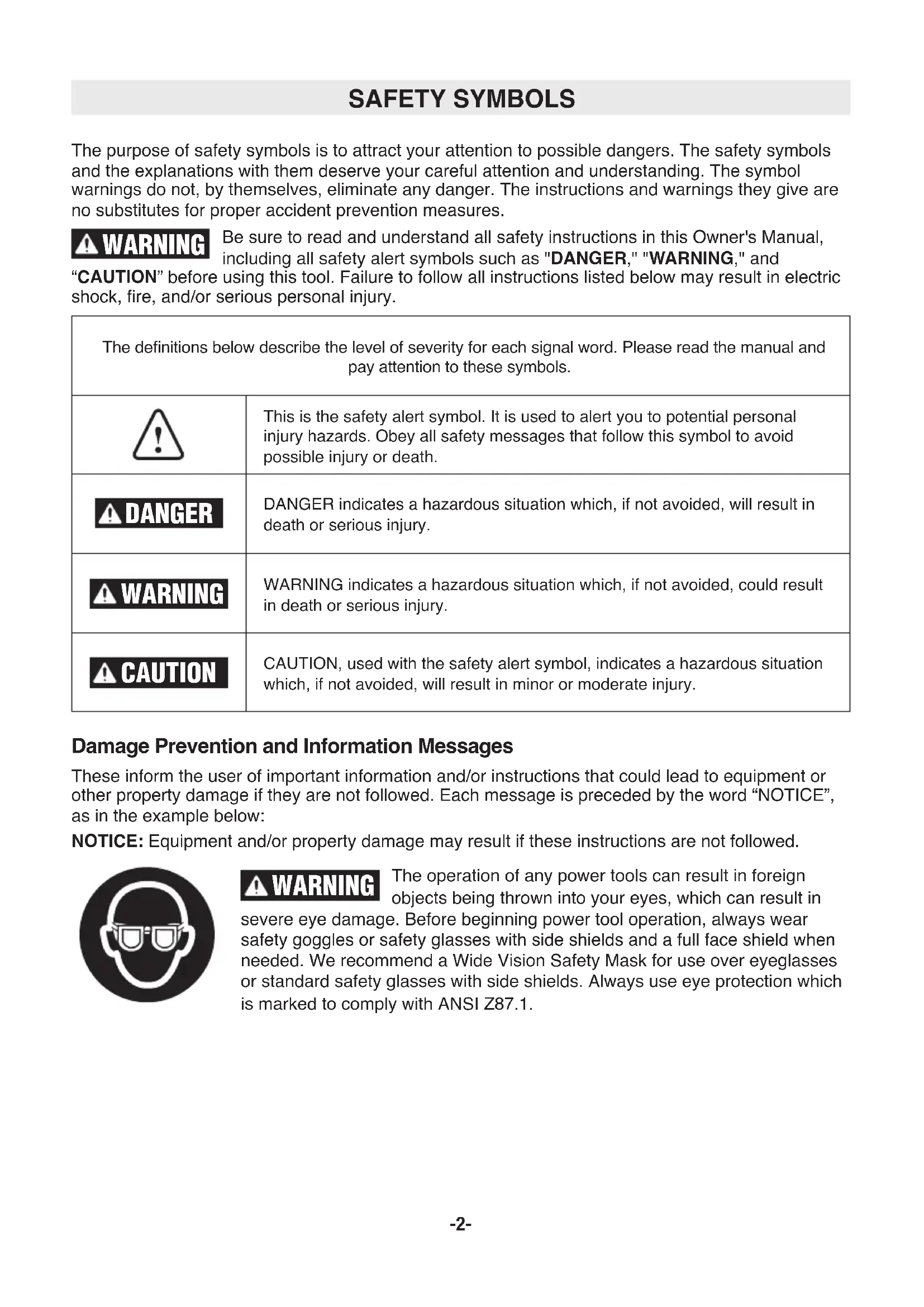
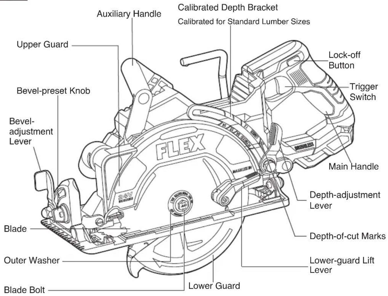
FUNCTIONAL DESCRIPTIONS& SPECIFICATIONS
Brushless Circular Saw
Fig. 1
| Model No. FX 2141R | |
| Rated Voltage 24 V d.c. | |
| No-load Speed 6200/min (RPM) | |
| Bevel Capacity 0 – 56° | |
| Blade Diameter 7-1/4” (184 mm) | |
| Blade Arbor Hole 5/8” (16 mm) | |
| Max. Cutting Depth at 0° Bevel 2-5/8” (66 mm) | |
| Max. Cutting Depth at 45° Bevel 1-7/8” (48 mm) | |
| Max. Cutting Depth at 56° Bevel 1-1/2” (38 mm) | |
| Recommended operating temperature -4 – 104°F (-20 – 40°C) | |
| Recommended storage temperature < 122°F (< 50°C) |

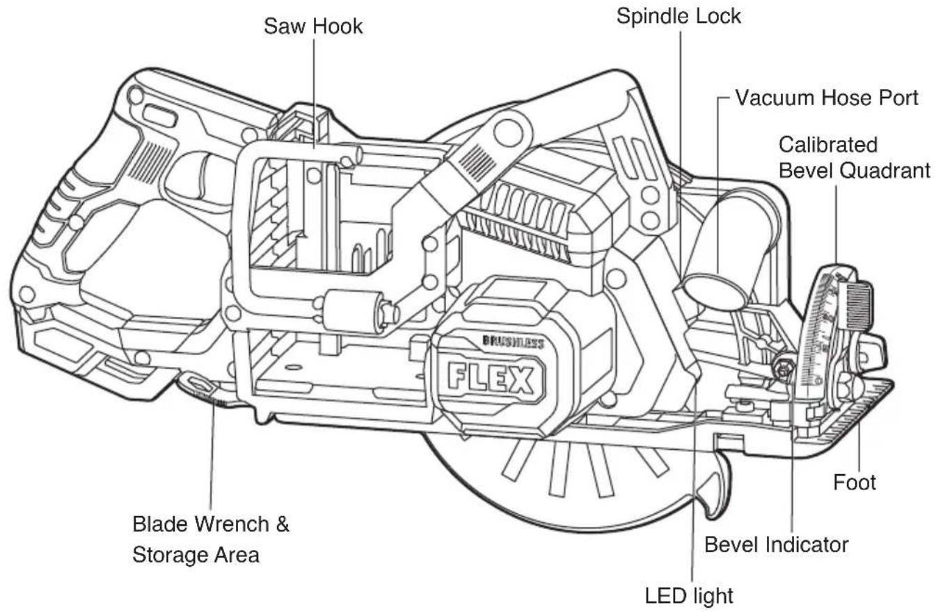
Detach the battery pack from the tool before
making any assembly, adjustments or changing accessories. Such preventive safetymeasures reduce the risk of starting the tool accidentally.
TO ATTACH/DETACH BATTERY PACK (FIG. 2)
To attach the battery pack:
Align the raised rib on the battery pack with the grooves in the tool, and then slide the battery pack onto the tool.
NOTICE: Make sure that the latch on the battery pack snaps into place and that the battery pack is secured to the tool before beginning operation.
NOTICE: When placing the battery pack onto the tool, be sure that the raised rib on the battery pack aligns with the groove inside the tool and that the latches snap into place properly. Improper attachment of the battery pack can cause damage to internal components.
To detach the battery pack:
Depress the battery-release button located on the front of the battery pack, to release the battery pack. Pull the battery pack out and remove it from the tool.

Battery tool is always in operating condition.
Therefore, remove the battery when the tool is not in use or when carrying it at your side.
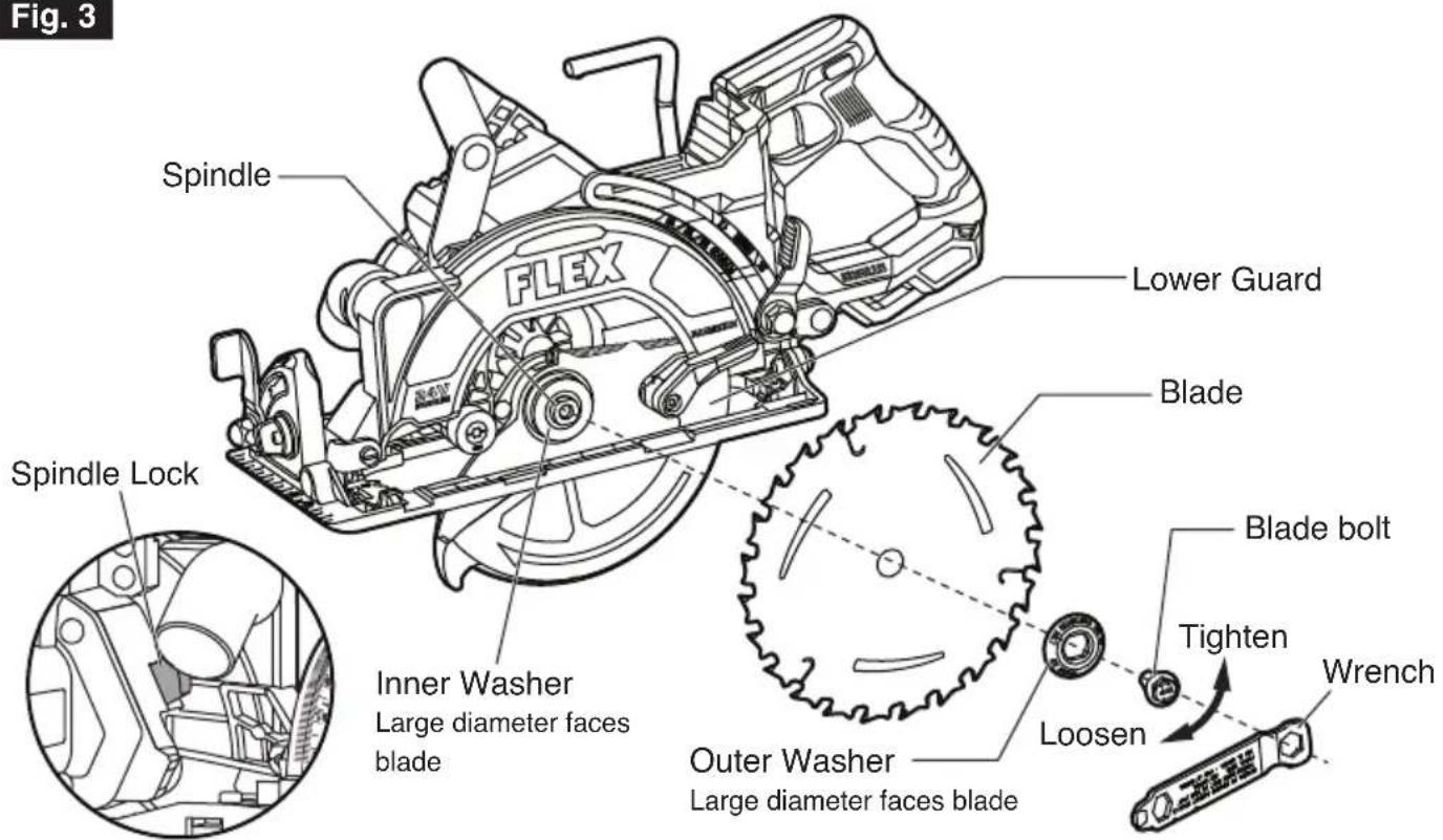
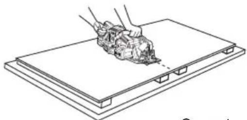
ATTACHING THE BLADE (FIG. 3)

This tool is for cutting wood only. Use only the correct saw blades for wood-cutting operations. Do not use any abrasive wheels.

Use only 7-1/4" saw blades rated 6200/min (RPM) or greater. NEVER use a blade that is so thick that it prevents the outer blade washer from engaging with the flat side of the spindle.
Using a blade not designed for the saw may result in serious personal injury and property damage.

Be sure to wear protective work gloves while
handling a saw blade. The blade can injure unprotected hands.
a. Detach the battery pack.
b. Press the spindle lock and turn the blade bolt with included blade wrench until the lock engages. The spindle is now locked. Continue to depress the spindle lock, turn the blade wrench clockwise, and remove the blade bolt and the outer washer. Always clean the spindle, washers, upper guard, and lower guard to remove any dirt and sawdust.

Depress the spindle lock only when the tool is at a
standstill.
c. Make sure that the saw teeth and the arrow on the blade point in the same direction as the arrow on the lower guard.
d. Retract the lower guard all the way up into the upper guard. While retracting the lower guard, check the operation and condition of the lower guard system.
e. Slide the blade through the slot in the foot and mount it against the inner washer on the shaft. Be sure that the clamping surfaces of the inner and outer washers lay flush against the blade.

Make sure that the clamping surfaces of the inner and outer washers are perfectly clean and face the blade.
f. Reinstall the outer washer. First finger-tighten the blade bolt, then tighten the blade bolt 1/8 turn (45°) with the blade wrench (this ensures slippage of the saw blade when it encounters excessive resistance, thus reducing motor overload and saw kickback).
NOTICE: Do not use a blade wrench with a longer handle, since it may lead to over tightening of the blade bolt.
Fig. 3
ADJUSTMENTS

Detach the battery pack from the tool before
performing any assembly, adjustments, or changing accessories. Such preventive safety measures reduce the risk of starting the tool accidentally.
DEPTH-OF-CUT ADJUSTMENT (FIG. 4a & 4b)
Your tool is equipped with a depth-of-cut adjustment lever, located beside the upper guard.
To set the depth of cut:
a. Remove the battery pack from the circular saw.
b. Loosen the depth-adjustment lever by pushing it up (Fig. 4a).
c. Hold the foot of the saw flat against the edge of the workpiece and use the main handle to raise or lower the saw. Align the bottom contour of the depth-adjustment lever with the desired depth-of-cut mark on the calibrated depth bracket and tighten the lever (Fig. 4a).
NOTICE: Check the desired depth. Not more than one tooth length of the blade should extend below the material to be cut to minimize splintering (Fig. 4b).
The four most common cutting depths are marked on the calibrated depth bracket. These settings help the operator to quickly set the saw to cut through the material with thickness of 1/4", 1/2", 3/4" plywood, 1x, 2x, and 3x lumber respectively, while allowing one tooth length of the blade to extend below the material.
Fig. 4a
Depth-of-cut Mark
natural_image
Technical line drawing of a mechanical assembly with no visible text or symbolsBottom Contour of Depth-adjustment Lever
Fig. 4b
Depth-adjustment Lever
One tooth length should penetrate wood for minimum splintering
90° CUTTING ANGLE CHECK (FIG. 5)
a. Remove the battery pack from the circular saw. Set the foot to the maximum depth of cut setting.
b. Loosen the bevel-adjustment lever and set the bevel indicator to 0^ on quadrant. Retighten the lever, and check for 90^ angle between the blade and bottom plane of foot with a square.
c. Use a 3/32" allen wrench (not included) to make adjustments, if necessary, by turning the small alignment screw from the bottom side of the foot.
Fig.5
BEVEL ADJUSTMENT (FIG. 6)
a. Remove the battery pack from the circular saw.
b. Loosen the bevel-adjustment lever at the front of the saw. Tilt the saw foot and align the bevel indicator to the desired angle on the calibrated quadrant, and then tighten the bevel-adjustment lever.
Bevel-preset Knob
The bevel-preset knob allows the operator to quickly set bevel at 22.5^, 45^ and 56^ .
The bevel-preset knob of your saw was set to 56° at the factory.
a. Push the bevel-preset knob and turn it to one of the desired setting (22.5°/ 45°/ 56°).
b. Release the bevel-preset knob and it will serve as a travel stop when adjusting the bevel angle.
WARNING
Because of the increased amount of blade
engagement in the work and decreased stability of the foot, blade binding may occur. Keep the saw steady and the foot firmly on the workpiece.
Fig. 6
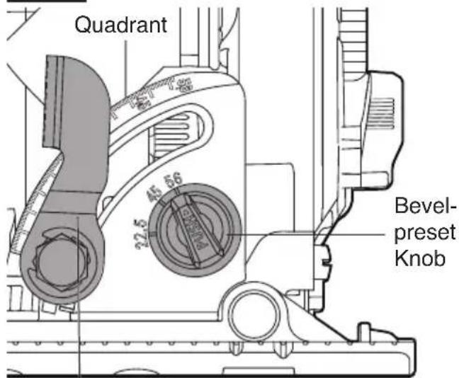
Bevel-adjustment Lever
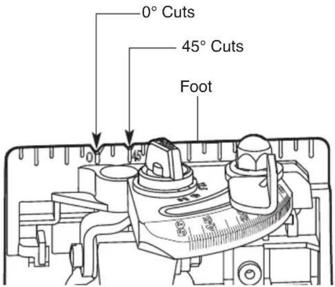
LINE GUIDE (FIG. 7)
For a 0^ cut, use the large notch in the foot for guidance. For 45^ bevel cuts, use the small notch. The cutting guide notch will indicate an approximate line of cut. Make sample cuts in scrap lumber to verify the actual line of cut. This will be helpful because of the number of different blade types and thicknesses available. To ensure minimum splintering on the good side of the material to be cut, face the good side down.
Fig. 7
WRENCH USAGE
The wrench provided has several functions (Fig. 8a):
- 1/2" wrench is used to loosen/tighten the blade bolt.
- 9/16" wrench is used to loosen/tighten the bevel/depth levers when levers are over-tightened or additional tightening is needed.
- Blade diamond arbor knock out (wedge feature).
Storage is provided on the tool (Fig. 1). The wrench is fully seated when the second lock detent is engaged.
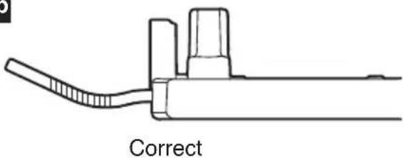
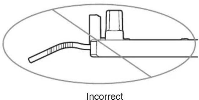
NOTICE: The wrench needs to be inserted with the correct orientation (Fig. 8b). Damage to the work piece could occur if inserted incorrectly.
Fig. 8a
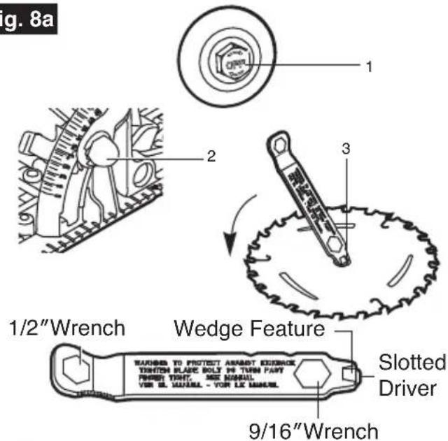
Fig. 8b
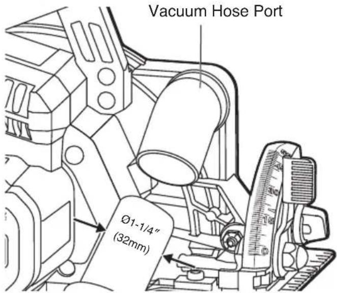
VACUUM HOSE PORT (FIG. 9)
Your tool is equipped with a vacuum hose port for connection to vacuum / dust extractor hoses with ∅1-1/4" (32mm).
Use a suitable vacuum extractor hose or use an adapter, if necessary.

Never allow a vacuum / dust extractor hose to
interfere with the lower guard or cutting operation.
Fig. 9
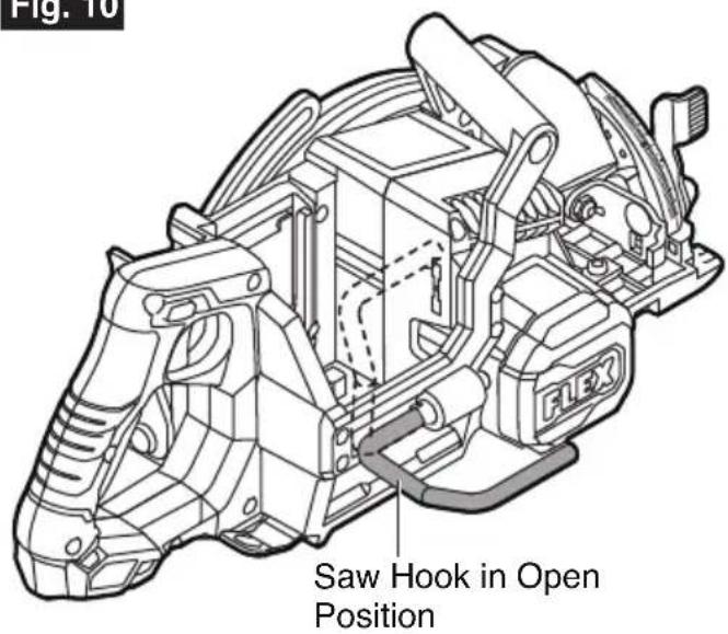
SAW HOOK (FIG. 10)
Your tool is equipped with a hook. Use the hook to hang the saw from a rafter or beam, or other similar secure structure for temporary storage during work breaks. Recommended lumber size to support the saw with the hook: 2x4.
To use, pivot the hook to the right side until it snaps into the open position.
When not in use, always pivot the hook back until it snaps into the closed position.

When the saw is hung by the hook, do not shake the
saw or the object that it is hanging from. Do not hang the saw from any electrical wires. Make sure that the structure used to hang the saw is secure. Personal injury or property damage may occur.
Only use the hook for hanging the saw.
Using the hook to hang anything else could lead to serious injury.
Do not use the hook to reach another object or use the hook to support your weight in any situation.
Fig. 10
OPERATING INSTRUCTIONS

To reduce the risk of fire, personal injury, and
product damage due to a short circuit, never immerse your tool, battery pack or charger in fluid or allow a fluid to flow inside them.
Corrosive or conductive fluids, such as seawater, certain industrial chemicals, and bleach or bleach-containing products, etc. can cause a short circuit.

If any parts are damaged or missing, do not operate
this product until the parts are replaced. Use of this product with damaged or missing parts could result in serious personal injury.

Do not attempt to modify this tool or create
accessories not recommended for use with this tool. Any such alteration or modification is misuse and could result in a hazardous condition leading to possible serious injury.

To prevent accidental starting that could cause
serious personal injury, always remove the battery pack from the tool when assembling parts, making adjustments, or cleaning the tool.
This circular saw must be used only with the battery packs and chargers listed below:
| Battery Pack Charger | |||||||
| 2.5Ah 3.5Ah | 5Ah 6Ah 8 | Ah 10Ah 12Ah | FLEXFX0411FX0421FX0431FX0451 | ||||
| FLEXFX0111 | FLEXFX0321 | FLEXFX0121 | FLEXFX0331 | FLEXFX0221 | FLEXFX0341 | FLEXFX0231 | |
NOTE: For best performance, we recommend using FLEX battery pack that is 10Ah (FX0341) and higher with this tool.
NOTICE: Please refer to the battery pack and charger manuals for detailed operating information.
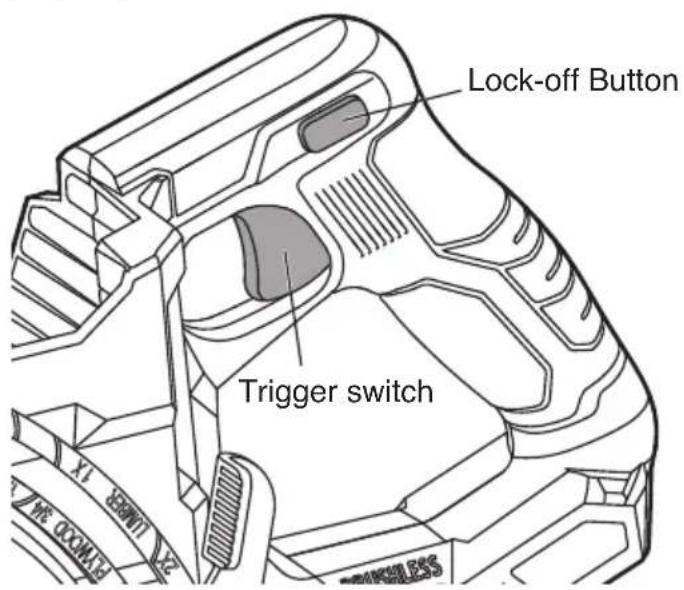
TRIGGER SWITCH AND LOCK-OFF BUTTON (FIG. 11)
To turn the tool "ON", press and hold the lock-off button with your thumb, then squeeze the trigger switch with your finger. Release the lock-off button and continue to squeeze the trigger for continued operation.
To turn the tool "OFF", release the trigger switch, which is spring loaded and will return to the off position automatically.
Your saw should be running at full speed BEFORE starting the cut, and turned off only AFTER completing the cut. To increase switch life, do not turn switch on and off while cutting.
Fig. 11
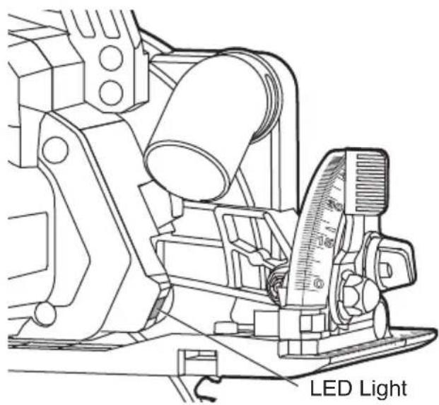
LED LIGHT (FIG. 12)
Your tool is equipped with a LED light, located behind the upper guard. This provides additional light on the saw blade and the surface of the workpiece for operation in lower light areas. The LED light will automatically turn on with a slight squeeze on the trigger switch before the tool starts running. It will turn off approximately 10 seconds after the trigger switch is released.
NOTE: When the tool and/or battery pack become overloaded or too hot, the internal sensors will turn the tool off and the LED light will rapidly flash. Rest the tool for a while or place the tool and battery pack separately under air flow for cooling.
The LED light will flash more slowly to indicate that the battery pack is at low-battery capacity. Recharge the battery pack.
Fig. 12
INTENDED USE
This tool is designed to perform all wood-cutting applications: general cuts, cross cuts, rip cuts, and plunge cuts. Only use with wood materials.
NOTICE: The tool is not designed for metal
or masonry cutting. Dust and chips from those materials will impact lower guard function.

WARNING
Do not use abrasive wheels with circular saws.
Abrasive dust may cause lower guard to not operate properly.
GENERAL CUTS

Always be sure that neither hand interferes
with the free movement of the lower guard.

After completing a cut and releasing the trigger, be
aware of the necessary time it takes for the blade to come to a complete stop during coast down. Do not allow the saw to brush against your leg or side; since the lower guard is retractable, it could catch on your clothing and expose the blade. Be aware of the necessary blade exposures that exist in both the upper and lower guard areas.
Always hold the saw by the main handle with one hand and the auxiliary handle with the other. Maintain a firm grip with both hands on the saw and position your arms to resist kickback forces. Position your body to either side of the blade, but not in line with the blade. To resume cutting after cutting is interrupted, press the lock-off button, squeeze the trigger, and allow the blade to reach full speed, then re-enter the cut slowly, and resume cutting. When cutting across the grain, the fibers of the wood have a tendency to tear and lift. You can minimize this effect by advancing the saw slowly. For a finished cut, a cross cut blade or miter blade is recommended.
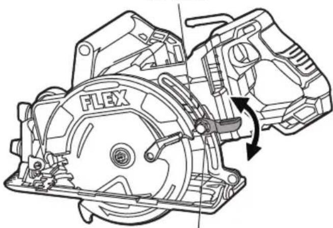
PLUNGE CUTS (FIG. 13)
a. Remove the battery pack from the circular saw.
b. Set the depth adjustment according to the thickness of the material to be cut.
c. Attach the battery pack.
d. Hold the main handle of the saw with one hand, tilt the saw forward, and rest the front of the foot plate on the material to be cut. Align the cutting-guide notch with the line you've drawn. Use the lower-guard lift lever to raise the lower guard until you are able to grasp and hold the auxiliary handle with the other hand.
e. Position the saw so that the blade is just clearing the material to be cut. Start the saw and, once it is fully up to speed, use the front edge of the foot as a hinge point to gradually lower the back end of the saw.
f. Once the foot plate rests flat on the surface being cut, release the lower-guard lift lever. Proceed cutting in the forward direction to the end of cut.
WARNING
Allow the blade to come to a complete stop before
lifting the saw from the cut. Also, never pull the saw backward, since the blade will climb out of the material and KICKBACK will occur.
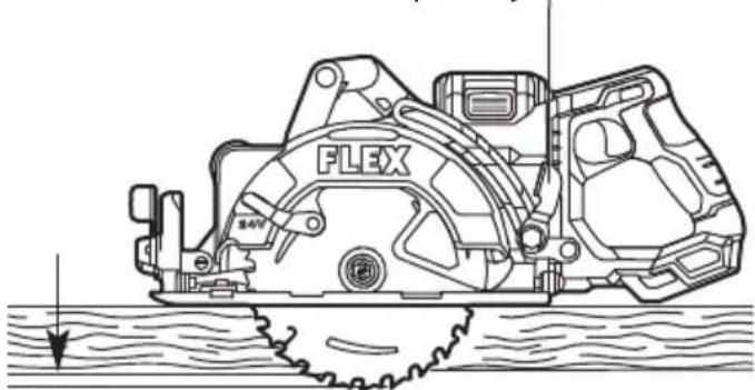
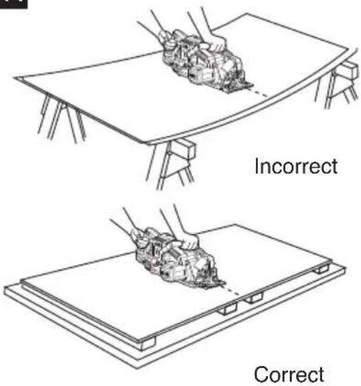
CUTTING LARGE SHEETS (FIG. 14)
Large sheets and long boards can sag or bend, depending on support. If you attempt to cut without leveling and properly supporting the piece, the blade will tend to bind, causing KICKBACK and extra load on the motor.
Support the panel or board close to the cut. Be sure to set the depth of the cut so that you cut through the sheet or board only and not the table or work bench that is supporting it. The two-by-fours used to raise and support the work should be positioned so that the wide sides support the work and rest on the table or bench. Do not support the work with the narrow sides, as this is an unsteady arrangement. If the sheet or board to be cut is too large for a table or work bench, use the supporting two-by-fours on the floor and secured in place.

g. Turn the saw around and finish the cut in the normal manner, sawing forward. If corners of your plunge cut are not completely cut through, use a jigsaw or hand saw to finish the corners.
Fig. 14
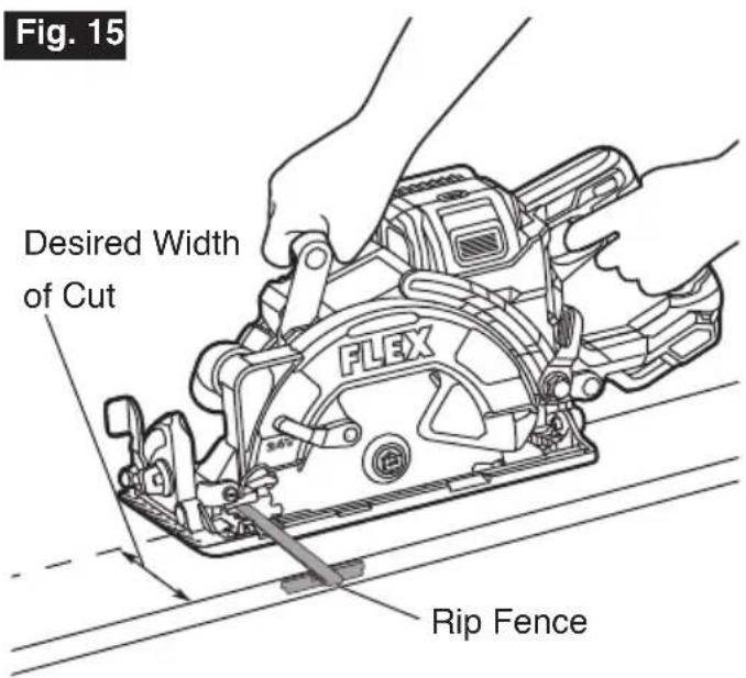
RIP CUTS (FIG. 15)
The combination blade provided with your saw is for both cross cuts and rip cuts. Ripping is cutting lengthwise with the grain of the wood. Rip cuts are easy to do with a rip fence. Rip fence FLEX FT211 is available as an accessory (not included). To attach a fence, insert the fence through the slots in the foot to the desired width as shown, and secure it with the thumb screw (included in the rip fence kit).
WARNING
Ensure that the rip fence does not interfere with the
free movement of the lower guard and saw blade. A rip fence contacting the lower guard or saw blade can cause property damage and serious personal injury.
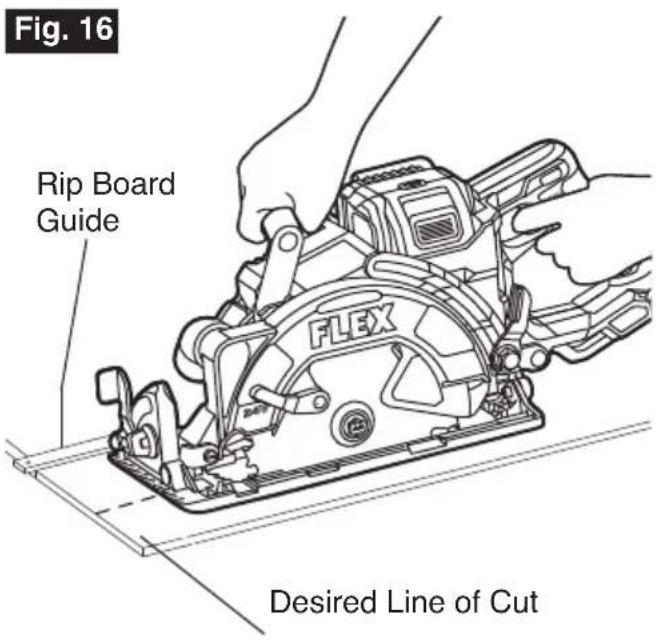
RIP BOARD GUIDE (FIG. 16)
When rip cutting large sheets, the rip fence may not allow the desired width of cut. Clamp or nail a straight piece of 1" (25 mm) lumber to the sheet as a guide. Use the right side of the foot against the board guide.
WARNING
Ensure that the clamps do not interfere with the free
movement of the saw.
MAINTENANCE

To avoid serious personal injury, always remove the battery pack from the tool when cleaning or performing any maintenance.
SERVICE

Preventive maintenance performed by
unauthorized personnel may result in misplacing of internal wires and components which could cause a serious hazard. We recommend that all tool service be performed by a FLEX Factory Service Center or Authorized FLEX Service Station.
GENERAL MAINTENANCE

When servicing, use only identical replacement parts. Use of any other parts could create a hazard or cause product damage. Periodically inspect the entire product for damaged, missing, or loose parts such as screws, nuts, bolts, caps, etc. Tighten securely all fasteners and caps and do not operate this product until all missing or damaged parts are replaced. Please contact customer service or an authorized service center for assistance.
CLEANING

The tool may be cleaned most effectively with
compressed dry air. Always wear safety goggles when cleaning tools with compressed air. Ventilation openings and switch levers must be kept clean and free of foreign matter. Do not attempt to clean by inserting pointed objects through openings.

Certain cleaning agents and solvents damage
plastic parts. Some of these are: gasoline, carbon tetrachloride, chlorinated cleaning solvents, ammonia and household detergents that contain ammonia.
Storage
Store the tool indoors in a place that is inaccessible to children. Keep away from corrosive agents.
Care of Blades
Blades become dull even from cutting regular lumber. If you find yourself forcing the saw forward to cut instead of just guiding it through the cut, chances are the blade is dull or coated with wood pitch.
When cleaning gum and wood pitch from blade, detach the battery pack and remove the blade. Remember, blades are designed to cut, so handle them carefully. Wear gloves and wipe the blade with kerosene or similar solvent to remove the gum and pitch.
Unless you are experienced in sharpening blades, we recommend you do not try.
ACCESSORIES

The use of any other accessories not specified in this manual may create a hazard.
Blade wrench Blade
FLEX 5 YEAR LIMITED WARRANTY
Chervon North America, Inc. ("Seller") warrants to the original purchaser only, that all FLEX 24V products will be free from defects in material or workmanship for a period of five years from date of purchase when the original purchaser registers the product within 30 days from the date of original retail purchase and retains their receipt as proof of purchase. THE 5-YEAR LIMITED WARRANTY PERIOD IS CONDITIONED ON REGISTRATION OF THE PRODUCT WITHIN 30 DAYS OF PURCHASE AND ONLY APPLICABLE TO FLEX 24V TOOLS, BATTERIES AND CHARGERS. If the original purchaser does not register their product within 30 days, the foregoing limited warranty will apply for a duration of three years. Product registration can be completed online at www.registermyflex.com.
24V Tools: 5-Year Limited Warranty with Registration
24V Batteries and Chargers: 5-Year Limited Warranty with Registration
Corded, 12V and 20V FLEX Legacy Products: 1-Year Limited Warranty, No Registration Benefit
Accessories and Attachments: No Warranty
SELLER'S SOLE OBLIGATION AND YOUR EXCLUSIVE REMEDY under this 5-Year Limited Warranty and, to the extent permitted by law, any warranty or condition implied by law, shall be the repair or replacement of parts, without charge, which are defective in material or workmanship and which have not been misused, carelessly handled, or repaired by persons other than a FLEX Authorized Service Dealer. This warranty does not cover part failure due to normal wear and tear. To make a claim under warranty, return the complete product, transportation prepaid, to any FLEX Authorized Service Dealer. For Authorized FLEX Service Dealers, please visit www.registermyflex.com or call 1-833-FLEX-496 (1-833-353-9496).
This 5-Year Limited Warranty does not apply to accessories, attachments or parts.
Any implied warranties applicable to a product shall be limited in duration equal to the duration of the express warranties applicable to such product, as set forth in the first paragraph above. Some states in the U.S. and some Canadian provinces do not allow limitations on how long an implied warranty lasts, so the above limitation may not apply.
FLEX is not responsible for direct, indirect, incidental or consequential damages. Some U.S. states and Canadian provinces do not allow limitations on how long an implied warranty lasts and/or do not allow the exclusion or limitation of incidental or consequential damages, so the above limitations or exclusions may not apply. This limited warranty gives you specific legal rights, and you may also have other rights which vary by state in the U.S. and by province in Canada.
This limited warranty applies only to products sold within the United States of America, Canada and the commonwealth of Puerto Rico. For warranty coverage within other countries, contact your local FLEX dealer.
© Chervon North America, 1203 E. Warrenville Rd., Naperville, IL 60563
www.flexpowertools.com
www.registermyflex.com
1-833-FLEX-496 (1-833-353-9496)
SYMBOLES RELATIFS À LA SÉCURITÉ
natural_image
Icon of a person wearing glasses inside a circle (no text or symbols)AVERTISSEMENT
POUR ATTACHER LA LAME (FIG. 3)
AVERTISSEMENT
natural_image
Technical line drawing of a mechanical assembly with no visible text or symbolsORIFICE DU TUYAU D'ASPIRATION (FIG. 9)
natural_image
Line drawing of a mechanical assembly with hands operating a component on a flat base (no text or symbols)Correct
COUPES EN LONG (FIG. 15)
© Chervon North America, 1203 E. Warrenville Rd., Naperville, IL 60563
www.flexpowertools.com
www.registermyflex.com
1-833-FLEX-496 (1-833-353-9496)
natural_image
Icon of a person wearing glasses inside a circle (no text or symbols)ADVERTENCIA
natural_image
Technical line drawing of a mechanical assembly with no visible text or symbolsCORTES AL HILO (FIG. 15)
Llave hexagonal Hoja
GARANTÍA LIMITADA DE 5 AÑOS FLEX
© Chervon North America, 1203 E. Warrenville Rd., Naperville, IL 60563
www.flexpowertools.com
www.registermyflex.com
1-833-FLEX-496 (1-833-353-9496)
Revisado 10/2021


- Damage Prevention and Information Messages
- SAVE ALL WARNINGS AND INSTRUCTIONS FOR FUTURE REFERENCE.
- Work area safety
- Electrical safety
- Personal safety
- Power tool use and care
- Battery tool use and care
- Service
- SAFETY INSTRUCTIONS FOR CIRCULAR SAWS
- Cutting procedures
- Kickback causes and related warnings
- Lower guard function
- ADDITIONAL SAFETY WARNINGS
- WARNING
- SYMBOLS
- SYMBOLS (CERTIFICATION INFORMATION)
- FUNCTIONAL DESCRIPTIONS& SPECIFICATIONS
- Brushless Circular Saw
- TO ATTACH/DETACH BATTERY PACK (FIG. 2)
- To attach the battery pack:
- To detach the battery pack:
- ATTACHING THE BLADE (FIG. 3)
- standstill.
- ADJUSTMENTS
- Detach the battery pack from the tool before
- DEPTH-OF-CUT ADJUSTMENT (FIG. 4a & 4b)
- 90° CUTTING ANGLE CHECK (FIG. 5)
- BEVEL ADJUSTMENT (FIG. 6)
- Bevel-preset Knob
- LINE GUIDE (FIG. 7)
- WRENCH USAGE
- VACUUM HOSE PORT (FIG. 9)
- SAW HOOK (FIG. 10)
- OPERATING INSTRUCTIONS
- TRIGGER SWITCH AND LOCK-OFF BUTTON (FIG. 11)
- LED LIGHT (FIG. 12)
- INTENDED USE
- GENERAL CUTS
- PLUNGE CUTS (FIG. 13)
- Allow the blade to come to a complete stop before
- CUTTING LARGE SHEETS (FIG. 14)
- RIP CUTS (FIG. 15)
- Ensure that the rip fence does not interfere with the
- RIP BOARD GUIDE (FIG. 16)
- Ensure that the clamps do not interfere with the free
- MAINTENANCE
- GENERAL MAINTENANCE
- CLEANING
- Storage
- Care of Blades
- ACCESSORIES
- FLEX 5 YEAR LIMITED WARRANTY
- SYMBOLES RELATIFS À LA SÉCURITÉ
- AVERTISSEMENT
- POUR ATTACHER LA LAME (FIG. 3)
- ORIFICE DU TUYAU D'ASPIRATION (FIG. 9)
- COUPES EN LONG (FIG. 15)
- ADVERTENCIA
- CORTES AL HILO (FIG. 15)
- GARANTÍA LIMITADA DE 5 AÑOS FLEX
Brand : Flex
Model : FX2141R
Category : Saw