
CP 143142 - Fan Orbegozo - Free user manual and instructions
Find the device manual for free CP 143142 Orbegozo in PDF.

| Product type | Ceiling fan |
| Brand | Orbegozo |
| Model | CP 143142 |
| Number of speeds | 6 (1 to 6) |
| Rated power | 35 W |
| Maximum air flow | 341.60 m³/min |
| Sound power level | 48.3 dB(A) |
| Maximum air speed | 4.40 m/s |
| Service value | 9.76 (m³/min)/W |
| Standby consumption | 0.30 W |
| Remote control | Yes (AAA batteries not included) |
| Timer | 1h, 2h, 4h, 8h |
| Breeze mode | Yes |
| Direction switch | Yes (summer/winter) |
| Lighting | Integrated LED with color change |
| Minimum installation height | 2.30 m from floor |
| Support load capacity | 50 kg minimum |
| Warranty | In accordance with current legislation |
Frequently Asked Questions - CP 143142 Orbegozo
User questions about CP 143142 Orbegozo
0 question about this device. Answer the ones you know or ask your own.
Ask a new question about this device
Download the instructions for your Fan in PDF format for free! Find your manual CP 143142 - Orbegozo and take your electronic device back in hand. On this page are published all the documents necessary for the use of your device. CP 143142 by Orbegozo.
USER MANUAL CP 143142 Orbegozo
natural_image
White double-decker airship with five blades, no text or symbols visibleCP 143142
Sonifer, S.A.
Avenida de Santiago, 86 30007, Murcia, España. sonifer@sonifer.es / www.orbegozo.com MADE IN P.R.C.
Read this manual carefully before running this appliance and save it for reference in order to obtain the best results and ensure safe use.
Scan this QR code in order to access to more information about this ceiling fan, including installation details. Or enter www.orbegozo.com and look for the model number in the website.
natural_image
Technical line drawing of a mechanical assembly with mounting brackets and directional arrows (no text or symbols)natural_image
Technical diagram of a mechanical assembly with mounting flanges and vertical supports (no text or symbols)natural_image
Technical diagram of a mechanical device with no visible text or symbols
natural_image
Line drawing of a kitchen utensil with a handle and base, showing directional arrows indicating movement (no text or symbols)
natural_image
Line drawing of a lamp with a hanging handle and base, showing internal wiring (no text or symbols)natural_image
Line drawing of a lamp with base and top components, showing motion arrows (no text or symbols)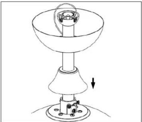
natural_image
Technical line drawing of a mechanical device with a conical base and cylindrical component, showing a downward force arrow (no text or symbols)natural_image
Technical line drawing of a mechanical component with screwdriver and base, no text or symbols presentnatural_image
Technical line drawing of a ceiling fan assembly with circular components and a central hub (no text or symbols)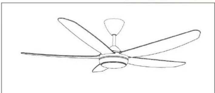
natural_image
Line drawing of a five-blade ceiling fan with a central hub and five blades (no text or symbols)natural_image
Technical line drawing of a mechanical component with an upward arrow indicating motion or force (no text or symbols present)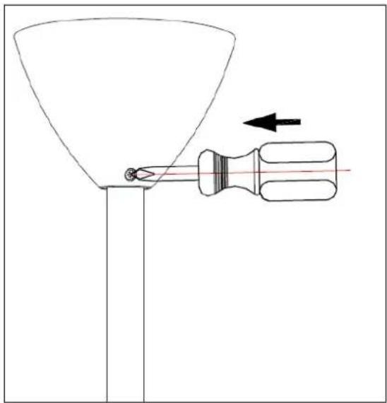
natural_image
Diagram of a funnel being inserted into a screwdriver, with an arrow indicating direction (no text or symbols)Dear Customer, If you follow the recommendations contained in this Instruction Manual, our appliance will give you constant high performance and will remain efficient for many years to come. Read the operating instructions carefully before putting the appliance into operation and keep the instructions including the warranty, the receipt and, if possible, the box with the internal packing. If you give this device to other people, please also pass on the operating instructions.
General Safety Instructions
- This appliance can be used by children aged from 8 years and above and persons with reduced physical, sensory or mental capabilities or lack of experience and knowledge if they have been given supervision or instruction concerning use of the appliance in a safe way and understand the hazards involved. Children must never play with the appliance. Cleaning and user maintenance
must never be carried out by children without supervision.
-
Children should be supervised to ensure that they do not play with the appliance.
-
Keep the appliance and the cable cord out of the reach of children less than 8 years old.
-
WARNING: In order to ensure your children's safety, please keep all packaging (plastic bags, boxes, polystyrene etc.) out of their reach.
-
If the supply cord is damaged it must be repaired by the Authorized Service Agent.
-
Never pull on the cord when unplugging.
-
Do not use the unit with a damaged cord or plug, or if it is not working properly.
-
Do not handle the appliance with wet hands.
-
Never immerse the appliance in water or any other liquid.
-
Make sure the appliance has been unplugged before cleaning.
-
This appliance must be installed following the national regulations for electrical installations.
-
This appliance is for household use only.
-
In case that you need a copy of the instruction manual, you can find it in www.orbegozo.com.
-
WARNING: In case of misuse, there is a risk of possible injury.
Other specific safeguards
-
The method of disconnection from the mains supply must incorporate a switch or isolator with a minimum contact separation of 3 mm.on all poles.
-
Make sure that when the fan is fitted in the chosen position, there is no possibility of the rotating blades coming into contact with any object. Blades should be at least 2.30 m from floor when fan is hung.
-
If you are installing more than one ceiling fan make sure that you do not mix fan blade sets, even though they are from the same ceiling fan model.
-
Before beginning, disconnect power by removing fuse or turning off circuit breaker.
-
Once fan installation is completed make sure that all connections are secure to prevent fan from falling.
-
Fan must be turned off and stopped before reversing fan direction.
-
Check that the means of fitting the fan to the ceiling is capable of supporting the weight of the fan when in operation. (Minimum 50Kg.).
FAN COMPONENTS
 Ceiling support Ceiling support | 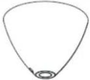 Bowl Bowl | 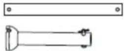 Support bar Support bar |
 Engine Engine | 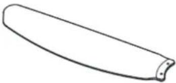 Blades Blades | 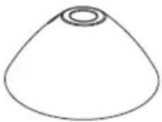 Coupling cover Coupling cover |
 LED lamp LED lamp | 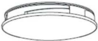 Ceiling Ceiling | 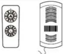 Remote control Remote control |
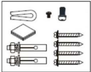 Accessory bagmounting Accessory bagmounting | ||
INSTALLING THE FAN
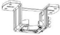
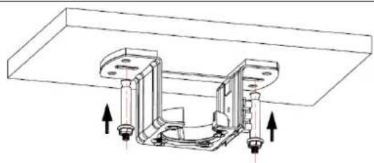
- Attach the ceiling bracket with the two screws and plugs (depending on the type of ceiling)
natural_image
Technical line drawing of a mechanical assembly with mounting brackets and directional arrows indicating movement (no text or symbols)For concrete ceilings, drill two 8mm holes and insert the screw. Align the bracket with the hole and then tighten the nut.
natural_image
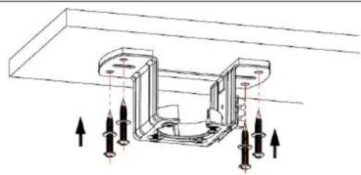
Technical diagram of a mechanical assembly with arrows indicating force or movement (no text or symbols present)On wooden ceilings, secure the bracket using the 4 screws.
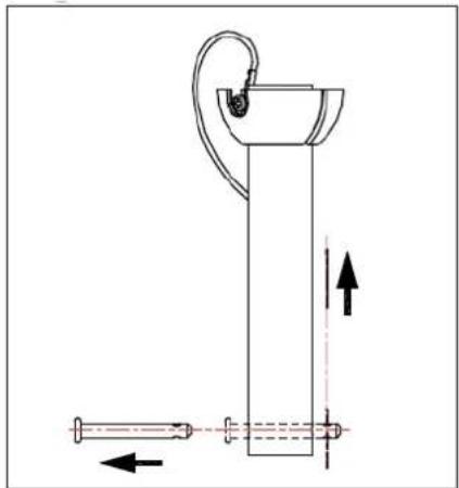
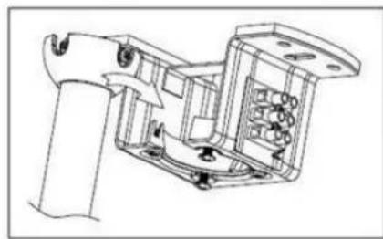
- Pass the support bar through the gap in the coupling cover
natural_image
Technical line drawing of a mechanical device with no visible text or symbols
natural_image
Line drawing of a cleaning or cleaning tool with a funnel and bucket, showing directional arrows (no text or symbols)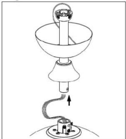
natural_image
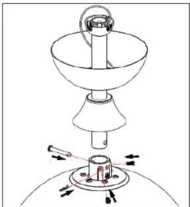
Line drawing of a lamp with a hanging lamp and base, showing internal components and wiring (no text or symbols)- Loosen the motor joint screws and attach the bar with the cover to the motor using the flange pin and screws.
natural_image
Line drawing of a lamp with a base and top components, showing motion arrows (no text or symbols)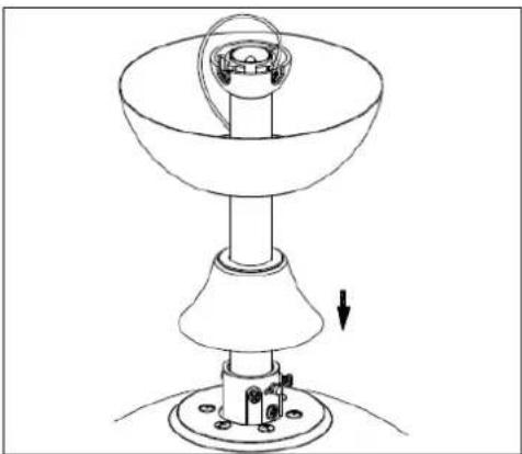
natural_image
Technical line drawing of a mechanical device with a conical base and cylindrical top, showing a rotating component and a downward arrow indicating motion (no text or symbols)CAUTION: It is very important to ensure that the flange pin is correctly installed and secured. Improper pin fastening may result in the fan falling.
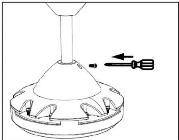
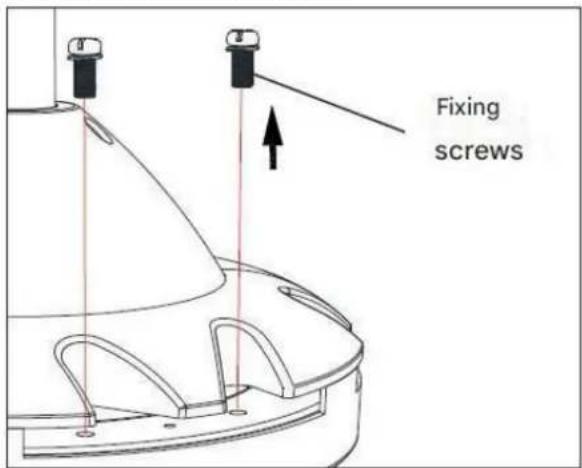
- Remove the screws already pre-installed on the blade holder and screw the blades to the motor head.
natural_image
Technical line drawing of a mechanical component with screwdriver and base, no text or symbols presentScrew the cover on when you put it in position.
INSTALLING THE BLADES
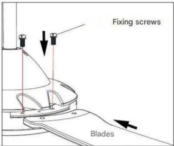
Attach the blades to the motor with the screws.
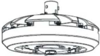
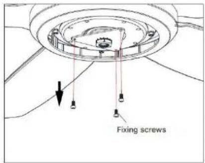
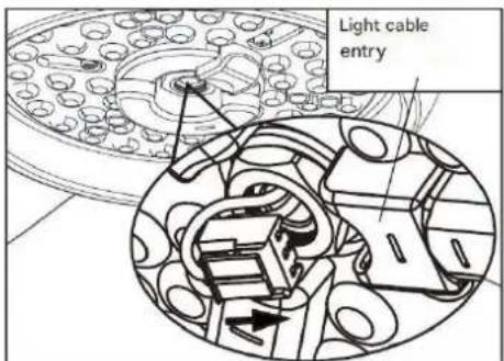
INSTALLING THE LIGHT
natural_image
Technical line drawing of a ceiling fan with a circular vent and rotating base (no text or symbols)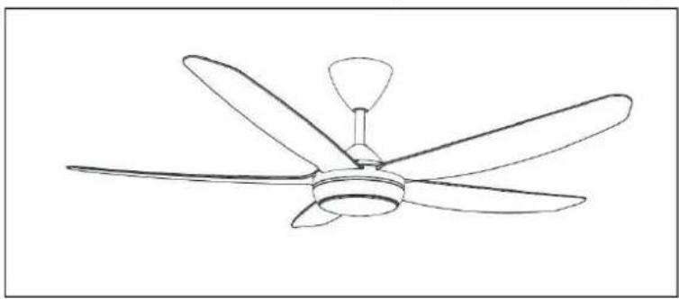
natural_image
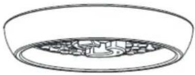
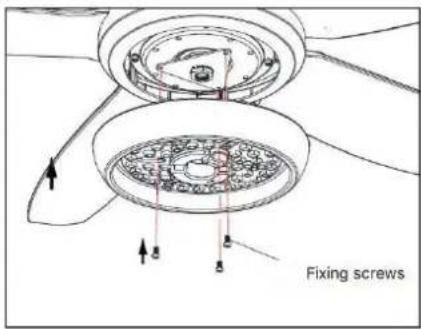
Line drawing of a five-blade ceiling fan with a single propeller (no text or symbols)- Secure the LED board to the fan body with the fixing screws.
Connect the 2 light wires to the LED board correctly and check if they are inserted correctly. Install the diffuser by turning it clockwise.
natural_image
Technical line drawing of a mechanical assembly with no visible text or symbols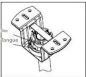
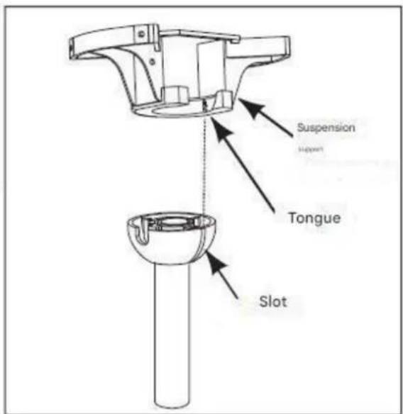
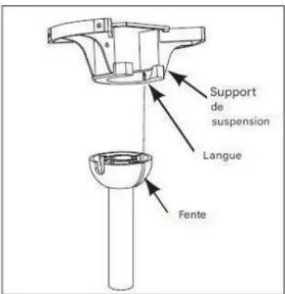
- Carefully lift the fan and place the tilting support bar into the suspension bracket attached to the ceiling. Make sure the ball slot is properly aligned with the tab on the support bar.
WARNING
The fan should be hung with at least 230 cm of clearance from the floor to the blades.
CONNECTING THE REMOTE CONTROL
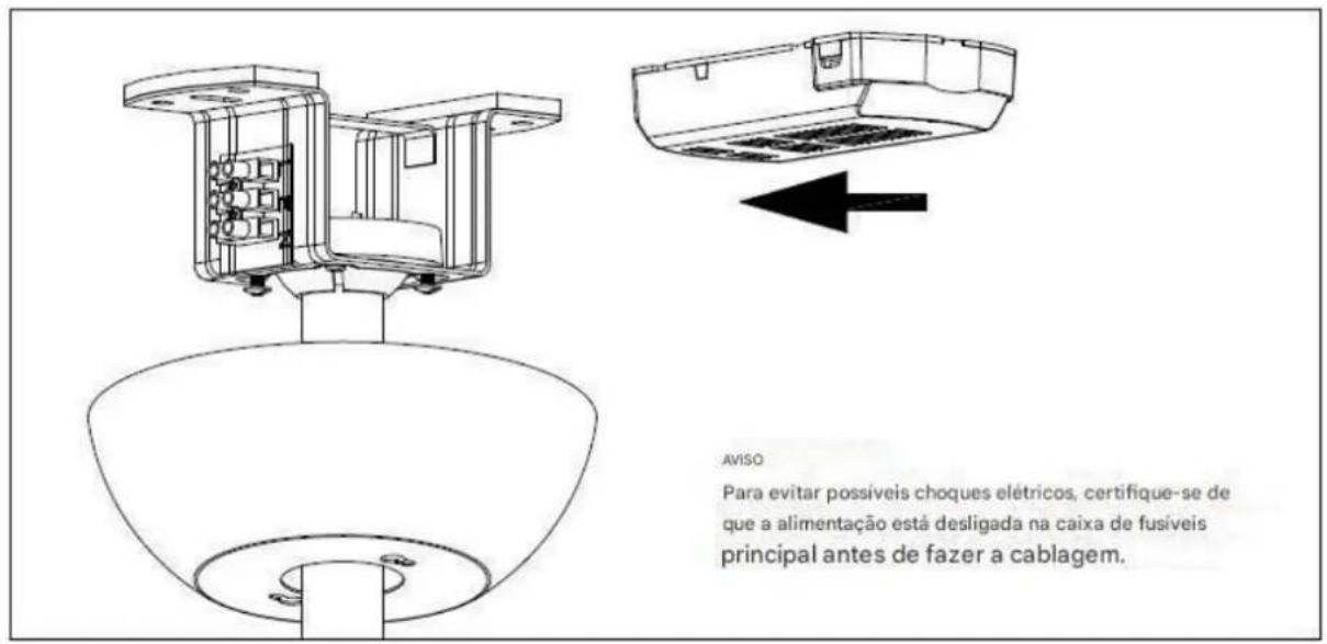
Note: Make sure the power is disconnected from the home's electrical panel before connecting the wiring.
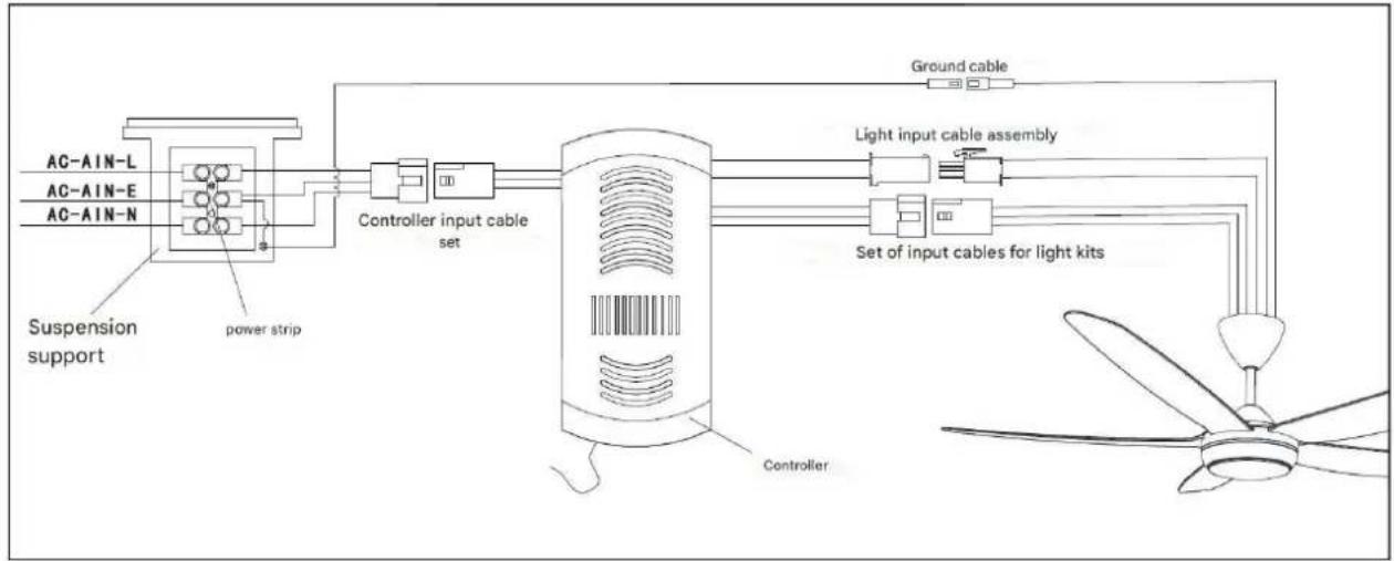
CONTROLLER WIRING DIAGRAM
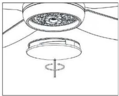
MOUNTING THE BOWL
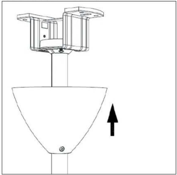
natural_image
Technical line drawing of a mechanical component with an upward arrow indicating motion or force (no text or symbols present)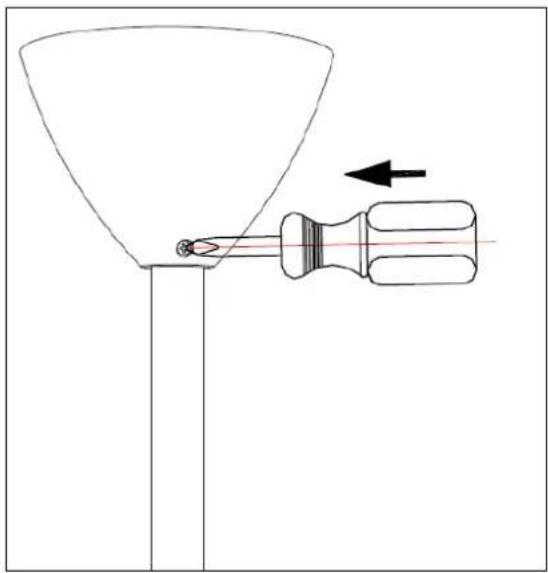
natural_image
Diagram of a funnel being inserted into a screwdriver, with an arrow indicating direction (no text or symbols)Mount the bowl by tightening the two screws
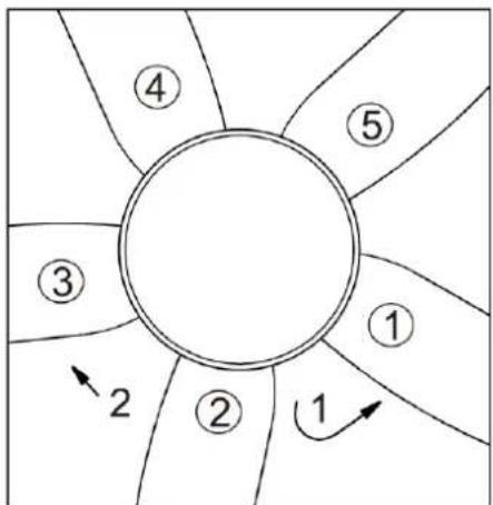
FAN BALANCING
Please note that all ceiling fans are not created equal, even within the same model!
Some may move more or less than others. Movement of a couple of centimeters is quite acceptable and does not result in the fan falling.
Although all blades are weighted and grouped by weight, it is impossible to eliminate wobble completely. This should not be considered a problem. Ceiling fans tend to move during operation because they are generally not rigidly mounted.
BALANCING KIT
If there is any movement after the ceiling fan is installed, confirm whether the screws fixing the suspension ball, ceiling bracket, blade bracket and blade are tight. If one of the above parts is not fastened tightly, re-fix it. If it is properly fixed, proceed as follows.
- Change the position of the fan blades:
If there is no improvement after changing the blade position, remove blades 2 and 3 from the fan and exchange them with each other to observe the effect.
flowchart
graph TD
    A["①"] --> B["②"]
    B --> C["③"]
    C --> D["④"]
    D --> E["⑤"]
    E --> F["⑥"]
    F --> G["⑦"]
    G --> H["⑧"]
    H --> I["⑨"]
    I --> J["⑩"]
    J --> K["⑪"]
    K --> L["⑫"]
    L --> M["⑬"]
    M --> N["⑭"]
    N --> O["⑮"]
    O --> P["⑯"]
    P --> Q["⑰"]
    Q --> R["⑱"]
    R --> S["⑲"]
    S --> T["⑳"]
    T --> U["㉑"]
    U --> V["㉒"]
    V --> W["㉓"]
    W --> X["㉔"]
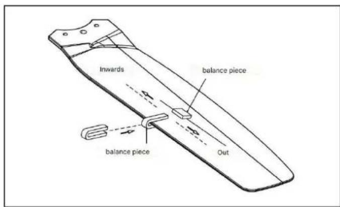
- Adjustment with the balance kit.
A. Take out the balance bag from the package box, use a balance clamp to select one of the fan blades, and clamp the balance clamp on the edge of the rear end of the fan blade.
B. Turn on the fan switch to see if the ceiling fan's movement has been reduced. If it doesn't improve, try a different fan blade. Experiment with all the fan blades in turn to find the blade with the weakest holding balance.
C. Place the balance clamp on the fan blade with the weakest oscillation, move it inward or outward on the edge of the fan blade, turn on the ceiling fan to find the best position of the balance clamp to control the oscillation balance.
D. Take the balance weight, peel off the double-sided tape on the weight, and stick it in the center of the paddle at the position of the balance clip.
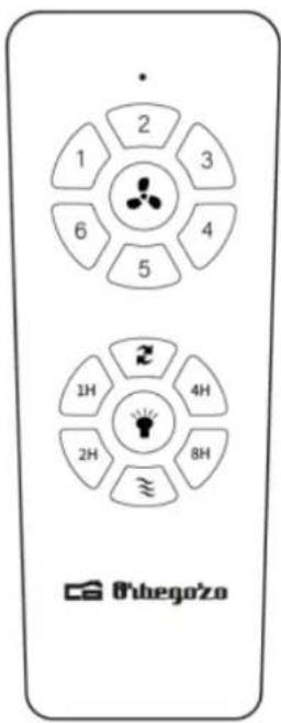
FAN OPERATION
To turn on the fan, press one of the speeds, 1/2/3/4/5/6, with 1 being the lowest and 6 being the highest. You can change the speed at any time by pressing the desired level.

Turn off the ceiling fan

Turn on/off the light (in case your fan has a built-in light)

Breeze mode
This button changes the direction of rotation of the blades. In winter, select the upward rotation, since they will direct he air warm trapped near of the fan toward down throughout the room. When it is hot, select the down spin and the blades will create a breeze that will distribute by the room.
Press 1H: the fan and light will turn off in 1 hour.
Press 2H: the fan and light will turn off in 2 hours.
Press 4H: the fan and light will turn off in 4 hours.
Press 8H: the fan and light will turn off in 8 hours.
To select a light color follow these steps:
-
Turn on the light with the button on the remote control or with the wall switch.
-
Turn it off and on until it lights up the desired color.
-
Once you have selected the color, you must wait at least 10 seconds to turn the light back on once you turn it off.
NOTE: If you turn the light off and then on again within 10 seconds, the light color will change again.
MAINTENANCE AND CLEANING
- Change the battery by opening the battery compartment cover on the remote control, put 2 AAA batteries and make sure the battery polarity matches he diagram of the compartment (Note: The stack No this included). Replace the compartment cover.
- Make sure always of that he compartment of the stack has been left good closed.
- No expose he command to distance to light direct solar
- No try recharge the batteries sold out. There are batteries specials rechargeable, in whose case this clearly specified.
- No pull the batteries to the fire, exists risk of burst.
- Clean the fan with a soft, dry cloth. Never use scouring pads, abrasives or chemical cleaners. Avoid that condensation between in contact with the electrical components.
DISPOSAL OF OLD ELECTRICAL APPLIANCES
The European directive 2012/19/EU on Waste Electrical and Electronic Equipment (WEEE), requires that old household electrical appliances must not be disposed of in the normal unsorted municipal waste stream. Old appliances must be collected separately in order to optimize the recovery and recycling of the materials they contain, and reduce the impact on human health and the environment. The crossed out "wheeled bin" symbol on the product reminds you of your obligation, that when you dispose of the appliance, it must be separately collected. Consumers should contact their local authority or retailer for information concerning the correct disposal of their old appliance.
DECLARATION OF CONFORMITY:
This device complies with the requirements of the Low Voltage Directive 2014/35/EU and the requirements of the EMC directive 2014/30/EU.
GUARANTEE
This appliance is covered and is entitled to the legal guarantee in accordance with the legislation in force from the date of purchase. Keep the purchase receipt to be able to claim your right to the guarantee. To find the closest service to your location, contact through the following web link:
https://orbegozo.com/asistencia-tecnica/
For any type of query, doubt or incident, you can contact us through our email shown on the main page of this manual or through our technical assistance service at https://orbegozo.com/contacto/
Orbegozo is not responsible for components and accessories that are subject to wear and tear due to use, as well as perishable compounds or those that have deteriorated due to improper use. Nor will it be held responsible if the owner has technically modified the device. (Check the legal conditions on our website).
CONSEILS DE SECURITE
natural_image
Technical line drawing of a mechanical assembly with mounting brackets and directional arrows indicating movement (no text or symbols)natural_image
Technical diagram of a mechanical assembly with mounting holes and directional arrows indicating force or movement (no text or labels)natural_image
Technical line drawing of a mechanical device with no visible text or symbols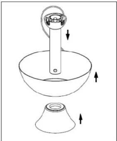
natural_image
Line drawing of a cleaning or cleaning tool with a funnel and bucket, showing directional arrows (no text or symbols)
natural_image
Line drawing of a lamp with a hanging lamp and base, showing internal components and wiring (no text or symbols)natural_image
Line drawing of a lamp with a base and top components, showing motion arrows (no text or symbols)
natural_image
Technical line drawing of a mechanical device with a conical base and cylindrical top, showing a rotating component and a downward arrow indicating motion (no text or symbols)natural_image
Technical line drawing of a mechanical component with screwdriver and base, no text or symbols presentnatural_image
Technical line drawing of a ceiling-mounted device with circular components and a central rotating element (no text or symbols)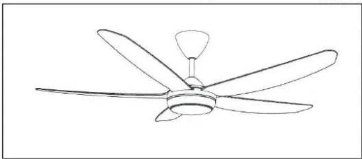
natural_image
Line drawing of a five-blade ceiling fan with a single propeller (no text or symbols)natural_image
Technical line drawing of a mechanical assembly with no visible text or symbols
natural_image
Technical line drawing of a mechanical component with an upward arrow indicator (no text or symbols)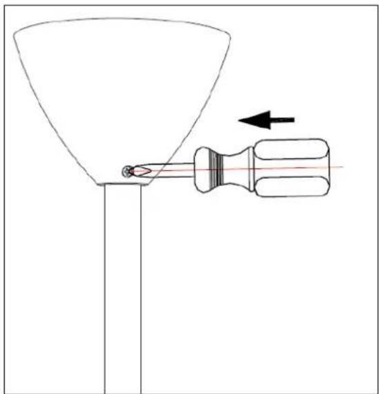
natural_image
Diagram of a funnel being inserted into a screwdriver, with an arrow indicating direction (no text or symbols)Montez le bol en serrant les deux vis
ÉQUILIBRE DU VENTILATEUR
natural_image
Technical line drawing of a mechanical assembly with mounting brackets and directional arrows (no text or symbols)natural_image
Technical diagram of a mechanical assembly with mounting holes and force arrows (no text or labels)natural_image
Technical diagram of a vertical cylindrical device with internal components and directional arrows indicating movement or force (no text or symbols)
natural_image
Line drawing of a kitchen sink and conical bowl with directional arrows indicating motion (no text or symbols)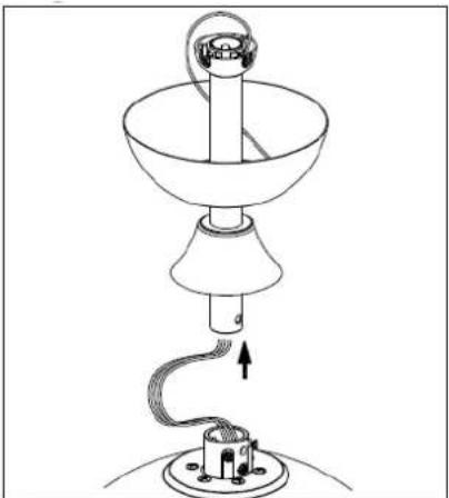
natural_image
Line drawing of a lamp with a hanging lamp and base, showing internal components and wiring (no text or symbols)natural_image
Technical line drawing of a lamp with base and legs, showing internal components and directional arrows (no text or symbols)
natural_image
Technical line drawing of a mechanical device with a conical base and cylindrical top, showing a downward force arrow (no text or symbols)natural_image
Technical line drawing of a mechanical component with screwdriver and base mount (no text or symbols)natural_image
Technical line drawing of a ceiling fan assembly with circular components and a central rotating knob (no text or symbols)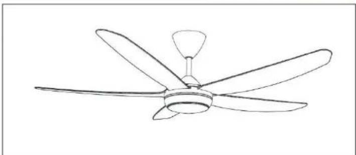
natural_image
Line drawing of a five-bladed air conditioner fan with a central hub (no text or symbols)natural_image
Technical line drawing of a mechanical assembly with no visible text or symbols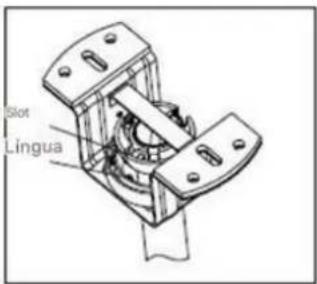
natural_image
Technical line drawing of a mechanical component with an upward arrow indicator (no text or symbols)
natural_image
Diagram of a funnel being inserted into a screwdriver with an arrow indicating direction (no text or symbols)natural_image
Technical line drawing of a mechanical assembly with mounting brackets and directional arrows (no text or symbols)natural_image
Technical diagram of a mechanical assembly with arrows indicating force or movement (no text or symbols present)natural_image
Technical diagram of a mechanical device with no visible text or symbols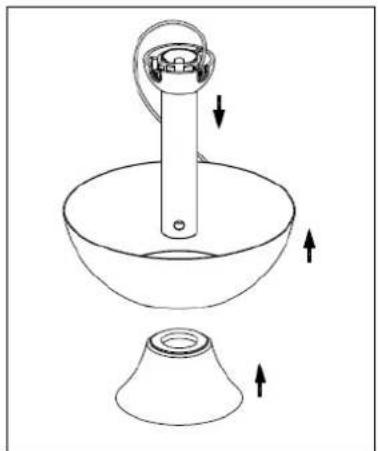
natural_image
Line drawing of a kitchen sink with a funnel and handle, showing directional arrows indicating movement (no text or symbols)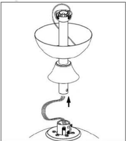
natural_image
Line drawing of a lamp with a hanging handle and base, showing internal wiring (no text or symbols)natural_image
Line drawing of a lamp with base and top components, no text or symbols present
natural_image
Technical line drawing of a mechanical device with a conical base and cylindrical top, showing a downward force arrow (no text or symbols)natural_image
Technical line drawing of a mechanical component with screwdriver and base mount (no text or symbols)natural_image
Technical line drawing of a ceiling fan assembly with central hub and base mount (no text or symbols)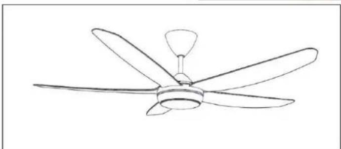
natural_image
Line drawing of a five-blade ceiling fan with a central hub and five blades (no text or symbols)natural_image
Technical line drawing of a mechanical component with an upward arrow indicator (no text or symbols)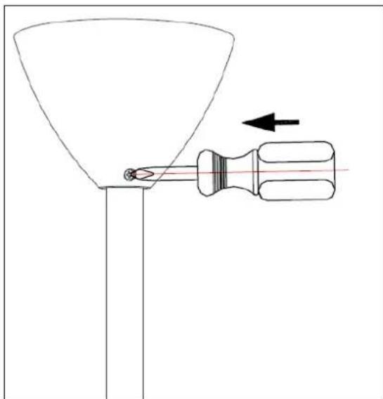
natural_image
Diagram of a funnel being inserted into a screwdriver with an arrow indicating direction (no text or symbols)
- Sonifer, S.A.
- General Safety Instructions
- Other specific safeguards
- INSTALLING THE FAN
- INSTALLING THE LIGHT
- WARNING
- FAN BALANCING
- BALANCING KIT
- FAN OPERATION
- MAINTENANCE AND CLEANING
- DISPOSAL OF OLD ELECTRICAL APPLIANCES
- DECLARATION OF CONFORMITY:
- GUARANTEE
- CONSEILS DE SECURITE
- ÉQUILIBRE DU VENTILATEUR
Brand : Orbegozo
Model : CP 143142
Category : Fan