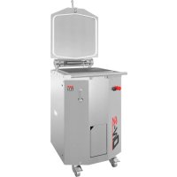
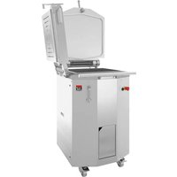
DIVR - Pasta machine JAC - Free user manual and instructions
Find the device manual for free DIVR JAC in PDF.



| Product Type | Professional dough divider |
| Model | DIV-R |
| Brand | JAC |
| Height (lid and frame open) | 1759 mm |
| Width | 600 mm |
| Depth | 772 mm |
| Net weight (round bowl) | 320 kg |
| Net weight (square bowl) | 305 kg |
| Bowl capacity | 19 kg |
| Motor power (50 Hz) | 1.5 kW |
| Motor power (60 Hz) | 1.8 kW |
| Motor type | Three-phase |
| Power supply (220 V) | 50 Hz: 8 A / 60 Hz: 11 A |
| Power supply (380 V) | 50 Hz: 4.5 A / 60 Hz: 6.5 A |
| Rate in division forming | 400 to 3000 pieces/h |
| Rate in bowl division | 900 pieces/h |
| Dough piece weight (division forming) | 19 to 2500 g |
| Dough piece weight (bowl division) | 150 to 950 g (300 to 1900 g with option 10/20) |
| Materials in contact with dough | Square bowl: INOX 304; Round bowl: Cast iron FGL200; Square bowl stamps: GHA-coated aluminum; Round bowl stamps: Teflon-coated cast iron; Knives: INOX 304; Lid: Aluminum AlSi10Mg; Standard grid: INOX 430 Teflon-coated; Profiled grid: INOX 430 Teflon-coated + EN AW-6060 |
| Noise level | < 75 dB(A) (according to EN ISO 3744) |
| Warranty | 5 years (subject to maintenance by approved agent) |
| Daily maintenance | Cleaning of bowl, lid and knives by trained user |
| Weekly maintenance | Interior vacuuming and body washing by trained user |
| Semi-annual maintenance | Oil level inspection by approved agent |
Frequently Asked Questions - DIVR JAC
User questions about DIVR JAC
0 question about this device. Answer the ones you know or ask your own.
Ask a new question about this device
Download the instructions for your Pasta machine in PDF format for free! Find your manual DIVR - JAC and take your electronic device back in hand. On this page are published all the documents necessary for the use of your device. DIVR by JAC.
USER MANUAL DIVR JAC
Traditionally Innovative
PANIFORM
TRADIFORM FullMatic
DIVIFORM+FullMatic
DIVIFORM FullMatic
DIV-R FullMatic
natural_image
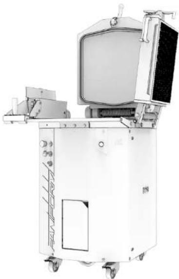
Exterior view of a white industrial machine with control panel and wheels (no visible text or symbols)EN - FR - DE - NL - RU - ES - IT - AR
V02-02-2020

EN- Translation of original user instructions
1 BEFORE COMMISSIONING 6
2 WARRANTY....6
3 WARNINGS....7
4 TECHNICAL SPECIFICATIONS 8
4.1 Technical specifications....8
4.2 Details of materials in direct contact with dough....8
5 INSTALLATION AND COMMISSIONING 9
5.1 Unpacking the machine....9
5.2 Location 9
5.3 Electrical connection 9
5.4 Commercialing 10
5.4 Commissioning 10
5.5 Hazard 10
6 CONTROLS AND SAFETY FEATURES....10
6.1 Controls 10
6.2 Setting area....10
6.3 Work area 10
7 OPERATION....11
8 MAINTENANCE 13
8.1 Daily, by a trained user 13
8.2 Weekly, by a trained user....13
8.3 Six-monthly, by an approved agent....13
9 CONSUMABLES....14
9.1 List of CONSUMABLES 14
10 MALFUNCTIONS....15
11 LIST OF COMPONENTS IN ILLUSTRATIONS....16
1 BEFORE COMMISSIONING
Thank you for choosing a JAC system. It is essential that you read these instructions before installing and commissioning this machine. This will enable you to protect yourself and avoid damaging your machine.
These instructions refer to various illustrations in order to make them easier to understand. These illustrations are at the end of the instructions. Please refer to them whenever you see the following symbols: (fig.x, n°y).
To ensure that your machine gives you full satisfaction over the coming years, we invite you to familiarise yourself with the following advice:
- Enlist the help of your approved agent for installation, commissioning and service support.
- In order to be covered by the 5-year warranty (see terms and conditions set out below), please have your dealer fill in the service booklet when your machine is being installed.
2 WARRANTY

All JAC products are covered by a 5-year warranty.
This warranty is valid for all parts on your machine, including electronic components but excluding consumables. This warranty takes effect on the date the equipment is installed.
Subject to the following restrictive conditions:
- equipment acquired from an approved dealer;
- installation carried out by an approved agent:
- equipment used in accordance with the instructions for use and for the intended purpose for which it was manufactured:
- equipment serviced on a daily basis in compliance with the instructions for use;
- regular servicing by the approved agent in compliance with service specifications, with at least one service a year (servicing chargeable to the user);
- exclusive use of genuine JAC parts.

If there is no record of servicing by an approved agent, warranty cover will be limited to one year.
This warranty does not cover:
- replacement of consumables (§9);
- parts not accepted as defective by our company;
- problems due to improper use of the equipment;
- problems due to installation not carried out by an approved agent;
- parts or problems due to transit damage or improper handling.
The repair and/or replacement of defective parts during the warranty period does not bring about an extension of said warranty.
3 WARNINGS
It is most important that these user instructions be kept with the machine for future reference. Should this machine be sold or transferred to another user, please ensure that the user instructions are handed over so that the new user can be familiarised with its operation and the associated warnings.

These warnings are given for your safety and that of others. We would therefore ask you to read them carefully before installing and using the machine.
This machine has been designed for use by authorised, trained adults. Please therefore ensure that children do not touch it or use it as a toy.
This machine is intended exclusively for professional use.
It is dangerous to modify or attempt to modify the specifications of this machine.
After having installed this machine, please ensure that it is not standing on the power cable.
Follow the instructions given for its use.
This machine must be stored and used in an indoor room, protected from moisture and heat.
This machine must be adequately illuminated to operate it.
The noise level of this machine does not exceed 75 dB(A) in accordance with standard EN ISO 3744.
This machine must be used by one person at a time.
Never use more than one tamping plate at a time. Do not stack multiple tamping plates in the tank.

Never leave dough in the tank for longer than is necessary for the procedures. Always open the lid immediately after the previous step of the operating procedure.
Dough is a living natural product that rises during fermentation. As a result, fermented dough left in the tank for more than a few minutes can exert significant pressure on the lid. This pressure could cause violent movement of the lid when it is opened.
Never use a tool to force the lid open.

Always disconnect the mains socket before cleaning the machine inside/outside and when carrying out maintenance (cf. chapter 8).
This machine is heavy. Take all necessary safety precautions when handling it.
4 TECHNICAL SPECIFICATIONS
4.1 Technical specifications
| DIV-R | DIVIFORM | DIVIFORM+ | TRADIFORM | PANIFORM | |
| Height, lid and frame open (mm) | 1759 | 1604 | 1759 | 1759 | 1759 |
| Width (mm) | 600 | 832 | 832 | 832 | 979 |
| Depth (mm) | 772 | 732 | 772 | 787 | |
| Packaging (mm) | 800 x 880 x 1250 | 800 x 880 x 1250 | 800 x 880 x 1250 | 800 x 880 x 1250 | 800 x 880 x 1250 |
| Net weight (kg) | Round tank: 320 Square tank: 305 | 260 | 285 | 315 | 335 |
| Net weight + packing (kg) | Round tank: 340 Square tank: 325 | 260 | 305 | 335 | 355 |
| Motor power rating (kW) | 50 Hz: 1.560 Hz: 1.8 | 50 Hz: 1.560 Hz: 1.8 | 50 Hz: 1.560 Hz: 1.8 | 50 Hz: 1.560 Hz: 1.8 | 50 Hz: 1.560 Hz: 1.8 |
| Motor type | Three-phase | Three-phase | Three-phase | Three-phase | Three-phase |
| 220 V (A) | 50 Hz: 860 Hz: 11 | 50 Hz: 860 Hz: 11 | 50 Hz: 860 Hz: 11 | 50 Hz: 860 Hz: 11 | 50 Hz: 860 Hz: 11 |
| 380 V (A) | 50 Hz: 4.560 Hz: 6.5 | 50 Hz: 4.560 Hz: 6.5 | 50 Hz: 4.560 Hz: 6.5 | 50 Hz: 4.560 Hz: 6.5 | 50 Hz: 4.560 Hz: 6.5 |
| Dividing-moulding production rate (pieces/h) | 400 to 3000 depending on grid type | 400 to 3000 depending on grid type | 400 to 3000 depending on grid type | 400 to 3000 depending on grid type | |
| Production rate for in-tank dividing | 900 | 900 | 900 | ||
| Dividing-moulding dough piece min./max. weights (g) | 19 to 2500 depending on grid type | 19 to 2500 depending on grid type | 19 to 2500 depending on grid type | 19 to 2500 depending on grid type | |
| In-tank dividing dough piece min./max. weights (g) | 150/950300/1900 for 10/20 option | 150/950300/1900 for 10/20 option | 150/950300/1900 for 10/20 option | ||
| Tank capacity (kg) | 19 | 5 | 5 | 19 for in-tank dividing 5 for dividing-moulding | 19 for in-tank dividing 5 for dividing-moulding |
The minimum hydration rate required for optimum operation is 55% for dividing and 70% for dividing-moulding.
4.2 Details of materials in direct contact with dough
Square tank: STAINLESS STEEL 304
Round tank: Cast iron FGL200
Square tank heads: GHA-coated aluminium
Round tank heads: Teflon-coated cast iron
Knives: STAINLESS STEEL 304
Lid: Aluminium AlSi10Mg
Standard grid: Teflon-coated stainless steel 430
Shaped grid: Teflon-coated stainless steel 430 + EN AW-6060
Coarse tamping plate: UHMWPE
5 INSTALLATION AND COMMISSIONING
5.1 Unpacking the machine
Machines are delivered from our works on pallets, strapped and protected with cardboard. First of all, the packaging must be examined and any damage caused in transit must be declared directly to the carrier.
A. Remove the cardboard.
B. Remove the side doors from the machine in order to gain access to the screws securing the machine to the pallet.
C. Detach the machine from its pallet by removing the 2 screws immobilising the machine (fig.5).
D. Take the machine off the pallet. Make sure you do this with at least two people in order to lower it as gently as possible onto the floor.
E. (DIVIFORM, DIVIFORM+, TRADIFORM and PANIFORM) Fit the frame onto its mounting (fig.6).
F. (PANIFORM and EASYFLOUR option) Install the flour dispenser and fill it (fig.1,n°3) with flour.
After unpacking the machine, check that it has not been damaged in transit. Notify us of any defects.
5.2 Location
In order to achieve excellent performance and long-term reliability, choose a location that is:
Well ventilated, shielded from direct sunlight and away from sources of heat, with a flat and sturdy surface free from vibration.
5.3 Electrical connection
IMPORTANT: This machine must be earthed.
It is recommended that the system be protected with a fuse and an RCD.
Your mains electricity supply to the machine must be protected as indicated below:
- North America: 15 A protection;
- Rest of the world: 16A protection.
For machines equipped with a variable speed drive, it is imperative that they be connected to a junction box on a circuit fitted with a type B 300 mA differential.
Note: Any problem resulting from any other type of connection will not be covered under warranty.
Before connecting the machine to the mains supply and in order to prevent motor failure when it is switched on, it is important to check that the mains supply matches the machine specification (see machine nameplate).
This machine complies with Machinery Directives 2006/42, 2014/35, 2014/30 and is CE-marked as proof of this compliance.
Please familiarise yourself with the safety pictograms displayed on the machine:

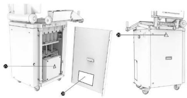
This pictogram indicates an electrocution hazard. Please isolate the machine before carrying out any work on it. You will find this pictogram inside the machine on the electrical enclosure (fig.14, n°27).
You will find the circuit diagram for the machine inside the left-hand door of the divider (fig.14, n°28).

This pictogram indicates a crushing hazard. Please isolate the machine before carrying out any work on it. You will find this pictogram on the side doors (fig.14, n°29).
5.4 Commissioning
Before commissioning, ensure that there are no extraneous objects interfering with the machine's moving parts.
Ensure first of all (after verifying electric compatibility) that the motor is rotating in the right direction. When the power is switched on, the green button flashes; press to start initialisation. If the heads do not rise during this stage and the indicator flashes rapidly, disconnect the plug and switch 2 phases in it.
For machine operation, refer to the "Operation" chapter.
5.5 Hazard
If the user or the machine is in danger, use the emergency stop to stop the machine.
Remove the plug from the mains socket before any maintenance and/or servicing work.
Any maintenance work or replacement of parts must be carried out by an approved agent.
6 CONTROLS AND SAFETY FEATURES
6.1 Controls
Your machine is equipped as standard with a mechanical control panel (fig.3).
6.2 Setting area
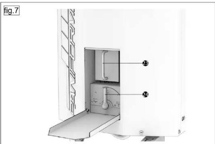
The pressure setting and flour recovery area is located at the front of the machine (fig.7), as well as the pressure time setting area and the half tank/full tank selector.
6.3 Work area
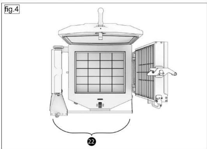
The work area is at the front of the machine (fig.4).

7 OPERATION
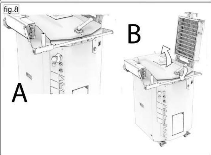
In-tank cutting operating procedure (DIV-R, TRADIFORM and PANIFORM only) (fig.8, 9)
A. Twist the emergency stop button (fig.3, n°16) ¼ turn to the right if it has not been activated.
B. Open the lid. (If the lid is difficult to open, please refer to chapter 10, Malfunctions).
C. Press the green button (fig. 3, n°21) if it flashes rapidly, to initialise the machine.
D. Choose the position of the heads (half tank or full tank) using the selector on the front.
E. If necessary, lightly flour the top of the heads in the tank
F. Empty the dough into the tank and spread it around roughly by hand.
G. If necessary, lightly flour the top of the dough.
H. You can adjust the tamping pressure using the pressure setting handle located on the front and the tamping time using the button on the front.
I. With the 10/20 option, you can choose between cutting into 10 or 20 divisions using the selector on the front.
J. Close the lid to raise the heads and divide the dough.
Never open the lid if the green button is not steadily lit.
K. When the green button lights up again, open the lid and collect the dough pieces.
L. Press the green button to start a new cycle.
The emergency stop button is used to stop a cycle in progress.
Dividing-moulding operating procedure (DIVIFORM, DIVIFORM+, TRADIFORM and PANIFORM)
(fig.10, 11)
A. Twist the emergency stop button (fig.3, n°16) ¼ turn to the right if it has not been activated.
B. (DIVIFORM+, TRADIFORM, PANIFORM) Open the lid and place the tamping plate at th
bottom of the tank (if the lid is difficult to open, please refer to chapter 10, Malfunctions).
Never use more than one tamping plate at a time. Do not stack multiple tamping plates in the tank.
C. Press the green button (fig. 3, n°21) if it flashes rapidly, to initialise the machine.
D. (TRADIFORM and PANIFORM) Choose the position of the heads (half tank or full tank) using the selector on the front.
E. If necessary, lightly flour the top of the of the coarse tamping plate.
F. Empty the dough into the tank and spread it around roughly by hand.
G. If necessary, lightly flour the top of the dough
H. (TRADIFORM and PANIFORM) You can adjust the tamping pressure using the pressure setting handle located on the front and the tamping time using the button on the front. (DIVIFORM+) You can adjust the tamping pressure using the pressure setting handle located on the side of the divider and the tamping time using the button on the front.
(DIVIFORM) Go to step K
- Close the lid to raise the heads and tamp the dough.
Never open the lid if the green button is not steadily lit.
J. When the green button lights up again, open the lid.
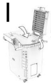
K. Close the frame to raise the heads and divide the dough.
L. When the green button lights up again, open the frame and collect the dough pieces.
M. Press the green button to start a new cycle.
The emergency stop button is used to stop a cycle in progress.
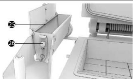
Easyflour flour dispenser filling procedure (fig.12)
A. Open the flour dispenser lid.
B. Empty the flour into the flour dispenser filling area (fig.12,n°25).
C. Close the flour dispenser lid.
D. Set the flour dispenser flow rate using the cursor (fig.12,n°26).
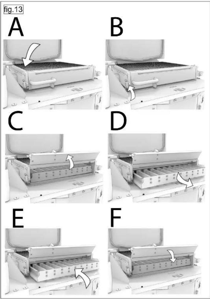
Click&Cut system grid changing procedure (fig.13)
A. Close the frame.
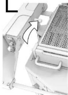
B. Open the grid compartment by releasing the catch on the left-hand side of the frame.
C. Close the grid compartment flap.
D. Remove the old grid.
E. Insert the new grid.
F. Close the grid compartment flap.
Machine reset procedure
A. Open the lid. If the lid is difficult to open, refer to chapter 10, Malfunctions.
B. Press the emergency stop button (fig.3, n°16).
C. Twist the emergency stop button (fig.3, n°16) ¼ tum to the right.
D. Press the flashing green button (fig.3, n°21).
8 MAINTENANCE
8.1 Daily, by a trained user
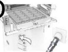
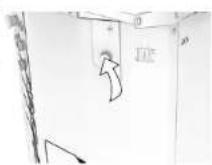
(fig.15)
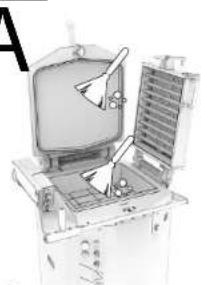
A. Place the heads and the knives in the lowered position and clean the tank and the lid.
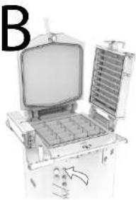
B. Press the knife cleaning button to raise the knives.
C. Activate the emergency stop, isolate the machine and clean the knives.
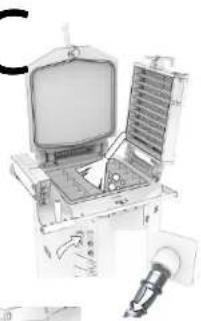
D. Release the emergency stop and reconnect the machine.
E. Press the green button to raise the heads and clean out dough and flour residues with a vacuum cleaner.
8.2 Weekly, by a trained user
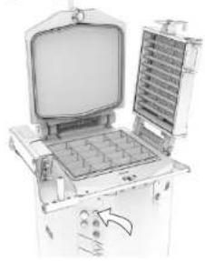
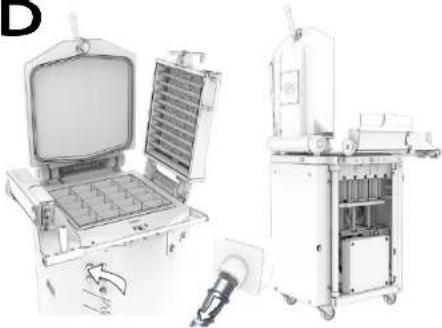
(fig.16)
A. Press the knife raise button to raise the knives.
B. Activate the emergency stop, isolate the machine and remove the side doors using a screwdriver.
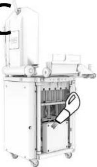
C. Using a vacuum cleaner, clean all over the inside of the machine as well as the mechanical components.
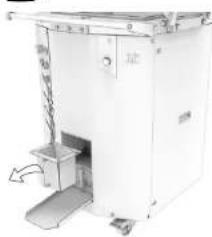
D. Refit the side doors and empty the flour recovery bin.
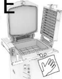
E. Wash the entire exterior with a damp cloth.
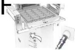
F. Release the emergency stop and reconnect the machine.
8.3 Six-monthly, by an approved agent
A. Place the heads in the lowered position.
B. Activate the emergency stop, isolate the machine and remove the right-hand side door using a screwdriver.
C. Check the oil level (the level must be between 4 and 5 cm from the top edge of the aluminium flange).
NOTE: Below you will find a non-exhaustive list of compatible hydraulic oils:
| CONDAT | HYDROLUB S46 |
| ELF | HYDRELF DS46 |
| CASTROL | AYSPIN AWS46 |
| TOTAL | AZOLLA ZS32 |
D. Release the emergency stop and reconnect the machine.
E. Check that your approved agent has recorded his work in order to maintain your 5-year warranty cover.
9 CONSUMABLES
When ordering spare parts, check with your approved agent which part is required based on the spare parts catalogue issued by the manufacturer.
Always specify the machine serial number as shown on the nameplate.
Your agent will place the orders with JAC.
9.1 List of CONSUMABLES
| ITEM CODE | NEW DESCRIPTION | MODEL |
| F1500009 | LID SEAL | DIV-R, TRADIFORM, PANIFORM |
| F1500004 | LID SPRING NG | DIV-R, DIVIFORM+, TRADIFORM, PANIFORM |
| F1513364 | CLICK&CUT SPRING RH | DIVIFORM, DIVIFORM+, TRADIFORM, PANIFORM |
| 10040012 | WEAR PLATE | DIV-R, DIVIFORM+, TRADIFORM, PANIFORM |
| HUILEHYDROS46 | CONDAT HYDRAULIC OIL S46 | ALL |
| F140000311 | DOUBLE EXCENTRIC | DIV-R, DIVIFORM+, TRADIFORM, PANIFORM |
| F1513326 | LOCK PIN | DIVIFORM, DIVIFORM+, TRADIFORM, PANIFORM |
10 MALFUNCTIONS
NB: The machine must be isolated from the power supply before attempting any work on it.
| Problem | Check |
| Problem 1: The machine will not start | Open the lid immediately so that the dough is not left fermenting in the tank. (If the handle is difficult to open by hand, refer to Problem 7).Check the main power supply and the power supply to the motor.Check whether the thermal cut-out has tripped. |
| Problem 2: The hydraulic power pack starts up but the heads will not rise | Switch two phases on the machine plug. |
| Problem 3: Machine lacks power | Check oil level. The level must be between 4 and 5 cm from the top edge. |
| Problem 4: The heads rise but the knives do not extend | Contact your technician. |
| Problem 5: Oil on the floor | Contact your technician. |
| Problem 6: The green button flashes rapidly | Press the green button (fig. 3, n°21).Open the lid (if the handle is difficult to open by hand, refer to Problem 7).If the green button continues to flash rapidly, activate the emergency stop and refer to Problem 8. |
| Problem 7: The lid cannot be opened, orThe dough has been left unsupervised in the closed tank | Do not try to force the lid open. Only one person should handle the machine.Do not use a tool to force the lid open.If dough has fermented in the tank for more than a few minutes, be careful when trying to open the lid. Keep away from the line of opening of the lid.If the lid cannot be opened in accordance with the user instructions, please contact your technician. Keep away from the line of opening of the lid until the technician arrives. |
| Problem 8: The emergency stop button has been pressed | 1. If the lid is open:Twist the mushroom button (emergency stop) (fig.3, n°16) 14 turn to the right.Press the green button (fig. 3, n°21) to reset the machine.2. If the lid is closed:Twist the mushroom button (emergency stop) (fig.3, n°16) 14 turn to the right.Press the green button (fig. 3, n°21).Open the lid (if the handle is difficult to open by hand, refer to Problem 7).Press the green button (fig. 3, n°21) to reset the machine. |
| Problem 9: In the event of a power cut | Open the lid immediately so that the dough is not left fermenting in the tank. (If the handle is difficult to open by hand, refer to Problem 7). |

Should the problem persist, please contact your technician.
11 LIST OF COMPONENTS IN ILLUSTRATIONS
| Figure | Item | Description |
| 1 | 1 | Lid |
| 2 | Lid seal | |
| 3 | Easyflour flour dispenser | |
| 4 | Tank | |
| 5 | Heads | |
| 6 | Flour recovery | |
| 7 | Easyflour flour dispenser guide rail | |
| 8 | Braked castors | |
| 9 | Lid closing handle | |
| 10 | Lid closing eccentric | |
| 11 | Easylock grid mount closing system | |
| 12 | Grid frame | |
| 13 | Door handle | |
| 14 | Pressure setting compartment | |
| 2 | 15 | Knives |
| 3 | 16 | Emergency stop |
| 17 | Pressure time | |
| 18 | Knife cleaning | |
| 19 | Half tank/full tank | |
| 20 | 10/20 selection button (10/20 option) | |
| 21 | Green button and condition indicator | |
| 4 | 22 | Work area |
| 7 | 23 | Flour recovery bin |
| 24 | Pressure setting | |
| 12 | 25 | Easyflour flour dispenser filling area |
| 26 | Easyflour flour dispenser flow rate setting cursor | |
| 14 | 27 | Pictogram indicating an electrocution hazard |
| 28 | Circuit diagram | |
| 29 | Pictogram indicating a crushing hazard |
Français
1 AVANT LA MISE EN SERVICE 18
2 GARANTIE....18
3 AVERTISSEMENTS....19
4 CARACTERISTIQUES TECHNIQUES....20
Plaque tasse-gras : PE-UHMW

5 INSTALLATION ET MISE EN SERVICE
Messer: Edelstahl 304
Deckel: Aluminium AlSi10Mg
golden hard anodizing (GHA)
A_1=1
زی ۱۰۶.
الهلا لكي دون عطاب
جَدَابِّاً بِمْرَةٍ
البانيالجها
طلا تانج ! حا
8.3
(二)公司简介
A!
زی دع متن
مُحْلَّهِ مُحْلَّهِ مُحْلَّهِ دُمُو لَا أَرْ قَيْطَدٍ لَةٍ يُو لَعْلٍ ١٤ٍ فَأَحْلٍ ١٤ٍ نَ 54
الغَلَّمَةِ كُمْعَلَةٍ كُمْدُ لورَدِيْهُ لَانْتَوَيْزِ لَبَةٍ بِحُرُ وَ
| CONDAT | HYDROLUB S46 |
| ELF | HYDRELF DS46 |
| CASTROL | AYSPIN AWS46 |
| TOTAL | AZOLLA ZS32 |
55
طلاةً، دجها
[Unreadable]

[Unreadable]
Δ22
.JAC

| ### | ### | ### |
| DIV-R, TRADIFORM, PANIFORM | ### | F1500009 |
| DIV-R, DIVIFORM+, TRADIFORM, PANIFORM | ### | F1500004 |
| DIVIFORM, DIVIFORM+, TRADIFORM, PANIFORM | ### | F1513364 |
| DIV-R, DIVIFORM+, TRADIFORM, PANIFORM | ### | 10040012 |
| ### | CONDAT S### | HUILEHYDROS46 |
| DIV-R, DIVIFORM+, TRADIFORM, PANIFORM | ### | F140000311 |
| DIVIFORM, DIVIFORM+, TRADIFORM, PANIFORM | ### | F1513326 |
140511x
العربية
| وَقْحَاتَا | الكُمْنَا | |
| صُها جَمْضَهِ يَكُانِال٠٦ | ٥١٢٣٤٥١٢٢٢٢٢٢٢٢٢٢٢٢٢٢٢٢٢٢٢٢٢٢٢٢٢٢٢٢٢٢٢٢٢٢٢٢٢٢٢٢٢٢٢٢٢٢٢٢٢٢٣٥١٢٢٢٢٢٢٢٢٢٢٢٢٢٢٢٢٢٢٢٢٢٢٢٢٢٢٢٢٢٢٢٢٢٢٢٢٢٢٢٢٢٢٢٢٢٢٢٣٥٢٢٢٢٢٢٢٢٢٢٢٢٢٢٢٢٢٢٢٢٢٢٢٢٢٢٢٢٢٢٢٢٢٢٢٢٢٢٢٢٢٢٢٢٢٢٢٢٢٩١٢٢٢٢٢٢٢٢٢٢٢٢٢٢٢٢٢٢٢٢٢٢٢٢٢٢٢٢٢٢٢٢٢٢٢٢٢٢٢٢٢٢٢٢٢٢٢٢٣٠٢٢٢٢٢٢٢٢٢٢٢٢٢٢٢٢٢٢٢٢٢٢٢٢٢٢٢٢٢٢٢٢٢٢٢٢٢٢٢٢٢٢٢٢٢٢٢٢٢١٢٢٢٢٢٢٢٢٢٢٢٢٢٢٢٢٢٢٢٢٢٢٢٢٢٢٢٢٢٢٢٢٢٢٢٢٢٢٢٢٢٢٢٢٢٢٢٢١١٢٢٢٢٢٢٢٢٢٢٢٢٢٢٢٢٢٢٢٢٢٢٢٢٢٢٢٢٢٢٢٢٢٢٢٢٢٢٢٢٢٢٢٢٢٢٢٢٩٠٢٢٢٢٢٢٢٢٢٢٢٢٢٢٢٢٢٢٢٢٢٢٢٢٢٢٢٢٢٢٢٢٢٢٢٢٢٢٢٢٢٢٢٢٢٢٢٢٣١٢٢٢٢٢٢٢٢٢٢٢٢٢٢٢٢٢٢٢٢٢٢٢٢٢٢٢٢٢٢٢٢٢٢٢٢٢٢٢٢٢٢٢٢٢٢٢٢٨١٢٢٢٢٢٢٢٢٢٢٢٢٢٢٢٢٢٢٢٢٢٢٢٢٢٢٢٢٢٢٢٢٢٢٢٢٢٢٢٢٢٢٢٢٢٢٢٢٧١٢٢٢٢٢٢٢٢٢٢٢٢٢٢٢٢٢٢٢٢٢٢٢٢٢٢٢٢٢٢٢٢٢٢٢٢٢٢٢٢٢٢٢٢٢٢٢٢٦١٢٢٢٢٢٢٢٢٢٢٢٢٢٢٢٢٢٢٢٢٢٢٢٢٢٢٢٢٢٢٢٢٢٢٢٢٢٢٢٢٢٢٢٢٢٢٢٢٤١٢٢٢٢٢٢٢٢٢٢٢٢٢٢٢٢٢٢٢٢٢٢٢٢٢٢٢٢٢٢٢٢٢٢٢٢٢٢٢٢٢٢٢٢٢٢٢٢٥١٢٢٢٢٢٢٢٢٢٢٢٢٢٢٢٢٢٢٢٢٢٢٢٢٢٢٢٢٢٢٢٢٢٢٢٢٢٢٢٢٢٢٢٢٢٢٢٩١١٢٢٢٢٢٢٢٢٢٢٢٢٢٢٢٢٢٢٢٢٢٢٢٢٢٢٢٢٢٢٢٢٢٢٢٢٢٢٢٢٢٢٢٢٢٢٢٣١١٢٢٢٢٢٢٢٢٢٢٢٢٢٢٢٢٢٢٢٢٢٢٢٢٢٢٢٢٢٢٢٢٢٢٢٢٢٢٢٢٢٢٢٢٢٢٢٩٠١٢٢٢٢٢٢٢٢٢٢٢٢٢٢٢٢٢٢٢٢٢٢٢٢٢٢٢٢٢٢٢٢٢٢٢٢٢٢٢٢٣١١٢٢٢٢٢٢٩١١٢٢٢٢٢٢٩١١٢٢٢٢٩١١٢٢٩١١٢٩١١٢٩١١٢٩١١٢٩١١٢٩١١٢٩١١٢٩١١٢٩١١٢٩١١٢٩١١٢٩١١٢٩١١٢٨١١٢٩١١٢٩١١٢٩١١٢٩١١٢٩١١٢٩١١٢٩١١٢٩١١٢٩١١٢٩١١٢٩١١٢٩١٠ ۱, دِرَجِيَ الَىِيِ المِشْتَلَةِ رَفْم ۱. | |
fig.2
natural_image
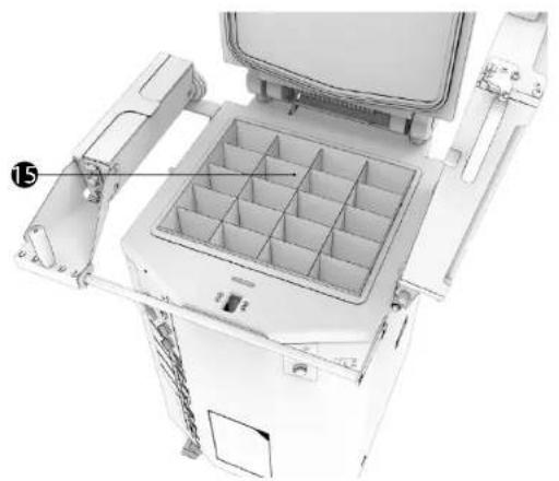
3D rendering of a mechanical device with internal compartments and mounting brackets (no visible text or symbols)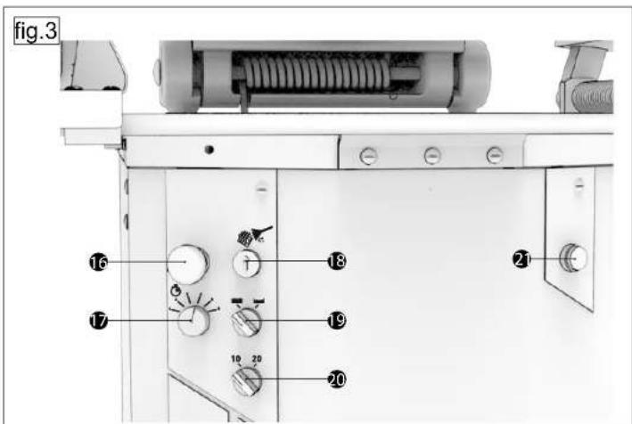
natural_image
Technical line drawing of a mechanical device with internal grid and cooling fins (no text or symbols)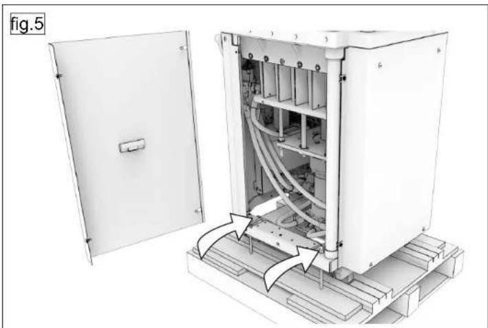
natural_image
Technical illustration of an electrical enclosure with visible wiring and components, no text or symbols present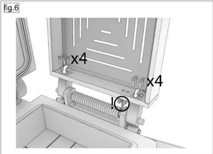
natural_image
Technical line drawings of industrial equipment components labeled A and B, showing internal structures and mounting features (no text or symbols beyond labels)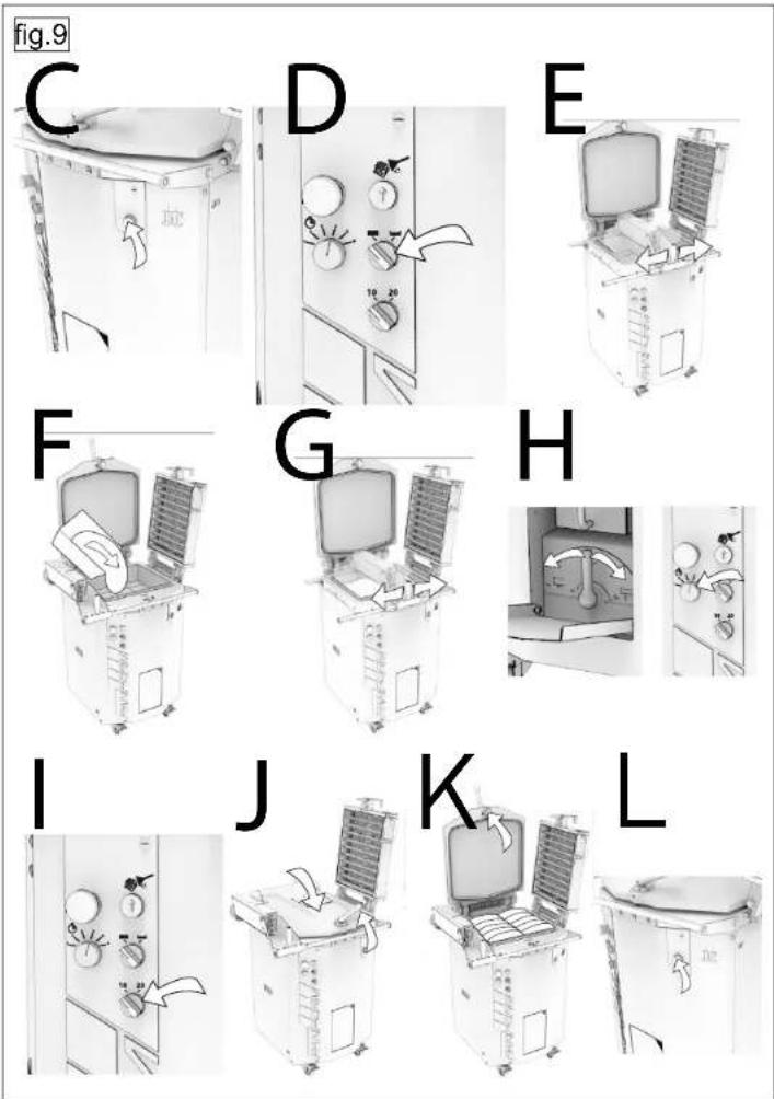
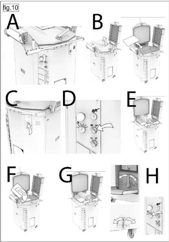
fig.11
natural_image
Illustration of a laboratory instrument with a rack-mounted unit and directional arrows indicating motion (no text or symbols)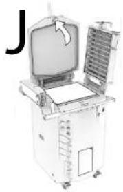
natural_image
Illustration of a medical or laboratory device with an open screen and ventilation slots, no visible text or symbols.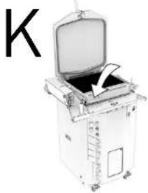
natural_image
Illustration of a medical or laboratory device with open lid and internal components (no visible text or symbols)L
natural_image
Close-up of a mechanical device with a mesh grille and directional arrow (no visible text or symbols)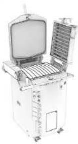
natural_image
Illustration of an open industrial machine with a central panel and control panel (no visible text or symbols)M
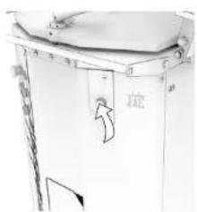
fig.12
113
fig.14
natural_image
Technical line drawings of industrial equipment components, showing front, side, and top views with no visible text or symbols.fig.15
A
natural_image
Illustration of a computer monitor with an open screen and a pencil, showing no text or symbols.B
natural_image
Illustration of an open laboratory machine with a computer screen and internal grid array (no text or symbols visible)C
natural_image
Illustration of an open electronic device with a monitor and control panel (no visible text or symbols)D
E
114
fig.16
A
natural_image
Illustration of a vintage computer setup with open screen and internal grid device (no text or symbols visible)B
natural_image
Two views of a medical or laboratory device with open and closed sections, no visible text or symbols.C
natural_image
Industrial machine with mechanical components and a hand inserting a component (no visible text or symbols)D
natural_image
Exterior view of a white industrial machine with cooling unit and side-mounted door (no visible text or symbols)E
natural_image
Illustration of an open laptop computer with a hand gesture overlay (no text or symbols)F
natural_image
Close-up of a mechanical device with a grid-patterned panel and directional arrow (no visible text or symbols)
Traditionally Innovative
CONFORMITY DECLARATION TO THE EUROPEAN DIRECTIVES.
DECLARATION DE CONFORMITE AUX DIRECTIVES EUROPEENNES.
KONFORMITÄTSERKLÄRUNG AN DEN EUROPÄISCHEN RICHTLINIEN. VERKLARING VAN OVEREENSTEMMING MET DE EUROPESE RICHTLIJNEN.
The undersigned declares that the machine complies with the European Directives 2006/42/CE. 2014/35/UE. 2014/30/UE.
FR
Complies with the following (parts of)
European Harmonised Standards: EN 1570.3
EN 1072-2 100510004
EN ISO 12100-1
EN ISO 12100-2 65.66
EN 13954 if applicable
Technical files compiled by:
Chief Executive Officer
JAG s.a

- BEFORE COMMISSIONING
- WARRANTY
- All JAC products are covered by a 5-year warranty.
- Subject to the following restrictive conditions:
- WARNINGS
- TECHNICAL SPECIFICATIONS
- Details of materials in direct contact with dough
- INSTALLATION AND COMMISSIONING
- Unpacking the machine
- Location
- Electrical connection
- Commissioning
- Hazard
- CONTROLS AND SAFETY FEATURES
- Controls
- Setting area
- Work area
- OPERATION
- MAINTENANCE
- Daily, by a trained user
- Weekly, by a trained user
- Six-monthly, by an approved agent
- CONSUMABLES
- Français
- INSTALLATION ET MISE EN SERVICE
- Traditionally Innovative
Brand : JAC
Model : DIVR
Category : Pasta machine