
HMK 90A3 MS SP BK - Basket Master Kitchen - Free user manual and instructions
Find the device manual for free HMK 90A3 MS SP BK Master Kitchen in PDF.

User questions about HMK 90A3 MS SP BK Master Kitchen
0 question about this device. Answer the ones you know or ask your own.
Ask a new question about this device
Download the instructions for your Basket in PDF format for free! Find your manual HMK 90A3 MS SP BK - Master Kitchen and take your electronic device back in hand. On this page are published all the documents necessary for the use of your device. HMK 90A3 MS SP BK by Master Kitchen.
USER MANUAL HMK 90A3 MS SP BK Master Kitchen
natural_image
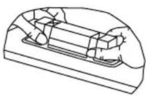
Technical line drawing of a cabinet or enclosure assembly with mounting base (no text or symbols)
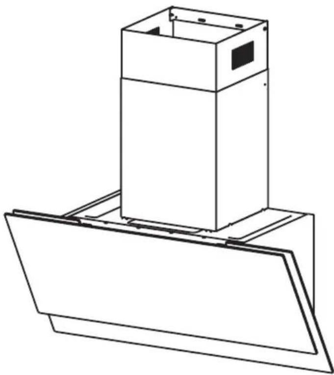
The instructions for Use apply to several versions of this appliance. Accordingly, you find descriptions of individual features that do not apply to your specific appliance.
INSTALLATION
- The manufacturer will not be held liable for any damages resulting from incorrect or improper installation.
- The minimum safety distance between the cooker top and the extractor hood is 650 mm (some models can be installed at a lower height, please refer to the paragraphs on working dimensions and installation).
- Check that the mains voltage corresponds to that indicated on the rating plate fixed to the inside of the hood.
- For Class I appliances, check that the domestic power supply guarantees adequate earthing.
- Connect the extractor to the exhaust flue through a pipe of minimum diameter 120mm. The route of the flue must be as short as possible.
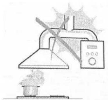
- Do not connect the extractor hood to exhaust ducts carrying combustion flumes (boilers, fireplaces, etc.).
- If the extractor is used in conjunction with non-electrical appliances (e.g. gas burning appliances), a sufficient degree of aeration must be guaranteed in the room in order to prevent the backflow of exhaust gas. The kitchen must have an opening communicating directly with the open air in order to guarantee the entry of clean air. When the cooker hood is used in conjunction with appliances supplied with energy other than electric, the negative pressure in the room must not exceed 0,04 mbar to prevent fumes being drawn back into the room by the cooker hood.
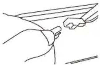
- In the event of damage to the power cable, it must be replaced by the manufacturer or by the technical service department, in order to prevent any risks.
- If the instructions for installation for the gas hob specify a greater distance specified above, this has to be taken into account. Regulations concerning the discharge of air have to be fulfilled.
USE
- The extractor hood has been designed exclusively for domestic use to eliminate kitchen smells.
- Never use the hood for purposes other than for which it has been designed.
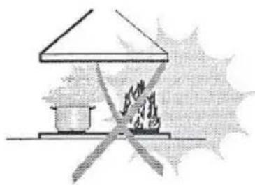
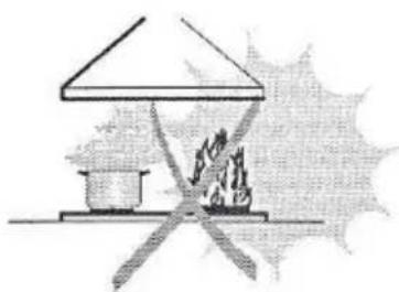
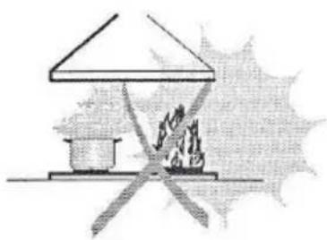
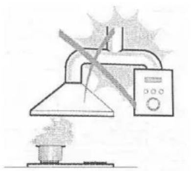
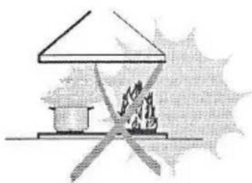
● Never leave high naked flames under the hood when it is in operation. - Adjust the flame intensity to direct it onto the bottom of the pan only, making sure that it does not engulf the sides.
- Deep fat fryers must be continuously monitored during use: overheated oil can burst into flames.
- Do not flame under the range hood; risk of fire.
- This appliance can be used by children aged from 8 years and above and persons with reduced physical, sensory or mental capabilities or lack of experience and knowledge if they have been given supervision or instruction concerning use of the appliance in a safe way and understand the hazards involved.
● Children should be supervised to ensure that they do not play with the appliance.
● Cleaning and user maintenance shall not be made by children without supervision. - "CAUTION: Accessible parts may become hot when used with cooking appliances".
MAINTENANCE
- Switch off or unplug the appliance from the mains supply before carrying out any maintenance work.
- Clean and/or replace the Filters after the specified lime period (Fire hazard).
- Clean the hood using a damp cloth and a neutral liquid detergent.
● The ap pliance uses 4 hob elements at most.

The symbol ■ is packaging indicates that this product may not be treated as household waste. Instead it shall be handed over to the applicable collection point for the recycling of electrical and electronic equipment. By ensuring this product is disposed of correctly, you will help prevent potential negative consequences for the environment and human health, which could otherwise be caused by inappropriate waste handling of this product. For more detailed information about recycling of this product, please contact your local city office, your household waste disposal service or the shop where you purchased the product.
natural_image
Simple line drawing of a laboratory setup with a conical flask, heating element, and control panel (no text or symbols)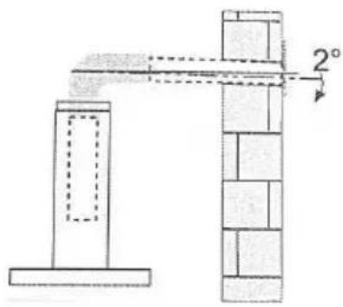
natural_image
Simple line drawing of a house with a stove and fire, no text or symbols present| Ref. | Qty. | Product Components |
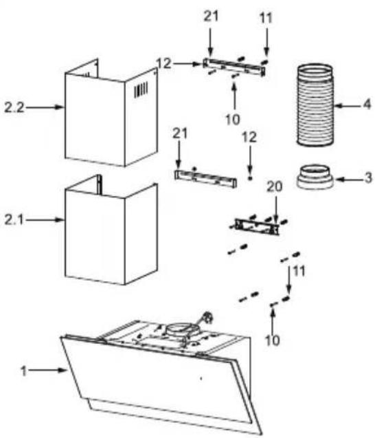
| 1 | 1 | Hood Body, complete with: Controls, Light, Blower, Filter. |
| 2.1 | 1 | Lower Decorative Chimney (optional) |
| 2.2 | 1 | Upper Decorative Chimney (optional) |
| 3 | 1 | Flange (optional) |
| 4 | 1 | Exhaust Pipe |
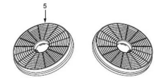
| 5 | 2 | The Activated Charcoal filter (optional) |
| Ref. Qty. Installation Components | ||
| 10 | 7 | Screws 5 x 50 |
| 11 | 7 | Wall Plugs |
| 12 | 6 | Screws 4.2 x 9.5 |
| 20 | 1 | Hood fixing bracket ( optional ) |
| 21 | 2 | Chimney fixing bracket (0/1 optional ) |
| Qty. Documentation | |
| 1 | Instruction Manual |
natural_image
Two circular mechanical components with radial grooves, one labeled with a number 5 (no text or symbols on the components themselves)
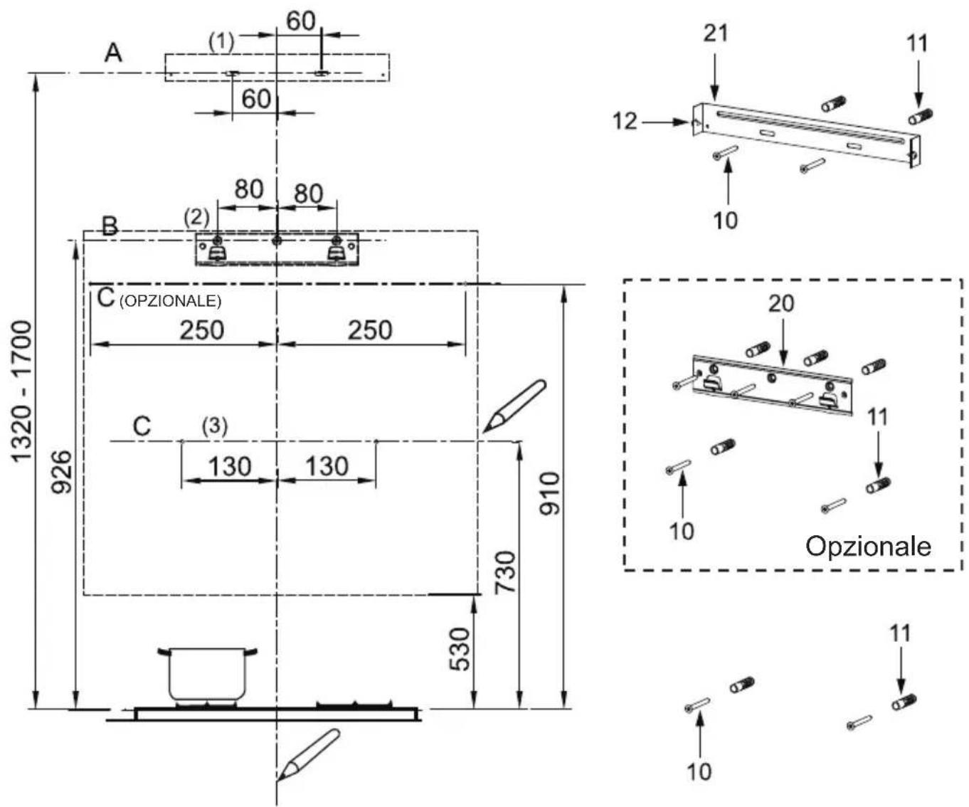
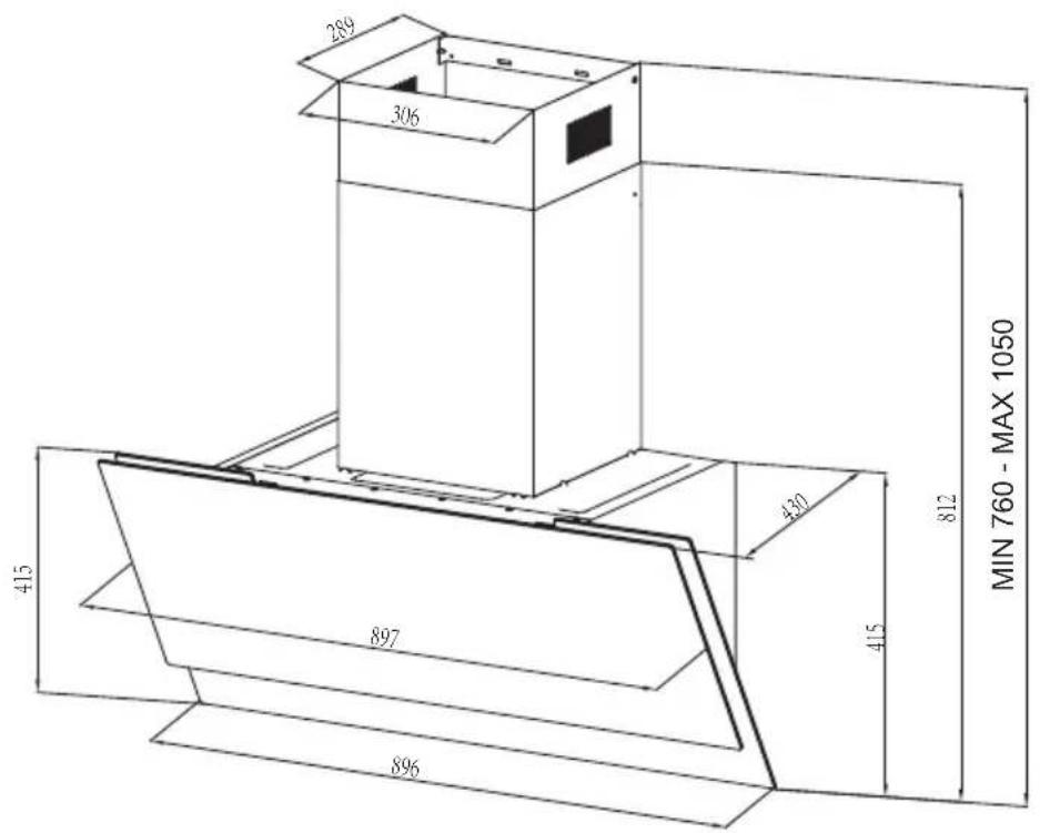
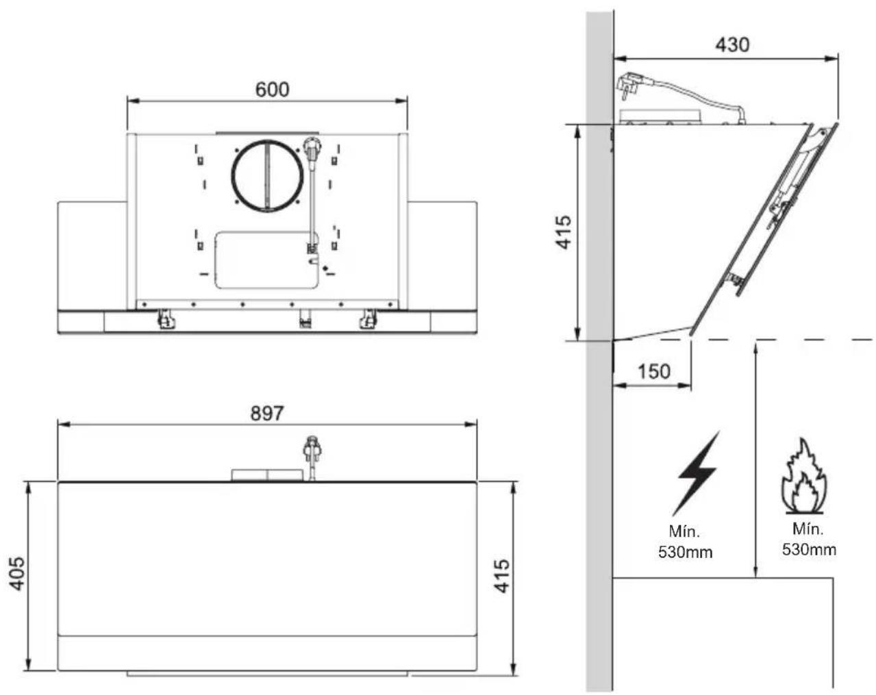
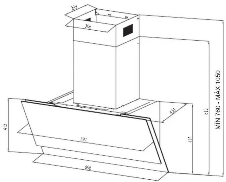
unit:mm
WALL DRILLING AND BRACKET FIXING
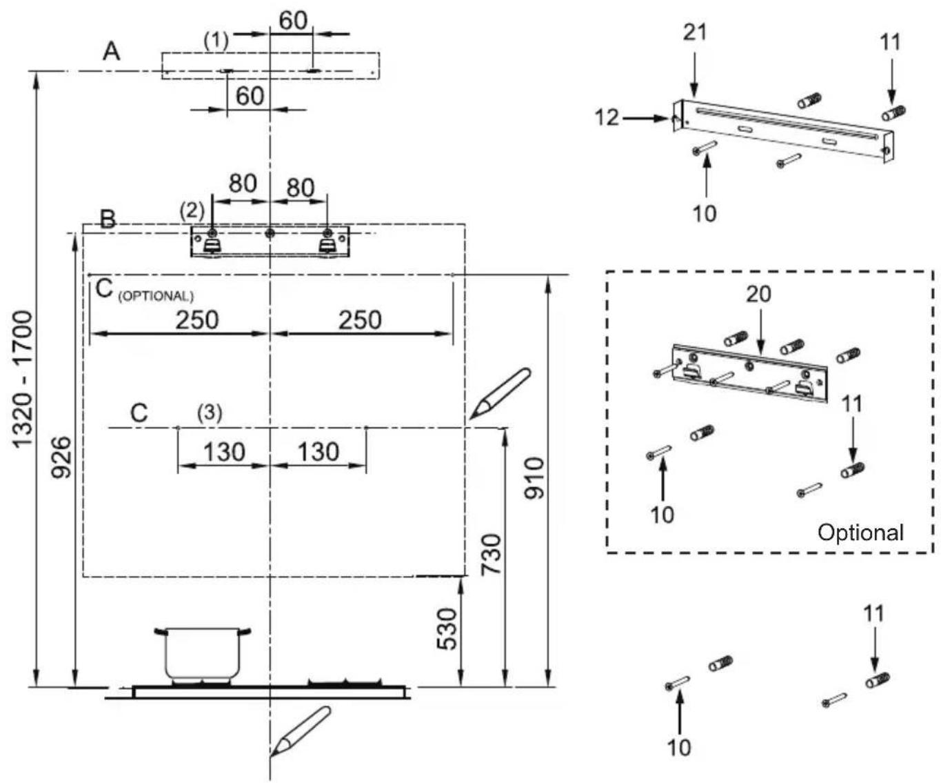
As a first step, proceed with the following drawings:
- A vertical line up to the ceiling or up to the upper limit, at the center of the area in which the hood is to be fitted.
- A horizontal line A at 1320 – 1700 mm above the cooker top.
- A horizontal line B at a minimum 926 mm above the cooker top.
- A horizontal line C at a minimum 730 (910 optional) mm above the cooker top.
Mark Points:
- Mark a point (1) on the horizontal line A, 60 mm to the right of the vertical reference line.
- Repeat this operation on the other side, checking that the two marks are leveled.
- Mark a point (2) on the horizontal line B, 80 mm to the right of the vertical reference line.
-
Repeat this operation on the other side and on the vertical reference line, checking that the three marks are leveled.
-
Mark a point (3) on the horizontal line C, 130 (250 optional) mm to the right of the vertical reference line.
- Repeat this operation on the other side, checking that the two marks are on the same horizontal line.
Fix the brackets (Optional):
- Drill at the marked points (1) (2) (3), using a 10 mm drill bit.
- Insert the Wall Plugs 11 into the holes (1) (2) (3).
- Fix the hood fixing bracket 20 with 3 screws 10 (5 x 50) supplied with the hood.
- Fix a Chimney fixing bracket 21 with 2 screws 10 (5 x 50) supplied with the hood.
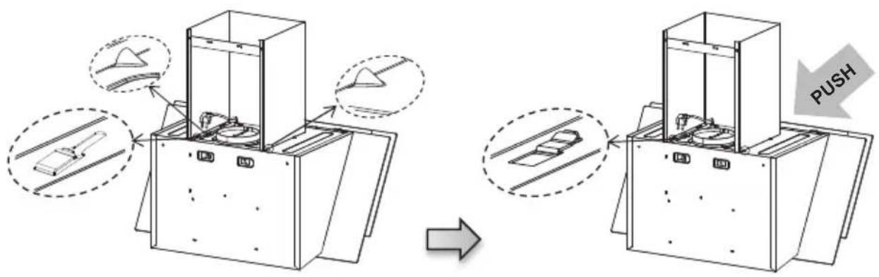
Hook the hood body:
- Open the panel.
- Remove the Metal grease filter using the handles provided.
- Hook the hood body to the bracket 20.
- Level the hood body itself.
natural_image
Simple line drawing of a blank rectangular frame with no text, numbers, or symbols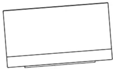
natural_image
Simple line drawing of a rectangular frame with a horizontal divider (no text or symbols)Right Wrong
- From the inside of the hood body, fix the screws 10 to Wall Plugs 11 at the points (3).
• Fit the filter into the hood. - Close the panel.
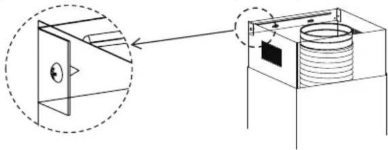
CONNECTIONS
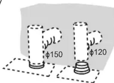
DUCTED VERSION AIR EXHAUST SYSTEM
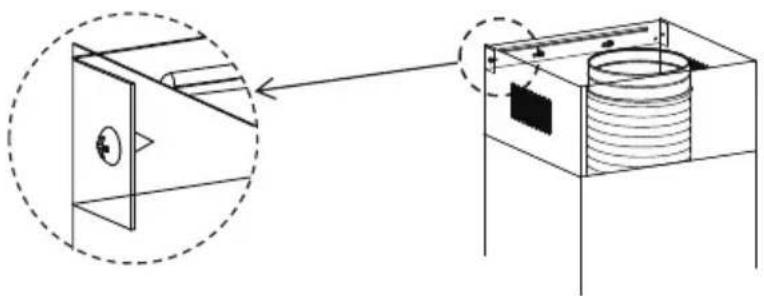
When installing the ducted version, connect the hood to the chimney using either a flexible or rigid pipe 150 or 120 mm, the choice of which is left to the installer.
- To install a 120 mm air exhaust connection, insert the reducer flange 3 on the hood body outlet.
- Fix the pipe 4 in position using sufficient pipe clamps (not supplied).
- Remove possible charcoal filters.
The chimney can only be installed with exhausting hood.
Lower Decorative Chimney
- Fix a Chimney fixing bracket 21 onto the Lower Decorative Chimney with 2 screws 12 (4.2 x 9.5) supplied with the hood.
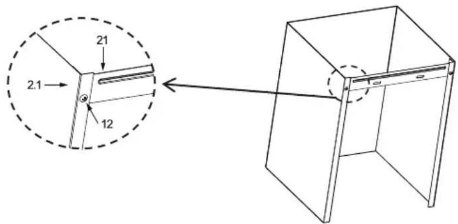
- Slightly widen the two sides of the flue and hook them onto the hood body, making sure that they are well seated.
Upper Decorative Chimney
- Slightly widen the two sides of the upper chimney and hook them between the wall and the bracket 21 which is fixed on the Lower Decorative Chimney.
- Fix the upper chimney onto the bracket 21 with 2 screws 12 (4.2 x 9.5) supplied with the hood.
natural_image
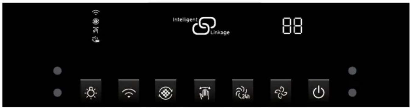
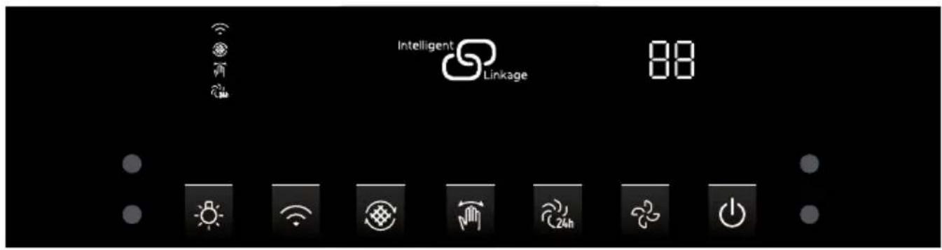
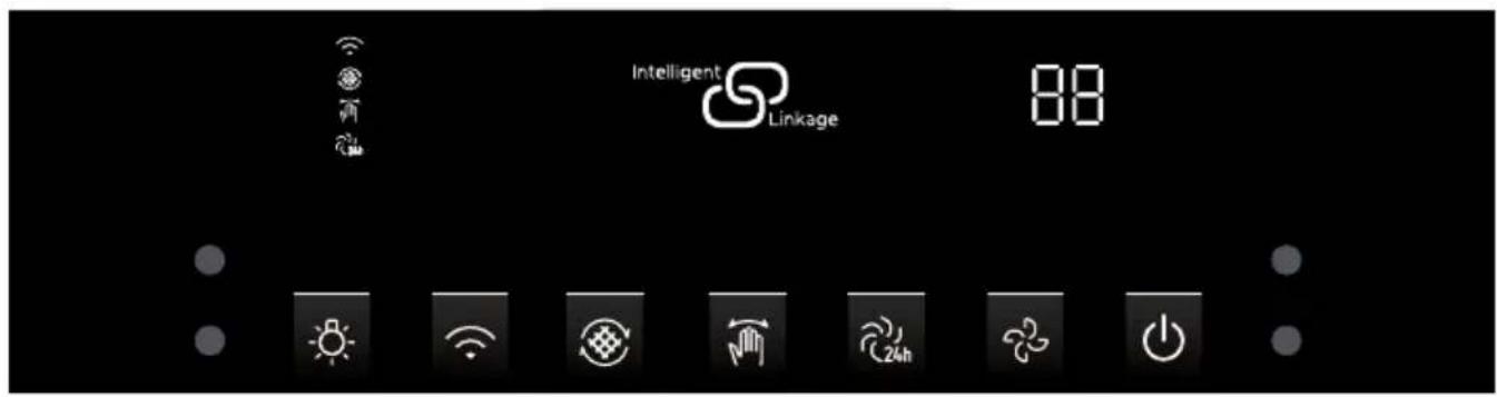
Technical diagram showing a mechanical assembly with a dashed circular inset view of a cabinet or housing (no text or symbols present)CONTROL PANEL
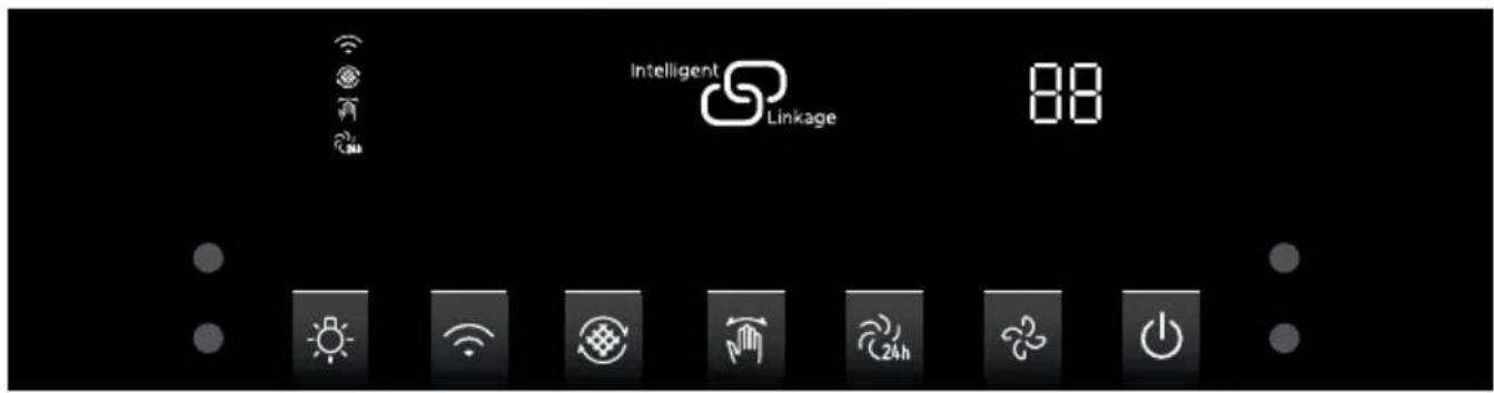
| Button Name Function | ||
 | Light | Short press: Turn on/off the light. |
 | Connect | Long press: Turn on the WLAN function; Long press + short press: Turn off the WLAN function (When flash slowly) |
 | Filter clean reminder | Turn on the function, The button flash to remind cleaning filter when the fan has been running 150 hours. |
 | Gesture | Short press: turn on/off the gesture control. |
 | Air refresh | Turn on the function, The fan runs 15 minutes every 24 hours in low speed. |
 | Speed | Short press: Adjust speed. |
 | Switch | 1st Short press: Startup (03 speed); 2nd Short press: Delay 3 min; 3rd Short press: Standby mode; 4th Short press:OFF immediately. |
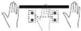
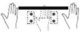 | Wave hand from left to right in stand by status to turn on theproduct. The default speed is the last speed set by user. Default speed is the 03 speed at the first switch on. In running state, waving hand to the left side to enter the delay off state for 3 minutes. Waving hand to the right side to switch speed (01-02-03-0b-01) repeatedly. | |
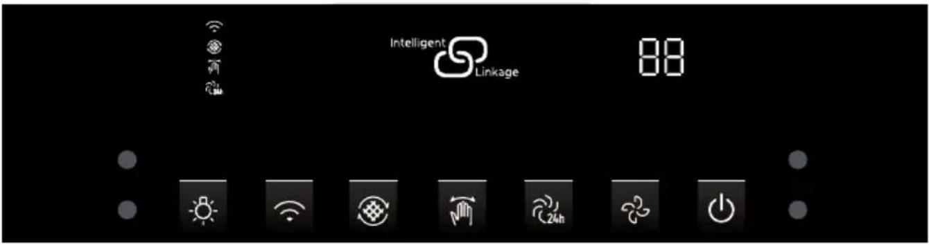
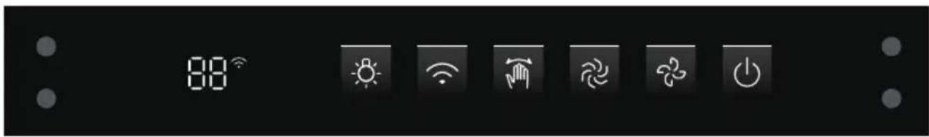
CONTROL PANEL
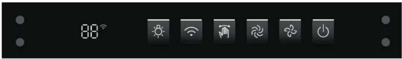
| Button Name Function | ||
 | Short press: Turn on/off the light.Light | |
 | Connect | Long press: Turn on the WLAN function;Long press + short press: Turn off the WLAN function (When flash slowly) |
 | Gesture | Short press: turn on/off the gesture control. |
 | Boost | Short press: Startup (0b speed),return to 03 speed after 8 min. please select manually if needs it to continue |
 | Speed | Short press: Adjust speed. |
 | Switch | 1st Short press: Startup (03 speed);2nd Short press: Delay 3 min;3rd Short press: Standby mode;4th Short press:OFF immediately. |
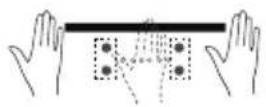
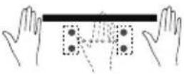 | Wave hand from left to right in stand by status to turn on theproduct. The default speed is the last speed set by user. Default speed is the 03 speed at the first switch on. In running state, waving hand to the left side to enter the delay off state for 3 minutes. Waving hand to the right side to switch speed (01-02-03-0b-01) repeatedly. | |
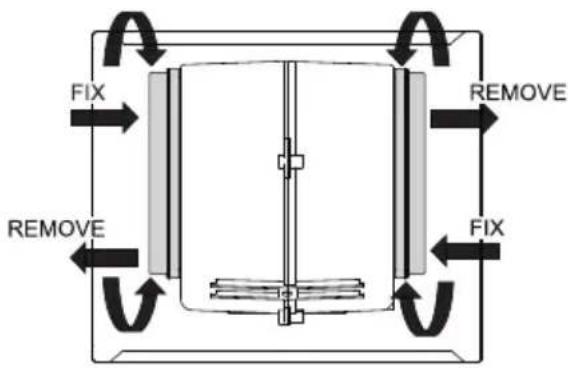
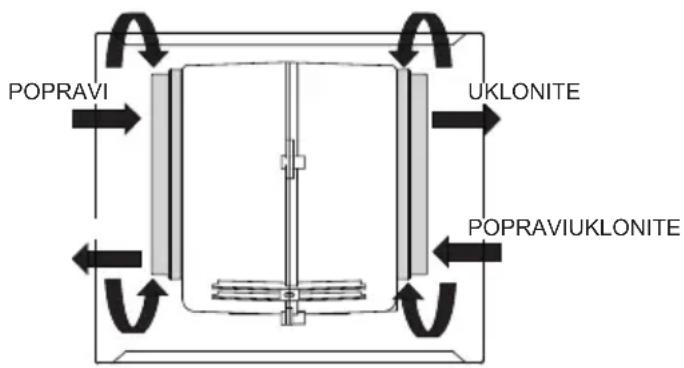
GREASE FILTERS
CLEANING METAL SELF-SUPPORTING GREASE FILTERS
- The filters must be cleaned every 2 months of operation, or more frequently for particularly heavy usage, and can be washed in a dishwasher.
- Pull the comfort panels to open them.
- Remove the filters one by one pushing them towards the back side of the hood unit and simultaneously pulling downwards.
- Any kind of bending of the filters has to be avoided when washing them. Before fitting them again into the hood make sure that they are completely dry. (The color of the filter surface may change throughout the time but this has no influence to the filter efficiency).
- When fitting the filters into the hood pay attention that they are mounted in correct position the handle facing outwards.
- Close the comfort panel.
natural_image
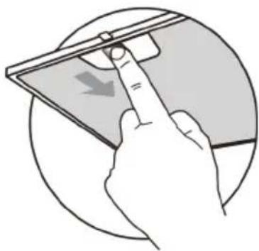
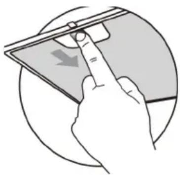
Illustration of a hand holding a tablet with a downward arrow, enclosed in a circular frame (no text or symbols)ACTIVATED CHARCOAL FILTER (RECIRCULATION VERSION)
These filters are not washable and cannot be regenerated, and must be replaced approximately every 4 months of operation, or more frequently with heavy usage.
REPLACING THE ACTIVATED CHARCOAL FILTER
- Open the comfort panels pulling them downwards.
- Remove the metal grease filters
- Remove the saturated activated charcoal filter.
- Fit the new filters.
- Replace the metal grease filters.
- Close the comfort panel
DISPOSAL OF OLD ELECTRICAL APPLIANCES
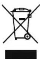
The European directive 2012/19/EU on Waste Electrical and Electronic Equipment (WEEE), requires that old household electrical appliances must not be disposed of in the normal unsorted municipal waste stream. Old appliances must be collected separately in order to optimize the recovery and recycling of the materials they contain, and reduce the impact on human health and the environment.
The crossed out "wheeled bin" symbol on the product reminds you of your obligation, that when you dispose of the appliance, it must be separately collected.
Consumers should contact their local authority or retailer for information concerning the correct disposal of their old appliance.
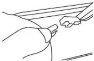
LIGHT REPLACEMENT
- Switch off the extractor hood and isolate the extractor hood by pulling out the mains plug or switching off the fuse.
- Remove the grease filter.
- Remove the light by levering its fitting from the hood body(this may require pressure or force to be applied).
| Max power | Voltage | Picture | Lamp Cap | ILCOS D code | |
| LED modules separate ballast | 1.5W | DC 12 V |  Diameter:33.2mmx120mm Diameter:33.2mmx120mm | / | DSS-1.5-S-33.2/120 |
natural_image
Line drawing of a mechanical component with no visible text or symbols
natural_image
Technical line drawing of a mechanical component with a curved top and rectangular base (no text or symbols)- Disconnect the connector of the light.
- Replace the light with a new one of the same type, making sure that you connect the light with the light cable correctly.
- Reinstall the light back to the hood body.
natural_image
Line drawing of a hand holding a tool, no text or symbols present| Fault | Cause | Solution |
| Light on, but motor does not work | The blades are blocked. | |
| The capacitor is damaged. | Replace capacitor. | |
| The motor is damaged. | Replace motor. | |
| The internal wiring of motor is cut off/disconnected. An unpleasant smell may be produced. | Replace motor. | |
| Both light and motor do not work | Apart from the above mentioned, check the following: | |
| Light damaged. | Replace lights. | |
| Power cord loose. | Connect the wires as per the electric diagram. | |
| Oil leakage | Outlet and the air ventilation entrance are not tightly sealed. | Take down the outlet and seal with glue. |
| Leakage from the connection of U-shaped section and cover. | Take U-shaped section down and seal with soap or paint. | |
| Vibration | The blade, if damaged, can cause vi brating. | Replace the blade. |
| The motor is not tightly fastened. | Fasten the motor tightly. | |
| The cooker hood is not tightly fixed. | Fixed the cooker hood tightly. | |
| Insufficient suction | The distance between the cooker hood and the cooker top is too large. | Read just the distance. |
| Too much ventilation from open doors or windows. | Choo se a new place to install the appliance or close some doors / windows. | |
| The machine inclines | The fixing screws are not tight enough. | Tighten the fixing screw and make it horizontal. |
| The hanging screws are not tight enough | Tighten the hanging screw and make it horizontal. | |
MK
Master Kitchen
CAPPA ASPIRANTE
MANUALE D'USO
MODELLO: HMK 90A3 MS-BS SP BK HMK 90A3 MS SP BK

natural_image
Technical line drawing of a cabinet or enclosure assembly with mounting base (no text or symbols)
natural_image
Simple line drawing of a laboratory setup with a conical flask, a control panel, and a steaming base (no text or symbols)
natural_image
Simple line drawing of a house with a chimney and fire, no text or symbols present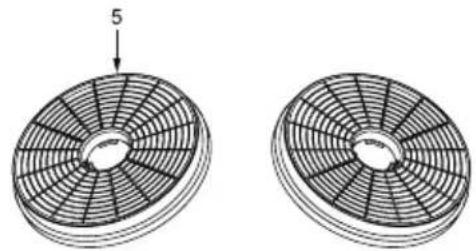
natural_image
Two circular fan-like structures with radial blades, one labeled with number 5 (no text or symbols on the fan itself)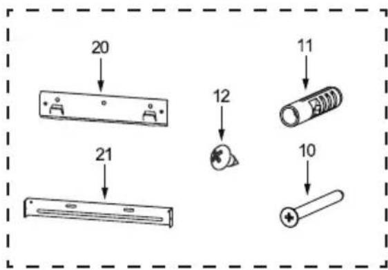
unità: mm


FORATURA A PARETE E FISSAGGIO CON STAFFA
natural_image
Simple line drawing of a blank rectangular frame with no text, numbers, or symbols
natural_image
Simple line drawing of a rectangular object with a horizontal base and a flat top (no text or symbols)natural_image
Technical diagram showing a mechanical assembly with a dashed circular inset view of a component (no text or symbols present)PANNELLO DI CONTROLLO

natural_image
Illustration of a hand holding a tablet with a finger pointing at it, showing a download icon (no text or symbols present)FILTRO A CARBONE ATTIVO (VERSIONE RICIRCOLO)
natural_image
Line drawing of a mechanical component with hands operating it (no text or symbols)
natural_image
Technical line drawing of a mechanical component with a curved top and rectangular base (no text or symbols)natural_image
Line drawing of a hand holding a small object near a surface (no text or symbols)natural_image
Technical line drawing of a cabinet or enclosure assembly with mounting base (no text or symbols)
natural_image
Simple line drawing of a laboratory setup with a conical flask, heating a test tube, and a control panel (no text or symbols)

natural_image
Simple line drawing of a house with a stove and fire, no text or symbols presentnatural_image
Two circular fan-like structures with radial blades, one labeled with number 5 (no text or symbols on the fan itself)
Einheit: mm

natural_image
Simple line drawing of a blank rectangular frame with no text, numbers, or symbols
natural_image
Simple line drawing of a rectangular monitor or screen with no text, numbers, or symbolsRichtig Falsch
natural_image
Technical diagram showing a mechanical assembly with a dashed circular inset view of a component (no text or symbols present)BEDIENFELD
natural_image
Illustration of a hand holding a tablet with a finger pointing at it, showing a download arrow (no text or symbols present)AKTIVKOHLEFILTER (UMLUFTVERSION)
natural_image
Line drawing of a mechanical component with internal parts (no text or symbols)
natural_image
Technical line drawing of a mechanical component with a curved top and rectangular base (no text or symbols)natural_image
Line drawing of a hand gripping a surface with a small object nearby (no text or symbols)natural_image
Technical line drawing of a cabinet mounted on a base plate (no text or symbols)natural_image
Simple line drawing of a laboratory setup with a conical flask, smoke rising, and a control panel (no text or symbols)

natural_image
Simple line drawing of a house with a chimney and fire, no text or symbols presentnatural_image
Two circular fan-like structures with radial blades, one labeled with number 5 (no text or symbols on the fan itself)
ед. измерения: мм


natural_image
Simple line drawing of a blank rectangular panel or monitor (no text or symbols)
natural_image
Simple line drawing of a rectangular object with a horizontal line at the bottom (no text or symbols)natural_image
Technical diagram showing a mechanical assembly with a dashed circular inset view of a component (no text or symbols present)ПАНЕЛЬ УПРАВЛЕНИЯ
natural_image
Illustration of a hand interacting with a tablet device, showing a finger pointing at the screen (no text or symbols present)natural_image
Pure technical line drawing of a mechanical component without any text, numbers, or symbols
natural_image
Technical line drawing of a mechanical component with a curved top and rectangular base (no text or symbols)natural_image
Line drawing of a hand holding a small object near a surface (no text or symbols)MANUEL D'INSTRUCTIONS
MODÈLE LO: HMK 90A3 MS-BS SP BK HMK 90A3 MS SP BK
natural_image
Technical line drawing of a cabinet or enclosure assembly with mounting base (no text or symbols)
natural_image
Simple line drawing of a laboratory setup with a conical flask, a control panel, and a steaming base (no text or symbols)
natural_image
Simple line drawing of a house with a chimney and fire, no text or symbols present
natural_image
Two circular fan-like structures with radial blades, one labeled with number 5 (no text or symbols on the fan itself)
unité : mm


PERÇAGE DU MUR ET FIXATION DU SUPPORT

natural_image
Simple line drawing of a blank rectangular frame with no text, numbers, or symbols
natural_image
Simple line drawing of a rectangular object with a horizontal bar at the bottom (no text or symbols)Correct Incorrect
natural_image
Technical diagram showing a mechanical assembly with a dashed circular inset view of a component (no text or symbols present)PANNEAU DE COMMANDE

natural_image
Illustration of a hand interacting with a tablet device, showing a finger pointing at the screen (no text or symbols present)FILTRE À CHARBON ACTIF (VERSION RECIRCULATION)
natural_image
Line drawing of a mechanical component with no visible text or symbols
natural_image
Technical line drawing of a mechanical component with a curved top and rectangular base (no text or symbols)natural_image
Line drawing of a hand holding a rectangular object with a curved handle (no text or symbols)UPUTSTVO ZA UPUTSTVO
MODELLO: HMK 90A3 MS-BS SP BK
HMK 90A3 MS SP BK
natural_image
Technical line drawing of a cabinet or enclosure assembly with mounting base (no text or symbols)
Uputstvo za upotrebu se odnosi na nekoliko verzija ovog aparata. U skladu sa tim, možda
ćete pronaći opise pojedinačnih funkcija koje se ne primenjuju na vaš određeni aparat.
INSTALACIJA
- Proizvođač neće biti odgovoran za bilo kakvu štetu nastalu neispravnom ili nepravilnom instalacijom.
- Minimalna sigurnosna razdaljina između vrha šporeta i haube ekstraktora je 650 mm (neki modeli se mogu instalirati u nižoj visini, molimo vas da pogledate pasuse o radnim dimenzijama i instalaciji).
- Proverite da li glavni napon odgovara onom naznačenom na ploči za ocenjivanje fiksiranoj za unutrašnjost haube.
- Za aparate klase I proverite da li domaće snabdevanje električnom energijom garantuje adekvatno zemljozemlju.
- Povežite ekstraktor sa izduvnim gripom kroz cev minimalnog prečnika 120mm. Put gripa mora biti kraći.
- Nemojte povezivati haubu ekstraktora sa izduvnim kanalima koji nose zapaljive flume (kotlovi, kamini itd.).
- Ako se ekstraktor koristi zajedno sa neelektrisanim aparatima (npr. aparatima za sagorevanje gasa), u prostoriji mora biti zagarantovan dovoljan stepen aeracije kako bi se sprečio priliv izduvnih gasova. Kuhinja mora imati otvor koji direktno komunicira sa otvorenim vazduhom kako bi se garantovao ulazak čistog vazduha. Kada se hauba šporeta koristi zajedno sa aparatima koji se snabdevaju energijom koja nije električna, negativan pritisak u prostoriji ne sme da pređe 0,04 mbar kako bi se sprečilo da isparenja budu uvučena nazad u prostoriju pored haube šporeta.
- U slučaju oštećenja kabla za napajanje, on mora biti zamenjen proizvođačem ili odeljenjem tehničke službe, kako bi se sprečili bilo kakvi rizici.
- Ako uputstvo za instalaciju za gasnu ploču navede veću udaljenost navedenu iznad, to mora da se uzme u obzir. Propisi koji se odnose na pražnjenje vazduha moraju biti ispunjeni.
KORISTITE
- Hauba ekstraktora je dizajnirana isključivo za domaću upotrebu za eliminisanje kuhinjskih mirisa.
- Nikada ne koristite haubu u druge svrhe osim za koju je dizajnirana.
- Nikada ne ostavljajte visoke gole plamenove ispod haube kada je u funkciji.
- Podesite intenzitet plamena tako da ga usmeri samo na dno pleha, pa ćete se pobrinuti da ne zahvati strane.
- Duboke masne pržioce se moraju neprekidno pratiti tokom upotrebe: prenaglašeno ulje može da bukne u plamenu.
- Ne plamenite ispod dometa haube; rizik od požara.
- Ovaj uređaj ne smiju upotrebljavati djeca mlađa od 8 godina te osobe smanjenih fizičkih, osjetilnih i mentalnih sposobnosti, kao ni osobe s nedostatkom potrebnog znanja i iskustva, bez nadzora ili pomoći osobe odgovorne za njihovu sigurnost, koja će ih uputiti u sigurno rukovanje uređajem i pobrinuti se da razumiju opasnosti povezane s rukovanjem.
- Djeca moraju biti pod nadzorom i ne smiju se igrati uređajem.
- Čišćenje i održavanje ne smiju vršiti djeca bez nadzora.
- "OPREZ: Pristupačni delovi mogu postati vrući kada se koriste sa aparatima za kuvanje".
ODRŽAVANJE
- Isključite ili isključite aparat iz glavne zalihe pre obavljanja bilo kakvih radova na održavanju.
- Očistite i/ili zamenite Filtere nakon navedenog perioda kreča (Opasnost od požara).
- Očistite haubu koristeći vlažnu krpu i neutralni tečni deterdžent.
- Ap pliansa koristi najviše 4 hob elementa.
Simbol koji se ambalaža ukazuje na to da se ovaj proizvod možda ne tretira kao kućni otpad. Umesto toga, biće predata na primenljivo mesto prikupljanja za reciklažu električne i elektronske opreme. Obezbeđivanjem pravilnog odlaganja ovog proizvoda pomoći ćete u sprečavanju potencijalnih negativnih posledica po životnu sredinu i ljudsko zdravlje, koje bi inače mogle biti uzrokovane neprikladnim rukovanjem otpadom ovog proizvoda. Za detaljnije informacije o recikliranju ovog proizvoda obratite se lokalnoj gradskoj kancelariji, usluzi za odlaganje kućnog otpada ili prodavnici u kojoj ste kupili proizvod.
natural_image
Simple line drawing of a laboratory setup with a conical flask, a control panel, and a steaming base (no text or symbols)

natural_image
Simple line drawing of a house with a chimney and fire, no text or symbols present| Ref. | Kol. | Komponente proizvoda |
| 1 | 1 | Hood Body, kompletno sa: Kontrole, Svetlo, Duuer, Filter. |
| 2.1 | 1 | Donji ukrasni dimnjak (opciono) |
| 2.2 | 1 | Gornji ukrasni dimnjak (opciono) |
| 3 | 1 | Flange (opciono) |
| 4 | 1 | Izduvna cev |
| 5 | 2 | Aktivirani filter za ugalj (opciono |
| Ref. Kol. Instalacione komponente | ||
| 10 7 Šrafovi 5 x 50 | ||
| 11 7 Zidni utikači | ||
| 12 6 Šrafovi 4,2 x 9,5 | ||
| 13 2 Montažna zagrada | ||
| 20 | 1 | Zagrada za sređivanje haube (opciono) |
| 21 | 1 | Zagrada za sređivanje dimnjaka (0/1 opciono) |
natural_image
Two circular fan-like structures with radial blades, one labeled with number 5 (no text or symbols on the fan itself)
jedinica:mm

BUŠENJE ZIDOVA I SREĐIVANJE ZAGRADA

natural_image
Simple line drawing of a blank rectangular frame with no text, numbers, or symbols
natural_image
Simple line drawing of a rectangular object with a horizontal base and a flat top (no text or symbols)Ispravan Netočno
- Sa unutrašnje strane tela haube popravite šrafove 10 do Zidnih utikača 11na tačkama (3).
- Uklopi filter u haubu.
- Zatvorite tablu.
VEZE
DUCTED VERSION AIR EXHAUST SYSTEM
Gornji ukrasni dimnjak
- Blago proširite dve strane gornjeg dimnjaka i zakačite ih između zida i zagrade 21 koji je fiksiran na Donjem ukrasnom dimnjaku.
- Iskoj gornjeg dimnjaka na zagradu 21 sa 2 šrafa 12 (4,2 x 9,5) snabdevena haubom.
natural_image
Technical diagram showing a mechanical assembly with a dashed circular inset view of a cabinet and a cylindrical component (no text or symbols present)KONTROLNA TABLA
| Dugme Naziv Funkcija | ||
 | Svetlo Kratka štampa: Uključite/ugasite svetlo. | |
 | Povezivanje Duga štampa: Uključite funkciju WLAN;Duga presa + kratka presa: Isključivanje funkcije WLAN (Kada bljesak) | |
 | Filtriranje čistog podsetnika Uključite funkciju, blic dugmeta da podseti filter za čišćenje kada ventilator radi 150 sati. | |
 | Gest Kratka štampa: uključite/isključite kontrolu pokreta. | |
 | Air refresh Uključite funkciju, ventilator trči 15 minuta na svaka 24 sata pri niskoj brzini. | |
 | Brzina Kratka štampa: Podesite brzinu. | |
 | Prebacite 1. kratka štampa: Pokretanje (03 brzina);2. kratka štampa: Odlaganje 3 min;3. kratka štampa: Režim pripravnosti;4. kratka štampa: OFF odmah. | |
 | Mahni rukom sleva nadesno u pripravnosti po statusu da uključiš tajprodukt. Podrazumevana brzina je poslednja brzina koju je postavio korisnik.Podrazumevana brzina je brzina 03 kod prvog uključivanja. U stanju trčanja, mašući rukom na levu stranu da bi ušao u odloženo stanje na 3 minuta. Mašući rukom na desnu stranu da bi se brzina (01-02-03-0b-01) više puta prebacila. | |
KONTROLNA TABLA
| Dugme Naziv Funkcija | ||
 | Svetlo Kratka štampa: Uključite/ugasite svetlo. | |
 | Povezivanje | Duga štampa: Uključite funkciju WLAN;Duga presa + kratka presa: Isključivanje funkcije WLAN (Kada bljesak) |
 | Gest Kratka štampa: uključite/isključite kontrolu pokreta. | |
 | Boost | Kratka štampa: Startup (0b speed),return to 03 speed after 8 min. please select manually if needs it to continue |
 | Brzina Kratka štampa: Podesite brzinu. | |
 | Prebacite | 1. kratka štampa: Pokretanje (03 brzina);2. kratka štampa: Odlaganje 3 min;3. kratka štampa: Režim pripravnosti;4. kratka štampa: OFF odmah. |
 | Mahni rukom sleva nadesno u pripravnosti po statusu da uključiš tajprodukt. Podrazumevana brzina je poslednja brzina koju je postavio korisnik.Podrazumevana brzina je brzina 03 kod prvog uključivanja. U stanju trčanja, mašući rukom na levu stranu da bi ušao u odloženo stanje na 3 minuta. Mašući rukom na desnu stranu da bi se brzina (01-02-03-0b-01) više puta prebacila. | |
FILTERI ZA MASNU KOŽU
ČIŠĆENJE METALNIH SAMODRŽEĆIH FILTERA ZA MASNU KOŽU
- Filteri moraju da se čiste svaka 2 meseca rada, ili češće za posebno tešku upotrebu, a mogu se oprati u mašini za pranje sudova.
- Pull the comfort panels to open them.
- Uklonite filtere jedan po jedan gu ajući ih prema zadnjoj strani haube i istovremeno povlačeći nadole.
- Svaka vrsta savijanja filtera mor da se izbegne prilikom njihovog pranja. Pre nego što ih ponovo uklopite u haubu uverite se da su potpuno suve. (Boja površine filtera može da se menja tokom vremena, ali to nema uticaja na efikasnost filtera
- Prilikom uklapanja filtera u haub obratite pažnju da su montirani u ispravnom položaju drške okrenute ka spolja.
• Zatvorite panel za udobnost.
natural_image
Illustration of a hand holding a tablet with a finger pointing at it, showing a download icon (no text or symbols present)AKTIVIRAN FILTER ZA UGALJ (VERZIJA RECIRKULACIJE)
Ovi filteri se ne peru i ne mogu se regenerisali i moraju se za eniti približno svaka 4 meseca rada ili češće sa teškom upotrebom.
ZAMENA AKTIVIRANOG FILTERA ZA UGALJ
- Otvorite panele za udobnost koji ih vuku nadole.
- Remove the metal grease filter
- Uklonite zasićeni aktivirani filter uglja
- Uklopite nove filtere
• Zamenite filtere za metalnu mast
• Zatvorite panel za udobnost
ODLAGANJE STARIH ELEKTRIČNIH UREĐAJA

natural_image
Pure technical line drawing of a mechanical component without any text, numbers, or symbols
natural_image
Technical line drawing of a mechanical component with a curved top and rectangular base (no text or symbols)• Isključite konektor svetlosti.
- Zamenite svetlo novim istog tipa, pa se uverite da ste ispravno povezali svetlo svetlosnim kablom.
- Ponovo instalirajte svetlo nazad u telo haube.
natural_image
Line drawing of a hand holding a small object near a surface (no text or symbols)natural_image
Technical line drawing of a cabinet or enclosure assembly with mounting base (no text or symbols)natural_image
Illustration of a laboratory setup with a lamp, control panel, and heating equipment (no text or symbols)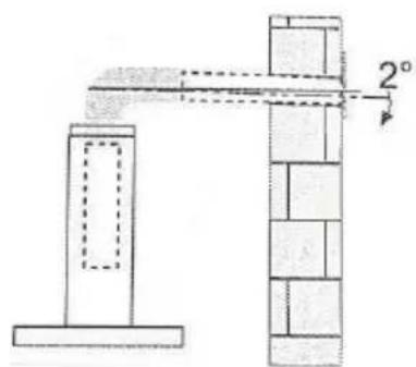
natural_image
Simple line drawing of a house with a chimney and fire, no text or symbols presentnatural_image
Two circular fan-like structures with radial blades, one labeled with number 5 (no text or symbols on the fan itself)
unidad: mm
natural_image
Blank whiteboard with a blank top and bottom margin (no text or symbols)
natural_image
Simple line drawing of a rectangular object with a horizontal base and a flat top (no text or symbols)Correcto Incorrecto
Chimenea Decorativa Superior
natural_image
Technical diagram showing a mechanical assembly with a dashed circular inset view of a component (no text or symbols present)PANEL DE CONTROL
natural_image
Illustration of a hand interacting with a tablet device, showing a finger pointing at the screen (no text or symbols present)natural_image
Line drawing of a mechanical component with internal channels (no text or symbols)