
DSL100HR - Receiver MARSHALL - Free user manual and instructions
Find the device manual for free DSL100HR MARSHALL in PDF.
| Product Type | Guitar Amplifier (Head) |
| Brand | Marshall |
| Model | DSL100HR |
| Power | 100 W (switchable to 50 W) |
| Tubes | 4 x ECC83 and 4 x EL34 |
| Channels | Classic Gain (Clean/Crunch) and Ultra Gain (OD1/OD2) |
| Equalization | Treble, Mid, Bass, Tone Shift, Presence, Resonance |
| Effects | Digital Reverb (Classic and Ultra) |
| Speaker Outputs | 5 x 1/4" jacks (16Ω, 8Ω, 4Ω configurations) |
| Emulated Line Out | 1 x 1/4" jack (Softube® emulation) |
| Effects Loop | Series, Send/Return with switch |
| Footswitch | F/S connector for PEDL-90012 or PEDL-91016 |
| MIDI Input | 1 x 5-pin DIN |
| Auxiliary Audio Input | 1 x 1/4" jack |
| Power Supply | Mains, rated voltage according to country |
| Dimensions (W x H x D) | 740 x 274 x 242 mm |
| Weight | 24.2 kg |
| Safety | Protective fuse, grounding, FCC and ICES-3 compliance |
| Transport | Move only alone, turned off and unplugged |
Frequently Asked Questions - DSL100HR MARSHALL
User questions about DSL100HR MARSHALL
0 question about this device. Answer the ones you know or ask your own.
Ask a new question about this device
Download the instructions for your Receiver in PDF format for free! Find your manual DSL100HR - MARSHALL and take your electronic device back in hand. On this page are published all the documents necessary for the use of your device. DSL100HR by MARSHALL.
USER MANUAL DSL100HR MARSHALL
natural_image
Two black MGVs with 'Marshall' branding displayed on different bases, no visible text or symbols beyond branding.DSL40CR DSL100HR
QUICK START GUIDE
CONGRATULATIONS ON PURCHASING YOUR MARSHALL 1DSL.
Download the full manual at www.marshall.com
QUICK START GUIDE
Warning! Safety instructions 3
Specification 4
Front panel functions 5
Rear panel functions 7
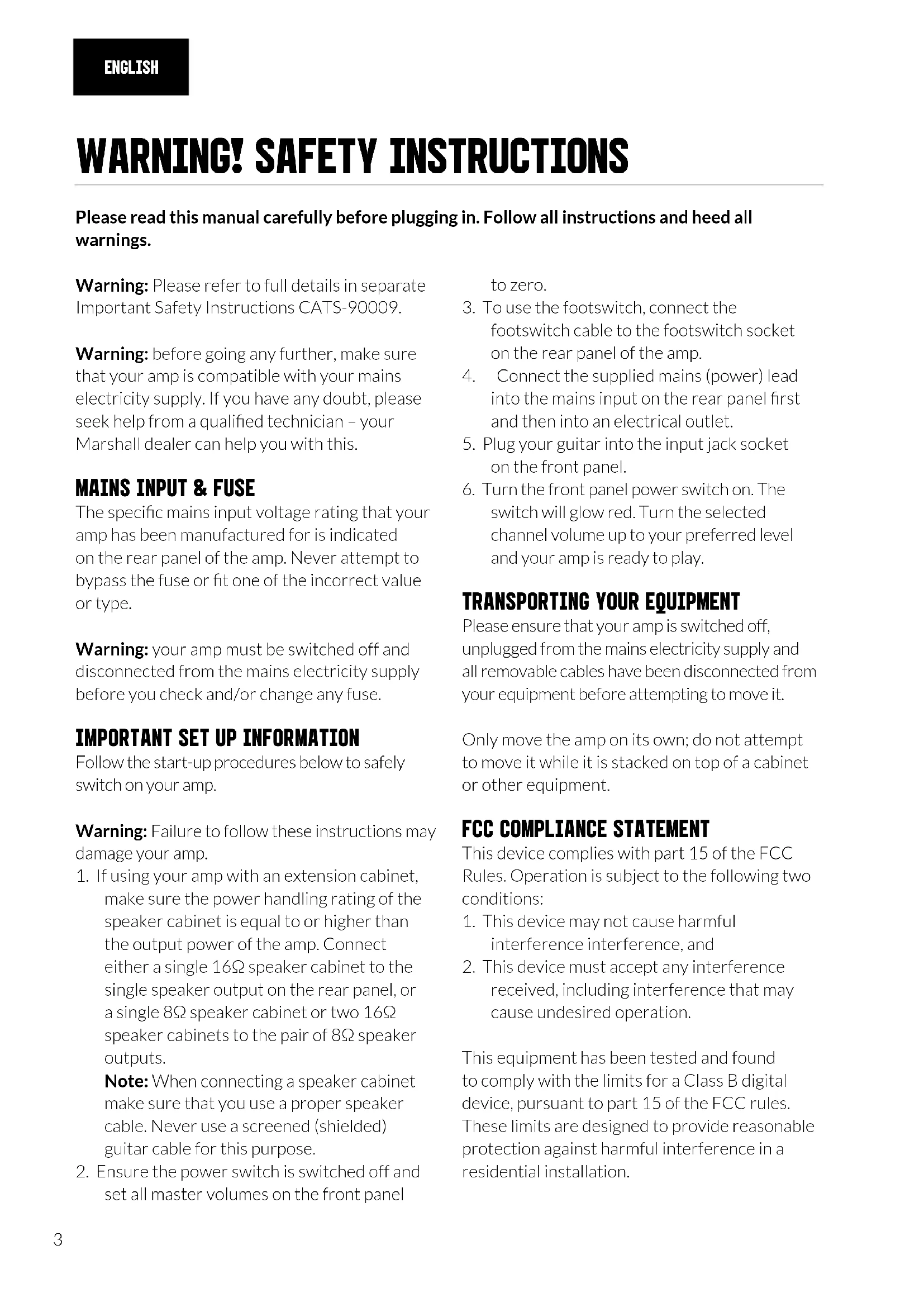
WARNING! SAFETY INSTRUCTIONS
Please read this manual carefully before plugging in. Follow all instructions and heed all warnings.
Warning: Please refer to full details in separate Important Safety Instructions CATS-90009.
Warning: before going any further, make sure that your amp is compatible with your mains electricity supply. If you have any doubt, please seek help from a qualified technician – your Marshall dealer can help you with this.
MAINS INPUT & FUSE
The specific mains input voltage rating that your amp has been manufactured for is indicated on the rear panel of the amp. Never attempt to bypass the fuse or fit one of the incorrect value or type.
Warning: your amp must be switched off and disconnected from the mains electricity supply before you check and/or change any fuse.
IMPORTANT SET UP INFORMATION
Follow the start-up procedures below to safely switch on your amp.
Warning: Failure to follow these instructions may damage your amp.
- If using your amp with an extension cabinet, make sure the power handling rating of the speaker cabinet is equal to or higher than the output power of the amp. Connect either a single 16Ω speaker cabinet to the single speaker output on the rear panel, or a single 8Ω speaker cabinet or two 16Ω speaker cabinets to the pair of 8Ω speaker outputs.
Note: When connecting a speaker cabinet make sure that you use a proper speaker cable. Never use a screened (shielded) guitar cable for this purpose.
- Ensure the power switch is switched off and set all master volumes on the front panel
to zero.
- To use the footswitch, connect the footswitch cable to the footswitch socket on the rear panel of the amp.
- Connect the supplied mains (power) lead into the mains input on the rear panel first and then into an electrical outlet.
- Plug your guitar into the input jack socket on the front panel.
- Turn the front panel power switch on. The switch will glow red. Turn the selected channel volume up to your preferred level and your amp is ready to play.
TRANSPORTING YOUR EQUIPMENT
Please ensure that your amp is switched off, unplugged from the mains electricity supply and all removable cables have been disconnected from your equipment before attempting to move it.
Only move the amp on its own; do not attempt to move it while it is stacked on top of a cabinet or other equipment.
FCC COMPLIANCE STATEMENT
This device complies with part 15 of the FCC Rules. Operation is subject to the following two conditions:
- This device may not cause harmful interference interference, and
- This device must accept any interference received, including interference that may cause undesired operation.
This equipment has been tested and found to comply with the limits for a Class B digital device, pursuant to part 15 of the FCC rules. These limits are designed to provide reasonable protection against harmful interference in a residential installation.
SPECIFICATION
This equipment generates, uses and can radiate frequency energy and, if not installed and used in accordance with the instructions, may cause harmful interference to radio communications.
However, there is no guarantee that interference will not occur in a particular installation. If this equipment does cause harmful interference to radio or television reception, which can be determined by turning the equipment off and on, the user is encouraged to try to correct the interference by one or more of the following measures:
- Reorient or relocate the receiving antenna.
- Increase the separation between the equipment and the receiver.
- Connect the equipment into an outlet on a circuit different from that to which the receiver is connected.
- Consult the dealer or an experienced radio / TV technician for help.
CAUTION: Any changes or modifications not expressly approved by the party responsible for compliance may void the users authority to operate the equipment.
This device complies with CAN ICES-3(B)/NMB-3(B).
From clean to distorted overdrives, the DSL is a versatile all-valve amp packed with features including an effects loop, power reduction switch and digital reverb. Your amp has been specifically designed to sound great at a range of volumes. Perfect for you to use at home, in rehearsals and studios, or on stage.
| MODEL: DSL40CR DSL100HR | ||
| Power | 40W(with power reduction option to 20W) | 100W(with power reduction to 50W) |
| Valves | 4 x ECC83 and 2 x EL34 | 4 x ECC83 and 4 x EL34 |
| Channels | 2 (split) “ultra gain” and “classic gain” | |
| Equalisation | Treble, middle, bass, tone shift switch, presence, resonance | |
| Effects Digital reverb | ||
| Outputs | 5 x 1/4” jack speaker outputs (16Ω load/8Ω load/4Ω load), 1 x 1⁄4” jack emulated line out | |
| Effects loops | Yes, series, send/return, with loop switch | |
| Speakers | 1 x 12”Celestion V-Type speaker (16Ω, 80W) | N/A |
| Unit weight 22.9kg 24.2kg | ||
| Unit width 620mm 740mm | ||
| Unit height 490mm 274mm | ||
| Unit depth 252mm 242mm | ||
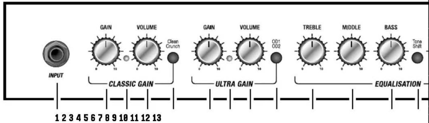
FRONT PANEL FUNCTIONS
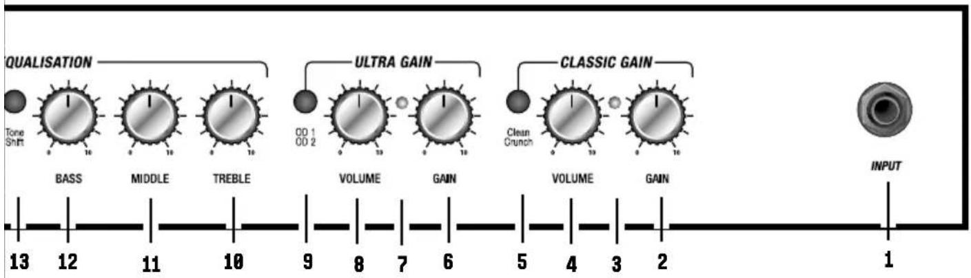
1. INPUT
Connect your guitar here using a 14 " jack instrument cable.
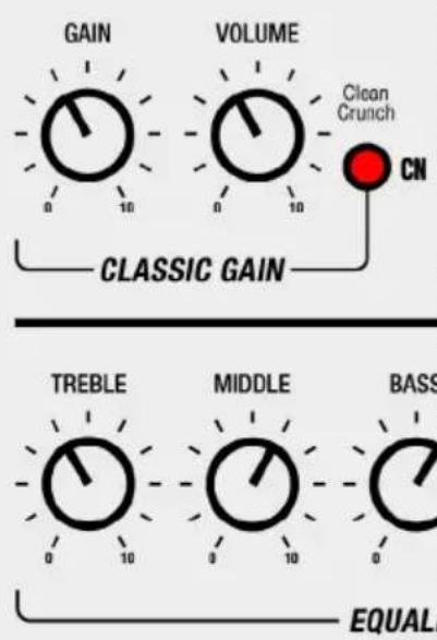
CLASSIC GAIN CHANNEL
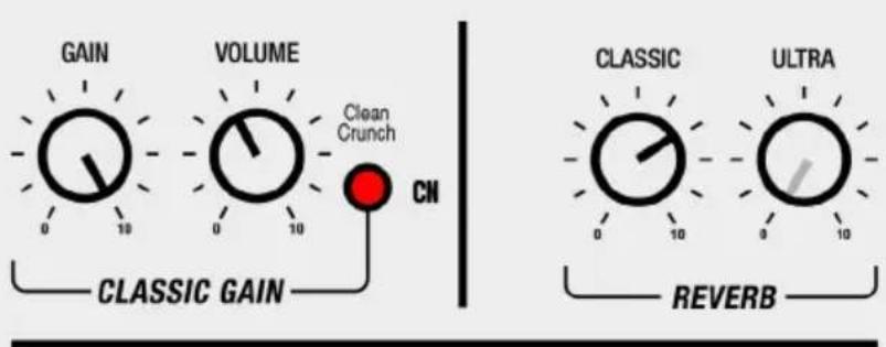
2. GAIN
Controls the gain level for the classic gain channel. Use this control to adjust the amount of input gain/signal sent into the preamp stage. Running a higher gain setting increases the level of distortion in your sound.
3. MODE STATUS LED
This LED lights green to indicate that clean mode is selected and red to indicate crunch mode is selected.
4. VOLUME
Controls the volume level of the classic gain channel.
5. CLEAN/CRUNCH
Press to select clean or crunch mode. The classic gain channel's two modes take your sound from clean to overdriven tones.
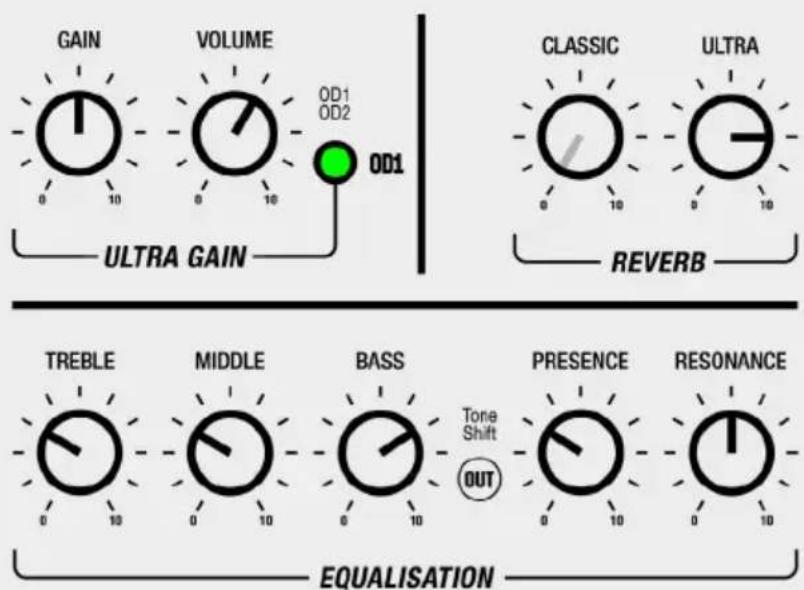
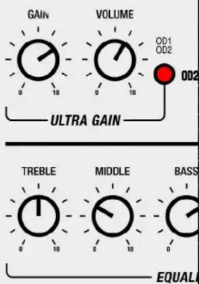
ULTRA GAIN CHANNEL
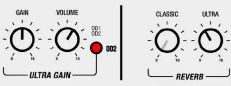
6. GAIN
Controls the gain level for the ultra gain channel. Use this control to adjust the amount of input gain/signal sent into the preamp stage. Running a higher gain setting increases the level of distortion in your sound.
7. MODE STATUS LED
This LED lights green to indicate that OD1 mode is selected and red to indicate OD2 mode is selected.
8. VOLUME
Controls the volume level of the ultra gain channel.
9. OD1/OD2
Press to select OD1 or OD2 mode. The ultra gain channel's two modes take your sound from distorted to heavy gain tones.
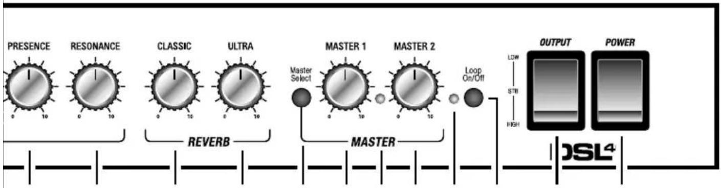
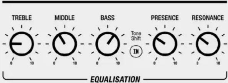
EQUALISATION SECTION
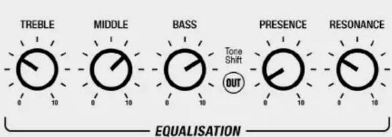
10. TREBLE
Controls the higher frequency content of your sound. Turning clockwise will increase the highs making the sound brighter.
11. MIDDLE
Controls the middle frequencies of your sound. Turning clockwise increases the level of mid frequencies in your sound. Turning anti-clockwise reduces the middle frequencies, 'scooping' the sound – this is accentuated when used in conjunction with Tone Shift.
12. BASS
Controls the amount of lower frequency in your sound. Turning clockwise will increase bottom-end making the sound fuller.
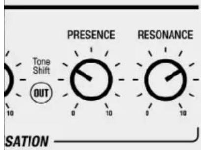
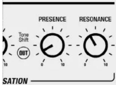
13. TONE SHIFT
Tone shift reconfigures the preamp EQ, giving you a distinctly different sound. When tone shift is engaged, high and low frequencies are accentuated and mid frequencies are cut.
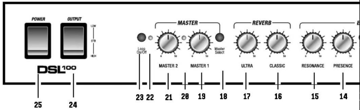
14. PRESENCE
Adjust the power amp EQ to add treble to your sound. Turning clockwise brings out the top end frequencies in your tone.
15. RESONANCE
Adjust the power amp EQ to add body to your sound. Turning clockwise brings out the low end frequencies in your tone.
Note: The EQ controls are linked. Altering the setting of one control can change the way that the other controls behave, so it is worth
experimenting to find your sound.
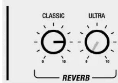
REVERB SECTION
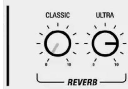
16. CLASSIC REVERB
Controls the reverb level of the classic channel.
17. ULTRA REVERB
Controls the reverb level of the ultra channel.
MASTER VOLUME SECTION
18. MASTER SELECT
Switches between control of Master 1 and Master 2.
19. MASTER 1
Set the overall volume level of Master 1.
20. MASTER STATUS LED
This LED turns green to indicate that Master 1 is selected and red to indicate Master 2 is selected.
21. MASTER 2
Set the overall volume level of Master 2.
22. LOOP STATUS LED
This LED turns green to indicate that the FX loop is on. It is unlit when the FX loop is off.
23. LOOP ON/OFF
This switch turns the FX loop on and off.
24. OUTPUT
Use this switch to reduce power level from 40W down to 20W, or to place the amp into standby mode.
25. POWER
This turns the amp on and off.
REAR PANEL FUNCTIONS
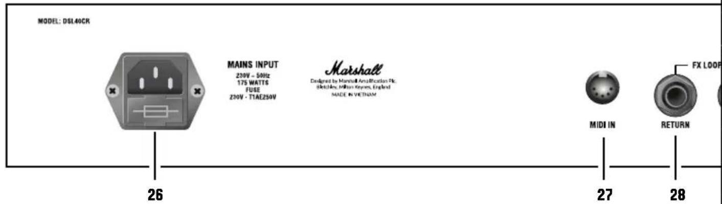
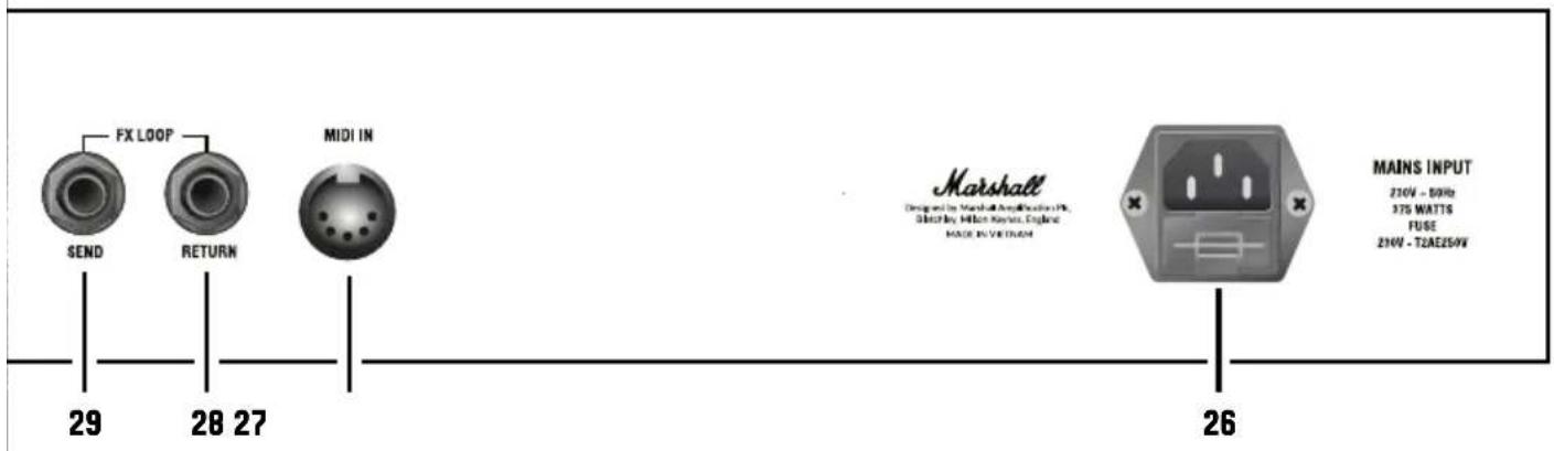
26. MAINS INPUT
The supplied mains power lead is connected here. The mains input voltage rating that your amp has been built for is shown on the rear panel.
Warning: before powering on, ensure the amp is compatible with the mains voltage of the country that the amp is being used in. If you have any doubt, please get advice from a qualified person.
27. MIDI IN
Connect your external MIDI device here.
28. FX LOOP RETURN
Return your signal from external FX equipment here using a 14 " jack instrument cable.
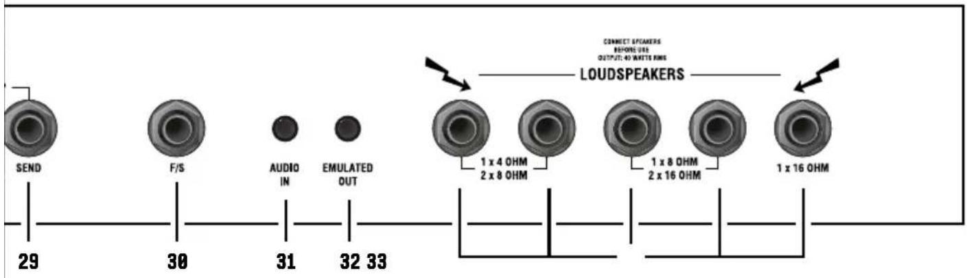
29. FX LOOP SEND
Connect your external FX equipment here using a 14 " jack instrument cable.
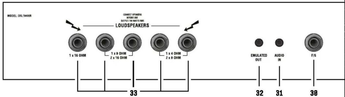
30. F/S
Connect the supplied channel footswitch here (PEDL-90012) or optional footswitch (PEDL-91016).
31. AUDIO IN
Connect an external device here to practice with or jam along to music.
32. EMULATED OUT
Frequency-compensated line level output for headphones. This output features cabinet emulation by Softube®. This means the sound from this output includes simulation of the sound of a speaker and a cab.
33. SPEAKER OUTPUTS
1/4" jack speaker outputs. They are labelled according to the corresponding cabinet setups:
- 1 x 16 Ohm: connect a 16Ω speaker cabinet.
- 1 x 8 Ohm / 2 x 16 Ohm: connect a single 8Ω guitar cabinet or two 16Ω cabinets.
- 1 x 4 Ohm / 2 x 8 Ohm: connect a single 4Ω guitar cabinet or two 8Ω guitar cabinets.
Warning: although the amp has five speaker outputs, never attempt to connect more speakers than rated. The safe combinations are listed above. Any other speaker configuration may stress or damage the amp.
AVERTISSEMENT ! CONSIGNES DE SÉCURITÉ
DÉCLARATION DE CONFORMITÉ
33. USCITE DIFFUSORE
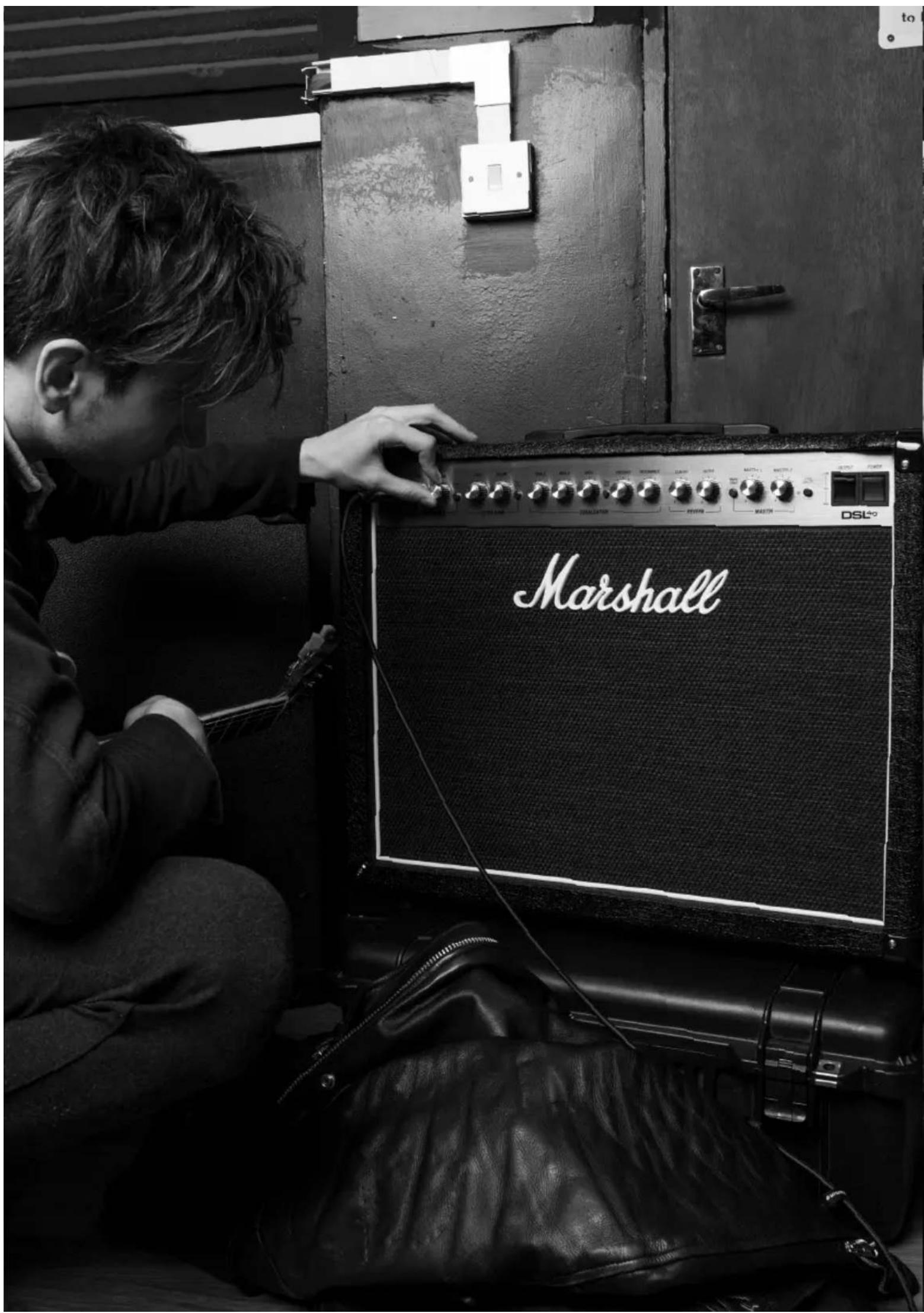
natural_image
Black-and-white photo of audio equipment including a vinyl audio amplifier, microphone, and guitar (no visible text or symbols)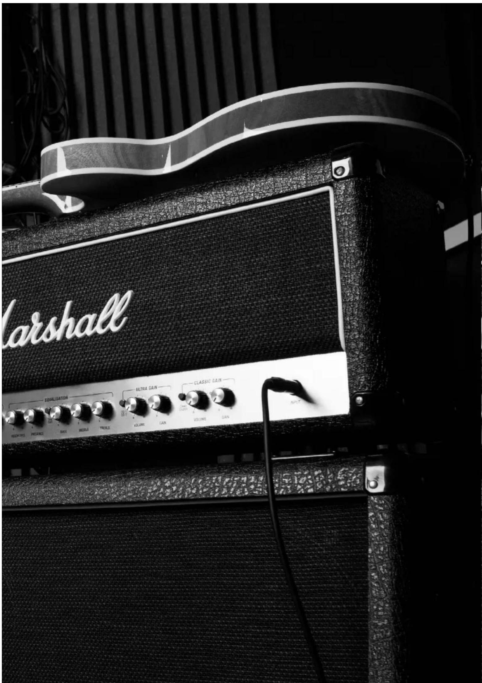
DSL40CR
flowchart
graph LR
    INPUT["INPUT"] --> GAIN1["GAIN 0-10"]
    GAIN1 --> VOLUME1["VOLUME 0-10"]
    VOLUME1 --> CleanCrunch["Clean Crunch"]
    CleanCrunch --> GAIN2["GAIN 0-10"]
    GAIN2 --> VOLUME2["VOLUME 0-10"]
    VOLUME2 --> OD1["OD1 OD2"]
    OD1 --> TREBLE["TREBLE 0-10"]
    TREBLE --> MIDDLE["MIDDLE 0-10"]
    MIDDLE --> BASS["BASS 0-10"]
    BASS --> ToneShift["Tone Shift"]

    GAIN3["GAIN 0-10"] --> VOLUME3["VOLUME 0-10"]
    VOLUME3 --> ULTRA_GAIN["ULTRA GAIN"]
    ULTRA_GAIN --> OD2["OD2"]

    style INPUT fill:#f9f,stroke:#333
    style GAIN fill:#ccf,stroke:#333
    style VOLUME fill:#cfc,stroke:#333
    style END fill:#fff,stroke:#333
DSL100HR
flowchart
graph LR
    A["PRESENCE"] --> B["RESONANCE"]
    B --> C["CLASSIC"]
    C --> D["ULTRA"]
    D --> E["MASTER 1"]
    E --> F["MASTER 2"]
    F --> G["Master Select"]
    G --> H["MASTER"]
    H --> I["Master"]
    I --> J["Loop On/Off"]
    J --> K["OUTPUT"]
    J --> L["POWER"]
    M["DSL⁴"] --> N["High"]
    N --> O["STB"]
    N --> P["LOW"]
14 15 16 17 18 19 20 21 22 23 24 25
flowchart
graph LR
    A["Tone Shift"] --> B["BASS"]
    B --> C["MIDDLE"]
    C --> D["TREBLE"]
    D --> E["ULTRA GAIN"]
    E --> F["OD 1 OD 2"]
    F --> G["VOLUME"]
    G --> H["GAIN"]
    H --> I["CLASSIC GAIN"]
    I --> J["Clean Crunch"]
    J --> K["VOLUME"]
    K --> L["GAIN"]
    L --> M["INPUT"]
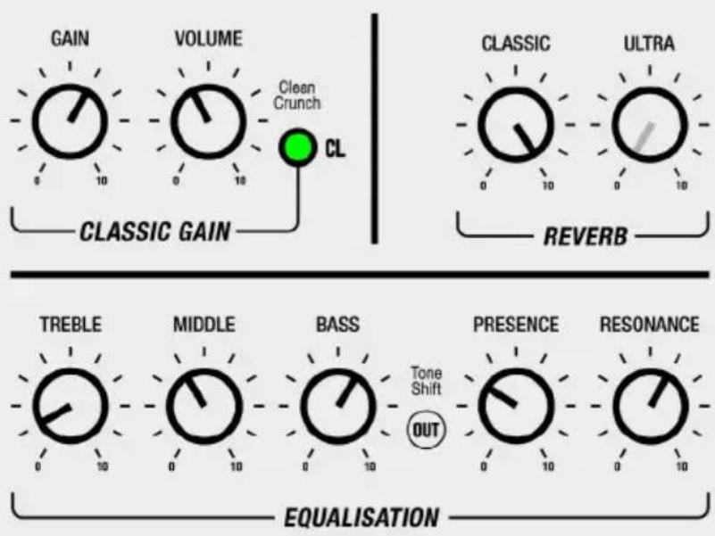
STARTING SETTINGS
With your DSL you should find a sound that suits you. It's the best way to stand out from the crowd and release your alter ego. However, if you're looking for some inspiration here's some settings to get started.
CLASSIC CLEAN CLASSIC
flowchart
graph TD
    A["GAIN"] --> B["VOLUME"]
    B --> C["CL"]
    D["CLASSIC GAIN"] --> E["CL"]
    F["CLASSIC"] --> G["ULTRA"]
    H["REVERB"] --> I["TREBLE"]
    J["MIDDLE"] --> K["BASS"]
    L["PRESENCE"] --> M["RESONANCE"]
    N["EQUALISATION"] --> O["TONE SHIFT OUT"]
MODERN DRIVE MODERN
flowchart
graph TD
    A["GAIN"] --> B["VOLUME"]
    B --> C["ULTRA GAIN"]
    D["CLASSIC"] --> E["ULTRA"]
    F["REVERB"] --> G["TREBLE"]
    H["MIDDLE"] --> I["BASS"]
    J["PRESENCE"] --> K["RESONANCE"]
    L["EQUALISATION"] --> M["OUT"]
    style A fill:#f9f,stroke:#333
    style B fill:#f9f,stroke:#333
    style C fill:#9cf,stroke:#333
    style D fill:#f9f,stroke:#333
    style E fill:#f9f,stroke:#333
    style F fill:#f9f,stroke:#333
    style G fill:#f9f,stroke:#333
    style H fill:#f9f,stroke:#333
    style I fill:#f9f,stroke:#333
    style J fill:#f9f,stroke:#333
    style K fill:#f9f,stroke:#333
    style L fill:#f9f,stroke:#333
    style M fill:#f9f,stroke:#333
CRUNCH
BLUES LEAD
N LEAD
SCOOPED RHYTHM
Whilst the information contained herein is correct at the time of publication, due to its policy of constant improvement and development, Marshall Amplification Plc reserves the right to alter specifications without prior notice.
MARSHALL AMPLIFICATION PLC, DENBIGH ROAD, BLETCHLEY, MILTON KEYNES, MK1 1DQ, ENGLAND.
T: +44 (0) 1908 375411
MARSHALL AMPLIFICATION PLC REGISTERED IN ENGLAND REGISTERED NUMBER: 805676
M3311.415 | CATS-90264-05
MARSHALL.COM
- DSL40CR DSL100HR
- CONGRATULATIONS ON PURCHASING YOUR MARSHALL 1DSL.
- QUICK START GUIDE
- WARNING! SAFETY INSTRUCTIONS
- MAINS INPUT & FUSE
- IMPORTANT SET UP INFORMATION
- TRANSPORTING YOUR EQUIPMENT
- FCC COMPLIANCE STATEMENT
- SPECIFICATION
- FRONT PANEL FUNCTIONS
- INPUT
- CLASSIC GAIN CHANNEL
- GAIN
- MODE STATUS LED
- VOLUME
- CLEAN/CRUNCH
- ULTRA GAIN CHANNEL
- GAIN
- MODE STATUS LED
- VOLUME
- OD1/OD2
- EQUALISATION SECTION
- TREBLE
- MIDDLE
- BASS
- TONE SHIFT
- PRESENCE
- RESONANCE
- REVERB SECTION
- CLASSIC REVERB
- ULTRA REVERB
- MASTER VOLUME SECTION
- MASTER SELECT
- MASTER 1
- MASTER STATUS LED
- MASTER 2
- LOOP STATUS LED
- LOOP ON/OFF
- OUTPUT
- POWER
- REAR PANEL FUNCTIONS
- MAINS INPUT
- MIDI IN
- FX LOOP RETURN
- FX LOOP SEND
- F/S
- AUDIO IN
- EMULATED OUT
- SPEAKER OUTPUTS
- AVERTISSEMENT ! CONSIGNES DE SÉCURITÉ
- DÉCLARATION DE CONFORMITÉ
- USCITE DIFFUSORE
- STARTING SETTINGS
Brand : MARSHALL
Model : DSL100HR
Category : Receiver