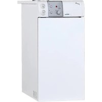
Estelle HE B4 INOX ErP - Boiler SIME - Free user manual and instructions
Find the device manual for free Estelle HE B4 INOX ErP SIME in PDF.
| Product type | Oil condensing boiler, low temperature |
| Brand | SIME |
| Model | Estelle HE B4 INOX ErP |
| Product code (PIN) | 1312CR193R |
| Seasonal heating energy efficiency class | A |
| Seasonal heating energy efficiency | 93 % |
| Useful output (80-60°C) | 33,0 kW |
| Useful output (50-30°C) | 35,5 kW |
| Heat input | 34,8 kW |
| Dimensions (H x W x D) | 1430 x 550 x 285 mm |
| Weight | 220 kg |
| Power supply | 230 V ~ 50 Hz single-phase |
| Fuel | Oil (diesel, light fuel oil) |
| Maximum working pressure (heating) | 4 bar (392 kPa) |
| Maximum working pressure (DHW) | 7 bar (686 kPa) |
| Boiler water capacity | 24,5 l |
| Domestic hot water tank capacity | 110 l |
| DHW production (continuous flow Δt 30°C) | 720 l/h |
| DHW recovery time (25°C to 55°C) | 12 min |
| Heating temperature adjustment range | 45 to 85 °C |
| Domestic hot water temperature adjustment range | 30 to 60 °C |
| Flue gas temperature (80-60°C) | 73 °C |
| Flue gas temperature (50-30°C) | 30 °C |
| Heat exchanger material | Cast iron and stainless steel (condenser) |
| Compatible burner type | Oil, continuous feed, semi-empty nozzle |
| Maintenance | Annual by approved technician; flue gas side cleaning and magnesium anode check |
| Safety | Pressure switch, safety aquastat (95°C), safety valve 3 bar (heating) and 6 bar (DHW), frost protection |
| Recommended accessories | Safety valve, hydrometer, expansion vessel (DHW), by-pass or flowmeter |
| Main spare parts | Magnesium anode, turbulators, tank pump, burner (not supplied) |
Frequently Asked Questions - Estelle HE B4 INOX ErP SIME
User questions about Estelle HE B4 INOX ErP SIME
0 question about this device. Answer the ones you know or ask your own.
Ask a new question about this device
Download the instructions for your Boiler in PDF format for free! Find your manual Estelle HE B4 INOX ErP - SIME and take your electronic device back in hand. On this page are published all the documents necessary for the use of your device. Estelle HE B4 INOX ErP by SIME.
USER MANUAL Estelle HE B4 INOX ErP SIME
natural_image
Exterior view of a modern stainless steel industrial machine with a crescent-shaped vent and control panel (no visible text or symbols)IT
NL
ES
DE
ENG
SL
FR
GR
Gentile Cliente,
text_image
Technical diagram of an internal device with numbered components, likely a control panel or industrial enclosure.LEGENDA
text_image
Technical diagram of a mechanical device with labeled components and parts, including a central circular component and a tool inserted into a housing.natural_image
Technical line drawing of a mechanical assembly with a hand tool, showing internal components and a close-up of the internal structure (no text or symbols present)natural_image
Technical line drawing of a mechanical device with open lid and internal components (no text or symbols)3.3 PULIZIASTAGIONALE
text_image
Technical diagram of a refrigerator internal structure with numbered components and an inset showing hand positioning for cleaning.Fig. 9
text_image
Technical diagram of a device interior with numbered components and labeled parts, including ASIMOS branding.LEYENDA
natural_image
Technical line drawing of a mechanical assembly with a hand operating a tool, alongside a detailed close-up of the internal components (no text or symbols)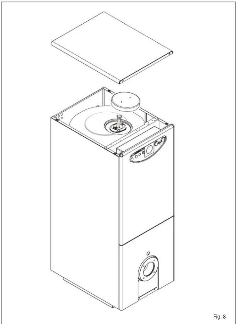
natural_image
Technical line drawing of a multi-tiered industrial machine with open lid and internal components (no text or symbols)text_image
Technical diagram of a washing machine with numbered components and exploded viewFig. 9
1.7 WATER HEAD LOSSES
1.8 MAIN COMPONENTS 33
2 INSTALLATION
2.1 BOILER ROOM.... 34
2.2 BOILER ROOM DIMENSIONS
2.3 CONNECTING UP SYSTEM
2.4 CONNECTING UP FLUE
2.5 CONNECTION OF CONDENSATION WATER TRAP 35
2.6 ELECTRICAL CONNECTION
3 USE AND MAINTENANCE
3.1 COMMISSIONING THE BOILER 36
Our Company declares that ESTELLE HE B4 INOX ErP boilers comply with the essential requirements of the following directives:
- Boiler Efficiency Directive 92/42/EEC
- Ecodesign Directive 2009/125/EC
- Regulation (EU) N. 813/2013 - 811/2013
- Electromagnetic Compatibility Directive 2014/30/UE
- Low Voltage Directive 2014/35/UE
CE
1 BOILER DESCRIPTION
1.1 INTRODUCTION
The new "Estelle HE B4 INOX ErP" series of cast iron boilers condensing, for heating and the production of domestic hot water, they use light oil and have a perfectly balanced combustion with a very high ther-
mal efficiency for economical performance.
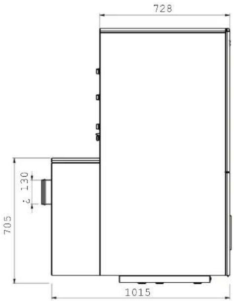
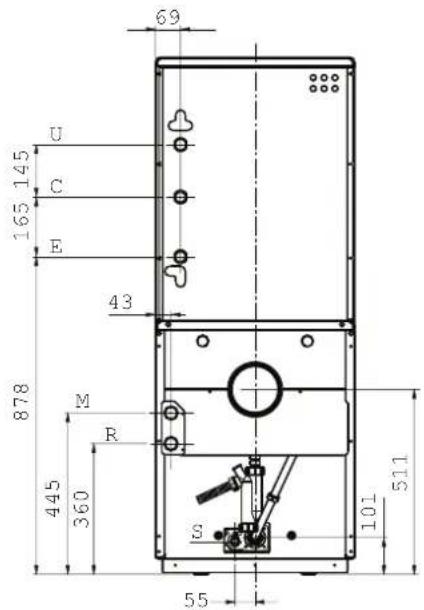
1.2 DIMENSIONAL DETAILS (fig. 1)
text_image
550 1430 285 - -KEY
M C.H. flow G 1" (UNI-ISO 228/1)
R C.H. return G 1" (UNI-ISO 228/1)
U D.H.W. outlet G 3/4" (UNI-ISO 228/1)
text_image
728 705 130 1015E D.C.W. inlet G 3/4" (UNI-ISO 228/1)
C Recirculation G 3/4" (UNI-ISO 228/1)
S Boiler drain
text_image
69 U 145 O 165 E 43 878 M R 445 360 101 511 55Fig. 1
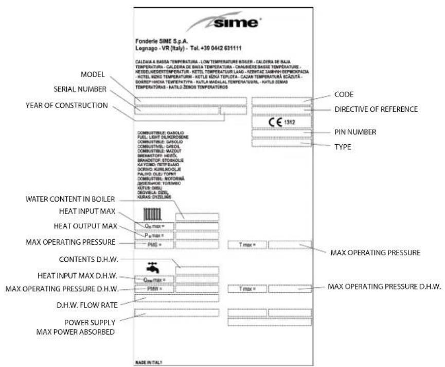
1.2.1 Technical data plate (fig. 1/a)
text_image
sime® Fonderle SIME S.p.A. Legnago - VR (Italy) - Tel. +30 0442 631111 MODEL SERIAL NUMBER YEAR OF CONSTRUCTION CODE DIRECTIVE OF REFERENCE CO PIN NUMBER TYPE CONSUMITIBLE: BASOLD FUEL LIGHT OLIGEROSENS COMBUSTIBLE: BASOLD COMBUSTIBLE: BASOLD COMBUSTIBLE: MAZOUT BRANDSTOP: MEZO, BRANDSTOP: STOOKOLE KAYTENIC TERT PLAUO SORVO KURBOKOLIE PALVO OLE: TONYI COMBUSTIBLE: MOTORBA GREINMODE TUTSINKO KÜTÜR-ÖMSU DEVELA ÖSEL KURAS-DYSELMS WATER CONTENT IN BOILER HEAT INPUT MAX HEAT OUTPUT MAX MAX OPERATING PRESSURE CONTENTS D.H.W. HEAT INPUT MAX D.H.W. MAX OPERATING PRESSURE D.H.W. D.H.W. FLOW RATE POWER SUPPLY MAX POWER ABSORBED MADE IN ITALY CE 1312 MAX OPERATING PRESSURE MAX OPERATING PRESSURE D.H.W.Fig. 1/a
1.3 TECHNICAL FEATURES
| ESTELLE HE B4 INOX ErP | ||
| Output 80-60°C kW 33.0 | ||
| Output 50-30°C kW 35.5 | ||
| Input kW 34.8 | ||
| Seasonal energy efficiency class of the heating system | A | |
| Seasonal energy efficiency of the heating system % | 93 | |
| D.H.W. load profile declared | XL | |
| D.H.W. energy efficiency % | 67 | |
| PIN number 1312CR193R | ||
| Type | B23P - C23P | |
| Sections | n° | 4 |
| Maximum water head bar (kPa) 4 (392) | ||
| Water content | | 24.5 | |
| Smoke loss of head mbar (kPa) | 0.2 (0.020) | |
| Combustion chamber pressure | mbar (kPa) | 0.2 (0.020) |
| Smokes temperature 80-60°C | °C | 73 |
| Smokes temperature 50-30°C | °C | 30 |
| Smokes flow | m3n/h | 37.2 |
| Smokes volume | dm3 | 12 |
| CO2 | % | 12.5 |
| Heating adjustment range | °C | 45÷85 |
| D.H.W. adjustment range | °C | 30÷60 |
| D.H.W. production | ||
| D.H.W. tank capacity | l | 110 |
| D.H.W. flow rate EN 625 | l/min | 21 |
| D.H.W. flow rate Δt 30°C l/h | 720 | |
| Recovery time from 25°C to 55°C | min | 12 |
| D.H.W. tank max. water head | bar (kPa) 7 (686) | |
| Weight | kg | 220 |
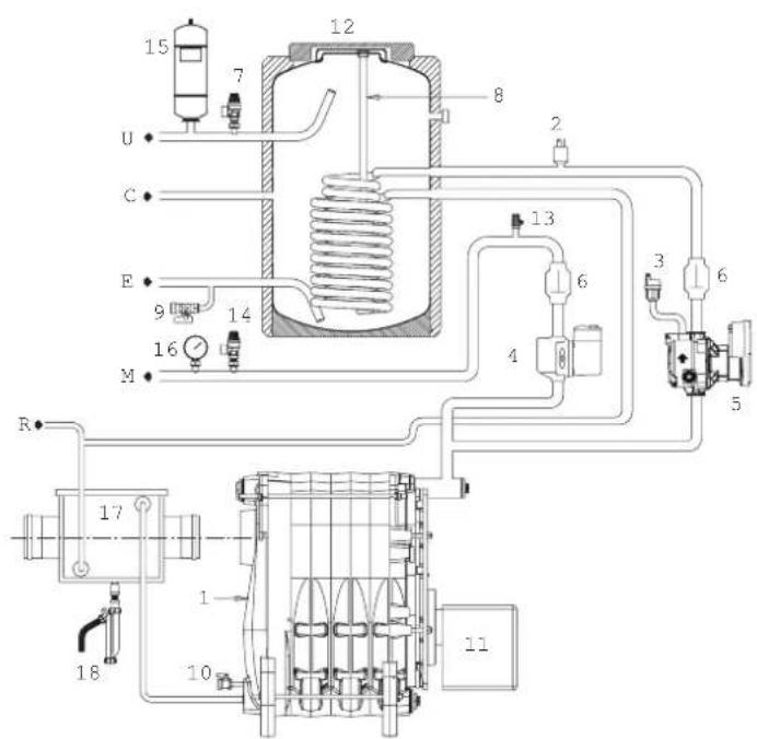
1.4 FUNCTIONAL DIAGRAM
text_image
15 7 12 8 2 U C E 9 14 13 6 4 3 6 5 M R 17 1 10 11 18KEY
1 Cast iron boiler
2 Water switch
3 Automatic air-vent
4 C.H. pump (not supplied)
5 D.H.W. pump
6 Non-return valve
7 D.H.W. safety valve 6 bar/588 kPa (not supplied)
8 Magnesium anode
9 D.H.W. drain cock
10 Boiler drain cock
11 Burner (not supplied)
12 110 litre tank
13 Air vent valve
16 Hydrometer (not supplied)
17 Stainless steel condenser
18 Condensate drain tap
M C.H. flow
R C.H. return
U D.H.W. outlet
E D.C.W. inlet
C Recirculation
14 C.H.safety valve 3 bar/294 kPa (not supplied)
15 D.H.W. tank expansion vessel (not supplied)
Fig. 2
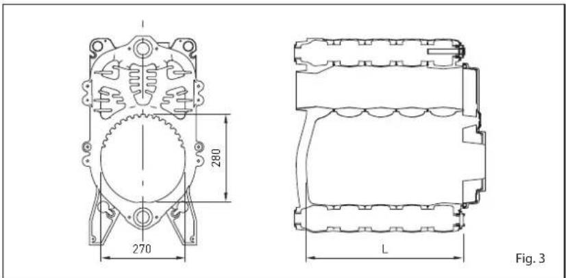
1.5 COMBUSTION CHAMBER (fig. 3)
The combustion chamber is of the straight flow type and complies with standard EN 303-3 appendix E.
The dimensions are shown in fig. 3.
| L | Volumen | ||
| mm | dm | ||
| HE B4 INOX ErP | 405 | 24,0 | |
1.6 COMPATIBLE BURNERS (EN267)
In general, the oil burner that is compatible with the boiler should use spray of the semi solid type.
Section 1.6.1 shows the matching table of the burners together with the boilers have been tested with.
ATTENTION:
Water heater with Nominal Power Pn >70kW: It is possible to use burners that are not on the list but have the same characteristics, as long as they are conforming to the standard/s, reference techniques and suitable field of work.
Water heaters with Nominal Power Pn <70kW: It is possible to use burners that are not on the list but have the same characteristics, as long as they are conforming to the standard/s, reference techniques.
When choosing the burner, pay attention to the max electrical power absorbed by the burner at 30% of the load and in stand-by that should be the same or less that those indicated in ANNEX AA.1.
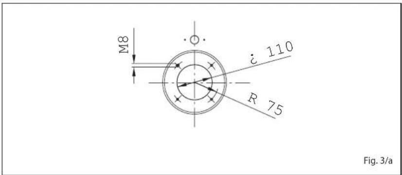
1.6.2 Burners assembly (fig. 3/a)
The boiler door details is shown in figure 3/a for burner mounting.
The burners must be regulated such that the CO_2 value is that indicated in point 1.3, with a tolerance of ±5% .
text_image
280 270 L Fig. 31.6.1 Permanent feeding burner
| Code | Model | Nozzleø | Atomisingangle | Pumppressure bar | ClassNOx | Adsorbed powerconsumption W | |
| HE B4 INOX ErP | 8118503 | SIME FUEL35 EV | 0,65 | 60°H | 12 | 3 | 168 |
text_image
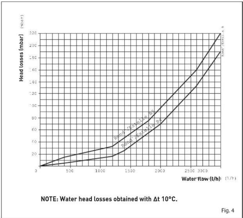
M8 i 110 R 75 Fig. 3/a1.7 WATER HEAD LOSSES (fig. 4)
line
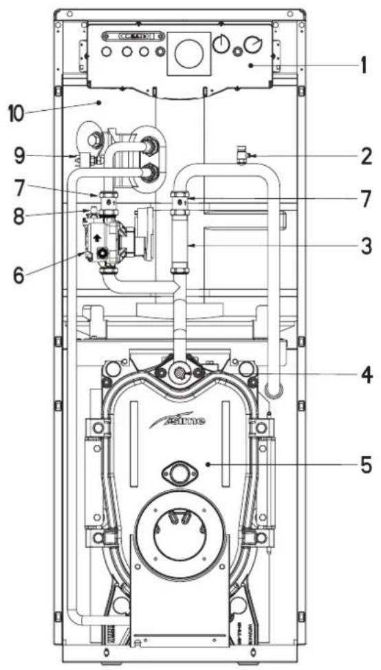
| Water-flow (t/h) (1/h) | Head losses (mbar) for R=0.5 | Head losses (mbar) for R=1.5 | Head losses (mbar) for R=2.5 | | ---------------------- | ---------------------------- | ---------------------------- | ---------------------------- | | 0 | 0 | 0 | 0 | | 500 | ~15 | ~10 | ~5 | | 1000 | ~30 | ~20 | ~10 | | 1500 | ~50 | ~40 | ~25 | | 2000 | ~75 | ~60 | ~45 | | 2500 | ~120 | ~90 | ~80 | | 3000 | ~180 | ~140 | ~120 | | 3500 | ~220 | ~180 | ~160 |1.8 MAIN COMPONENTS (fig. 4/a)
text_image
Technical diagram of an electronic device with numbered components for identificationKEY
1 Control panel
2 Breather valve
3 Connection union 1"
4 Bulb housing sheath
5 Cast iron boiler
6 D.H.W. pump
7 Control valve
8 Air relief valve
9 Water switch
10 110 litre tank
Fig. 4/a
2 INSTALLATION
2.1 BOILER ROOM
The boiler room should feature all the characteristics required by standards governing liquid fuel heating systems.
2.2 BOILER ROOM DIMENSIONS
Position the boiler body on the foundation bed, which should be at least 10 cm high. The body should rest on a surface allowing shifting, possibly by means of sheet metal. Leave a clearance between the boiler and the wall of at least 0.60 m, and between the top of the casing and the ceiling of 1 m (0.50 m in the case of boilers with incorporated D.H.W. tank). The ceiling height of the boiler room should be less than 2.5 m.
2.3 CONNECTING UP SYSTEM
When connecting up the water supply to the boiler, make sure that the specifications given in fig. 1 are observed. All connecting unions should be easy to disconnect by means of tightening rings. A closed expansion tank system must be used.
ATTENTION: The installation of a by-pass or a flow switch (not supplied) is mandatory in the case of installations in systems with thermostatic valves or motorized two-way valves.
The minimum flow rate of the system, which must be guaranteed, must not be lower than that shown below.
Minimum system flow rate 850 (l/h) with T = 35^
2.3.1 Accessories (fig. 2)
To ensure boiler efficiency, and a pressure relief valve set to 3 bar/294 kPa (14) and a hydrometer to check the system pressure (16).
Install a pressure relief valve calibrated to 6 bar/588 kPa (7) on the boiler water outlet pipe to prevent the risk of bursting due to excess pressure build up. If the boiler safety valve cuts in frequently, install a 5-litre expansion vessel (15) with maximum operating pressure of 8 bar/784 kPa on the hot water circuit. The tank should be fitted with a natural rubber food-grade diaphragm. The central heating circuit pump (4) can be installed at the rear of the boiler in place of the connection union 1" pos. 3 fig. 4/a.
2.3.2 Filling the water system
Before connecting the boiler, thoroughly flush the system to eliminate scale which could damage the appliance.
Filling must be done slowly so as to allow any air bubbles to be bled off through the air valves.
In closed-circuit heating systems, the cold water filling pressure and the pre-charging pressure of the expansion vessel should be no less than or equal to the height of the water head of the installation (e.g. for water head of 5 meters, the vessel pre-charging pressure and installation filling pressure should be at least 0.5 bar).
During the preparation of hot water, the circulating pump installed on the boiler circuit remains in operation until the boiler thermostat probe detects the pre-selected value.
Once the boiler thermostat has reach the set point, and the selector has been set to winter operation with the room thermostat on demand, the central heating circuit pump (not supplied) can be actuated.
All residual air in the boiler coils must be bled at the first start-up to ensure proper operation.
To facilitate this operation, position the slot of the release screw on the check valve horizontally (6 fig. 2). Once the air has been bled, return the screw to its original position.
Hot water for sanitary use is prepared by the boiler in AISI 316L stainless steel, which is fitted with a special spiral-shaped stainless steel heat exchanger, a magnesium anode to protect the boiler and an inspection flange to simplify checking and cleaning.
2.3.4 Characteristics of feedwater
To prevent lime scale and damage to the tap water exchanger, the water supplied should have a hardness of no more than 20^ F.
In all cases the water used should be tested and adequate treatment devices should be installed.
To prevent lime scale or deposits on the primary exchanger, the water used to supply the heating circuit should must be treated in accordance with UNI-CTI 8065 standards. The water used for the central heating system should be treated in the following cases:
- For extensive systems (with high contents of water).
- Frequent addition of water into the system.
- Should it be necessary to empty the system either partially or totally.
2.4 CONNECTING UP FLUE
The flue is of fundamental importance for the proper operation of the boiler; if not installed in compliance with the standards, starting the boiler will be difficult and there will be a consequent formation of soot, condensation and encrustation.
A flue therefore must satisfy the following requirements:
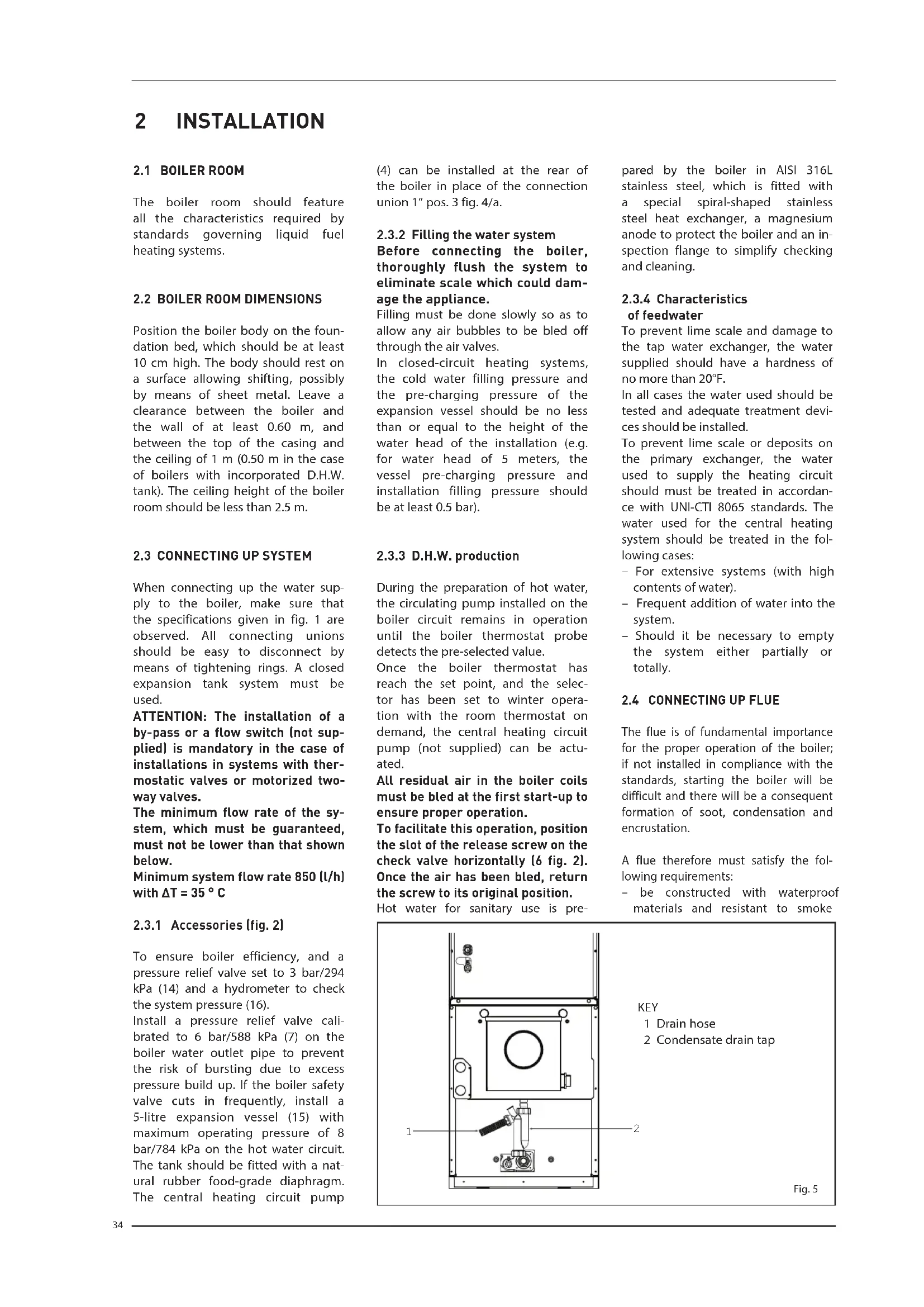
- be constructed with waterproof materials and resistant to smoke
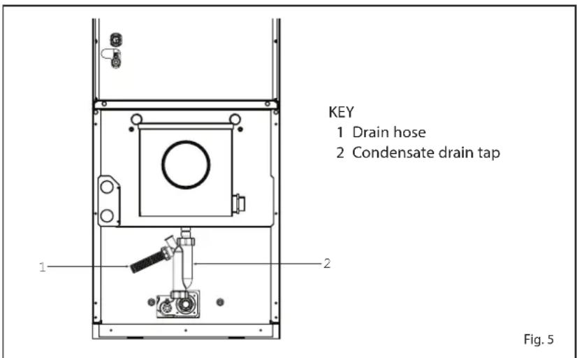
text_image
KEY 1 Drain hose 2 Condensate drain tap 1 2 Fig. 5temperature and condensate;
- be of adequate mechanical resilience and of low heat conductivity;
- be perfectly sealed to prevent cooling of the flue itself;
- be as vertical as possible; the terminal section of the flue must be fitted with a static exhaust device that ensures constant and efficient extraction of products generated by combustion;
- have a diameter that is not inferior to that of the boiler union;
- to be properly sized to meet the flue gas draught/exhaust requirements necessary for regular operation of the product (EN13384-1);
- a specific condensate outlet system must be installed at the bottom of the flue;
- rigid pipes must be used for the connection to the flue, resistant to
high temperatures, condensation, mechanical stress, sealed and insulated. Use material suited to the purpose, such as stainless steel.
2.5 CONNECTION OF CONDENSATION
WATER TRAP (fig. 5)
The drip board and its water trap must be connected to a civil drain through a pipe ( 25) with a slope of at least 5 mm per metre to ensure drainage of condensation water.
The plastic pipes normally used for civil drains are the only type of pipe which is appropriate for conveying condensation to the building's sewer pipes.
2.6 ELECTRICAL CONNECTION (fig. 5/a)
The boiler is fitted with an electricity cable, and requires a single-phase power supply of 230V - 50Hz through the main switch protected by fuses. The room thermostat (required for enhanced room temperature control) should be installed as shown in fig. 5/a. Connect the burner and system circulation pump power cables supplied.
NOTE: Device must be connected to an efficient earthing system.
SI ME de cli nes all responsibility for injury caused to persons due to failure to earth the boiler.
Always turn off the power supply before doing any work on the electrical panel.

text_image
230V-50Hz N L 1 2 3 4 5 6 7 8 9 10 11 12 13 14 15 16 17 18 19 20 21 22 23 E/I TB SA L N 24 25 26 27 28 29 30 31 32 33 SPA IG NERO-BLACK MARR-BROWN ROSSO-RED C NC PA OP PB TL TM c 1 2 13 14 5 9 6 2 10 R2 R2 11 7 4 8 12 11 8 10 9 11 8 TC 11 12 21 24 TA PI TS GRIGIO-GREY BLU-BLUE MA BR DR B4 S3 T2 T1 N B1 L1KEY
TS Safety stat
El Summer/Winter switch
TA Room stat
TB Tank stat
TC Boiler stat
TL Limit stat
IG Main switch
PB D.H.W. pump
PI C.H. pump
B1 Permanent Feeding Burner SIME (optional)
B2 Direct Feeding Burner (not supplied)
R/R2 Relay
SA Power on light
SPA Water pressure
gauge triggered light
PA Water switch
OP Timer programmer (optional)
TM Minimum stat
NOTE: When connecting the room stat (TA) remove the bridge between terminals 20-21.
When connecting the Timer Programmer (OP) remove the bridge between terminals 30-31.
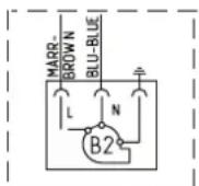
Fig. 5/a
3 USE AND MAINTENANCE
WARNINGS
- In case of failure or malfunction of the equipment, contact authorised technical staff.
- For safety reasons, the User cannot access the internal parts of the appliance. All operations involving the removal of protections or otherwise the access to dangerous parts of the appliance must be performed by qualified personnel.
- The appliance can be used by children under 8 years and by persons with reduced physical, sensory or mental capabilities, or lack of experience or knowledge, provided they are under supervision or after they have been given instructions concerning the safe handling of the appliance and the understanding of the dangers inherent to it. Never let children play with the appliance. Children without supervision must not carry out cleaning and maintenance meant to be carried out by the user.
3.1 COMMISSIONING THE BOILER
When commissioning the boiler always make sure that:
- the system has been filled with water and adequately vented;
- the flow and return valves are fully open;
- the flue and chimney are free from obstructions;
- the electrical connections to the mains and the earthing are correct;
- no flammable liquids or materials are near the boiler;
- check that the circulating pump is not locked.
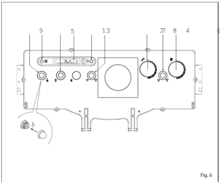
3.2.1 Lighting the boiler (fig. 6)
To light the boiler proceed as follows:
- switch on the main switch (1); the green light turns on to indicate that the appliance is powered (3). The burner will start;
- set the stat knob (7) to the desired D.H.W. temperature.
The boiler pump will continue operating until the preset temperature has been reached.
While the water is being heated, the boiler will continue automatic operation to maintain the heat-
ing temperature shown on the thermometer (5) around 80°C by means of the limit stat (6);
- once the water has been heated with the selector (2) set to the summer function position, the burner and the circulating pump will cease operation; when the selector (2) is set to the winter position, the system pump controlled by the room stat will start up.
In this case, operation of the burn-er will be controlled by the boiler
stat (8) at the preset temperature;
- for best results, set the boiler stat knob (8) to a temperature no lower than 60^ to prevent the formation of condensate.
The set temperature value can be checked on the thermometer (5).
3.2.2 Safety stat (fig. 6)
The manually reset safety stat (4) trips to switch-off the burners immediately when the boiler tem-
text_image
9 5 13 27 8 4 6 Fig. 6perature exceeds 95°C.
To restart the boiler, unscrew the black cover and press the button underneath.
If the problem occurs frequently, call an authorised technical assistance centre for the necessary checks to be carried out.
3.2.3 System filling (fig. 6)
If the orange LED (9) switches on due to the enabling of the water pressure switch and stops the boiler, it is possible to restart it by resetting the plant pressure to 1-1.2 bar (98-117.6 kPa). The system pressure is checked through the hydrometer mounted on the heating delivery tube (16 fig. 2).
3.2.4 Turning OFF boiler (fig. 6)
To turn off the boiler, cut off the voltage by pressing the mains switch (1). Close both the gas-feed pipe tap and the water tap if the boiler remains inoperative for a long period.
3.3 REGULAR CLEANING
Maintenance of the boiler should be carried out annually by an authorised service engineer.
Disconnect the boiler from the electrical supply before servicing or maintenance is carried out.
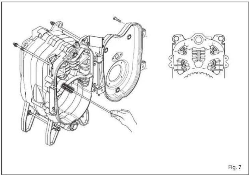
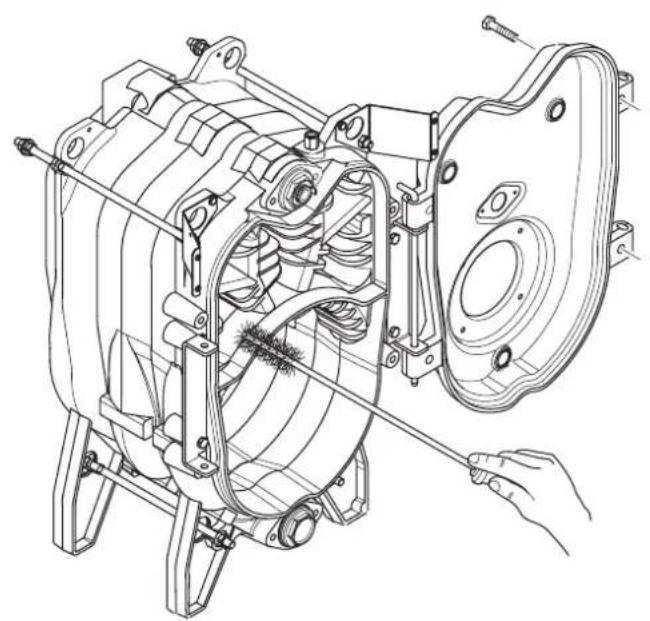
3.3.1 Smoke side boiler (fig. 7)
To carry out cleaning of the smoke passages remove the screws that fix the door to the body of the boiler and with the special cleaning brush clean the internal surfaces and the smoke evacuation tube well, removing any deposits. Once the maintenance is compiled, the baffles have to be fitted onto the original positions.
3.3.2 Tank unit protection anode (fig. 8)
Check the magnesium anode periodically; replace when exhausted. Failure to renew exhausted anodes will render
natural_image
Technical line drawing of a mechanical assembly with a close-up inset showing internal components (no text or symbols)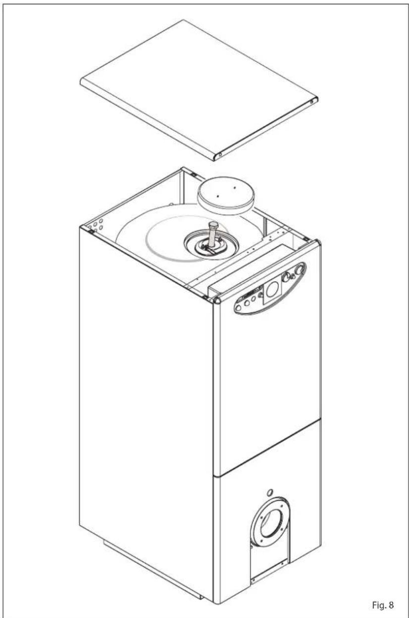
natural_image
Technical line drawing of a multi-tiered industrial machine with open lid and internal components (no text or symbols)the guarantee null and void.
To access the anode, remove the inspection flange that enables the boiler to be checked and cleaned.
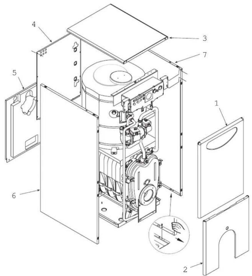
3.3.3 Dismantling the skirt (fig. 9)
The shell can be completely disassembled for an easy maintenance of the boiler by following the numeric steps shown in fig. 9.
3.3.4 Fault finding
Herefater we outline a number of potential problems that may occur on the appliance and the relevant list of actions required.
A working fault, in most cases, provocates the "lock out" signal onto the control panel of the control box. When this light turns on, the burner can operate again only after the reset button has been pressed; if this has been done and a regular ignition occurs, it means the failure can be defined momentary and not dangerous. On the contrary, if the "lock out" stays, the cause of the fault, as well as the relevant action must be made according to the following chart:
The burner does not ignite
- Check the electric connections.
- Check the regular fuel flow, the cleanness of the filters, of the nozzle and air vent from the tube.
- Check the regular spark ignition and the proper function of the burner.
The burner ignites regularly but the flame goes out immediately
- Check the flame detection, the air calibration and the function of the appliance.
Difficulty in regulating the burner and/or lack of yield
- Check: the regular flow of fuel, the
cleanness of the boiler, the non obstruction of the smoke duct, the real input supplied by the burner and its cleanness (dust).
The boiler gets dirty easily
- Check the burner regulator (smoke analysis), the fuel quantity, the flue obstruction and the cleanness of the air duct of the burner (dust).
The boiler does not heat up
- Control the cleanness of the shell, the matching, the adjustment, the burner performances, the pre-adjusted temperature, the correct function and position of the regulation stat.
- Make sure that the boiler is sufficiently powerful for the appliance.
Smell of unburnt products
- Control the cleanness of the boiler shell and the flue, the airtightness of the boiler and of the flue ducts (door, combustion chamber,
text_image
Technical diagram of an open refrigerator internal structure with numbered components and a magnified inset showing internal components.Fig. 9
smoke ducts, flue, washers).
- Control the quality of the fuel.
Frequent intervention of the boiler shutoff valve
- Control the presence of air in the system, the function of the circulation pumps.
- Check the load pressure of the appliance, the efficiency of the expansion tanks and the valve calibration.
3.4 ANTIFREEZE PROTECTION
In freezing weather, make sure that the heating system continues to function and that the rooms are kept warm enough, including the room in which the boiler is installed; if this cannot be done, both the boiler and the heating system must be completely emptied.
Completely emptying the system also means emptying the hot water tank and the hot water heating coil.
3.5 USER WARNINGS
It is mandatory that the dedicated power cable is replaced only with a spare cable ordered and connected by professionally qualified personnel.
ATTENTION: Before performing any work on the boiler, make sure that the same and its components have cooled in order to prevent the risk of burns due to high temperatures.
3.6 DISPOSAL OF THE EQUIPMENT (2012/19/UE)
Once it reaches the end of its operating life, the equipment MUST BE RECYCLED in line with current legislation. IT MUST NOT be disposed
of together with urban waste.
It can be handed over to recycling centres, if there are any, or to retailers that offer this service.
Recycling prevents potential damage to the environment and health. It allows to recover a number of recyclable materials, with considerable savings in terms of money and energy.
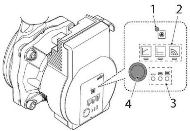
3.7 D.H.W. PUMP (fig. 10)
Press the button (4) briefly (about 1 second) to select the pump operating mode. The relative LEDs will indicate each time the adjustment mode (2) and the characteristic curves set (3).
Point 3.7.4 reports the possible combinations and their meaning.
When the LED (1) signals a fault, the pump stops and attempts to run re-start cycles. If the fault is solved, the pump restarts automatically.
3.7.1 Venting the pump
The pump venting function is activated by pressing the button (4) for a long time (3 seconds) and vents automatically.
3.7.2 Factory settings
The factory setting is activated by pressing and holding the button (4) and disabling the pump. When the pump is restarted, it will work with factory settings (delivery state).
3.7.3 Manual restart
When a lockout is detected, the pump tries to start automatically. If the pump does not restart, restart manually by pressing the button (4) for a long time (5 seconds), then release it. The restart function is activated for a maximum of 10 minutes. After the restart, the LED indication shows the previously set values.
If the fault persists, replace the pump.
text_image
Technical diagram of a mechanical device with labeled components including control panel, display screen, and buttonsFig. 10
3.7.4 Setting the pump operating mode

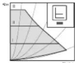
LED display Control mode Pump curve
| 1 Constant speed | II | |
| 2 Constant speed | I | |
| 3 Variable differential | pressure p-v | III |
| 4 Variable differential | pressure p-v | II |
| 5 Variable differential | pressure p-v | I |
| 6 Constant differential | pressure p-c | III |
| 7 Constant differential | pressure p-c | II |
| 8 Constant differential | pressure p-c | I |
| 9 Constant speed | III |
Variable differential pressure p - v (I, II, III)
Recommended for two-pipe heating systems with radiators to reduce the flow noise at thermostatic valves.
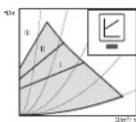
The pump reduces the delivery head to half in the case of decreasing volume flow in the pipe network. Electrical energy saving by adjusting the delivery head to the volume flow requirement and lower flow rates. There are three pre-defined pump curves (I, II, III) to choose from.
Constant differential pressure p - c (I, II, III)
Recommended for underfloorheating for large-sized pipes or all applications without a variable pipe network curve (e.g. storage charge pumps), as well as single-pipe heating systems with radiators.
The control keeps the set delivery head constant irrespective of the pumped volume flow. There are three pre-defined pump curves (I, II, III) to choose from.
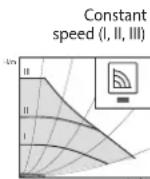
Recommended for systems with fixed system resistance requiring a constant volume flow.
The pump runs in three prescribed fixed speed stages (I, II, III).

Factory setting: Constant speed, pump curve III
- Pressing the button for the 9th time returns to the basic setting (constant speed / characteristic curve III).
3.7.5 Possible pump faults, causes and possible solutions
| Colour of LED | Possible fault Cause Possible solution | ||
| Flashing red-green | Turbine operation | The hydraulic system of the pump is powered, but the pump has no mains voltage | - Check the mains voltage |
| Idle operation Air in the pump | - Check that there are no leaks in the system | ||
| Overload | The motor runs with difficulty. The number of revolutions is lower compared to normal operation | - Check the mains voltage- Check the system flow rate/pressure- Check the characteristics of the water in the system; remove debris from the system | |
| Flashing red | Under/overvoltage | Supply voltage too low/high | - Check the mains voltage |
| Excessive temperature | Excessive temperature inside the pump | - Check the water temperature level in relation to that of the ambient temperature- Check the mains voltage- Check the environmental operating conditions | |
| Short circuit | Motor current too high | - Check the mains voltage | |
| Steady red | “Permanent lockout” stop | Rotor blocked | - Restart manually |
| - REPLACE THE PUMP | |||
| Circuit board and/or motor failure | - REPLACE THE PUMP | ||
| LED Off | Stopped | Electrical power failure | - Check the connection to the power supply |
| Faulty LED | - Check to see if the pump can work | ||
| Faulty circuit board | - REPLACE THE PUMP | ||
TABLE DES MATIERES
1 DESCRIPTION DE LA CHAUDIERE
1.1 INTRODUCTION 42
1.2 DIMENSIONS D'ENCOMBREMENT
text_image
Technical diagram of an internal device with numbered components, likely a control panel or industrial enclosure.LEGENDE
text_image
Technical diagram of a mechanical device with labeled parts 1 and 2, showing internal components and assembly.LEGENDE
1 Tuyau de vidange
2 Siphon
Fig. 5
natural_image
Technical line drawing of an electric motor assembly with a close-up inset showing internal gear mechanisms (no text or symbols)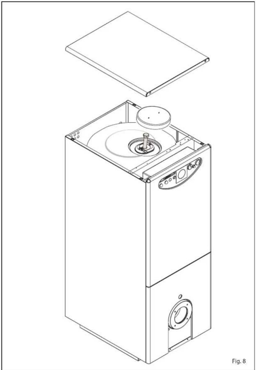
natural_image
Technical line drawing of a multi-tiered industrial machine with open lid and internal components (no text or symbols)text_image
Technical diagram of a refrigerator internal structure with numbered components and a magnified inset showing hand positioning.text_image
Technical diagram of a mechanical device with labeled components and control panelFig. 10
natural_image
Technical line drawing of a mechanical component with dimension label 'L' (no text or symbols beyond the label)Afb. 3
natural_image
Technical line drawing of a mechanical assembly with a close-up view of its internal components (no text or symbols)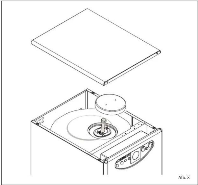
natural_image
Technical line drawing of a mechanical device with two views: top shows a flat plate, bottom shows a circular component inside a fan-like housing (no text or symbols)text_image
Technical diagram of a refrigerator internal structure with numbered components and a magnified inset showing hand positioning.text_image
Technical diagram of a mechanical device with labeled components and control panelAfb. 10
natural_image
Technical line drawing of a mechanical component with labeled dimension L (no text or symbols beyond the label)Abb. 3
1.6 BRENNER DIE MIT DEM KESSEL KOMBINIERT WERDEN KÖNNEN
( EN 267)
text_image
Technical diagram of a device interior with numbered components and labeled parts, including a central control panel and a beige 'Zein' brand logo.LEGENDE
text_image
Labeled diagram of a device control panel with numbered components and adjustment knobsAbb. 6
natural_image
Technical line drawing of an automotive electrical switch assembly with a hand operating the motor (no text or labels present)RONDO' 3/4 OF
natural_image
Technical line drawing of a mechanical component with symmetrical slots and mounting brackets (no text or symbols)RONDO' 5/6 OF
natural_image
Technical line drawing of a mechanical component with symmetrical features and mounting brackets (no text or symbols)Abb. 7
natural_image
Technical line drawing of a mechanical device with two views: top shows a flat plate, bottom shows a circular component inside a box (no text or symbols)text_image
Technical diagram of a mechanical device with labeled components and control panelAbb.10
| Lmm | Volumendm | 3 | |
| HE B4 INOX ErP | 405 | 24,0 | |
1.6 SEZNAM PRIMERNIH
GORILCEV
(EN267)
natural_image
Technical line drawing of a mechanical component with dimension L (no text or symbols)Risba 3
text_image
Technical diagram of a device interior with numbered components for identificationLEGENDA
1 Ukazna ploš Ēa
2 RoEno odzraEevanje
3 Opora 1"
4 Plaž za sonde
5 Telo kotla
6 Visoko u Ēinkovita Ērpalka grelnika
7 Kontrolni ventil
8 Avtomatski odzra Ėevalni ventil
9 Presostat za vodo
10 Grelnik 110 litrov
Risba 4/a
2 INSTALACIJA
2.1 KURILNICA
natural_image
Technical line drawing of a mechanical assembly with a close-up inset showing internal components (no text or symbols)odmaknjene turbolatorje na svoje mesto.
natural_image
Technical line drawing of a mechanical device with a central rotating disc and surrounding components (no text or symbols)text_image
Technical diagram of a refrigerator internal structure with numbered components and a hand gesture indicating assembly or repair.v gorilniku.
Gorilnik se redno priæge a se takoj ugasne
- Pregledati plamen, uravnavo zra- ka in delovanje naprave.
3.5 OPOZORILA UPORABNIKU
text_image
Technical diagram of an internal device with numbered components, likely a control panel or industrial enclosure.ΥΠΟΜΝΗΜΑ
natural_image
Technical line drawing of a mechanical assembly with a hand holding a tool, alongside a detailed close-up of the internal components (no text or symbols)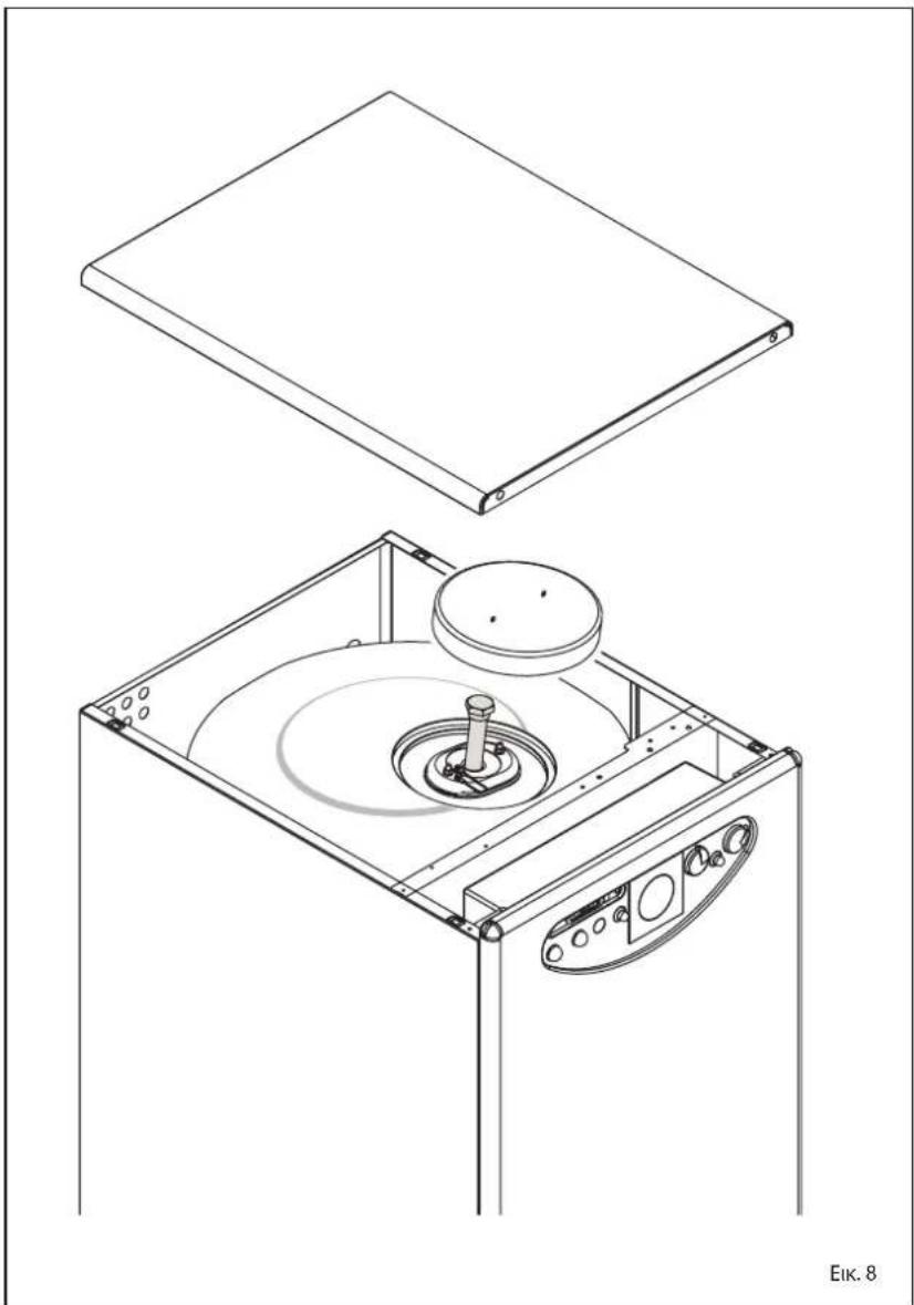
natural_image
Technical line drawing of a mechanical device with open lid and internal components (no text or symbols)text_image
Technical diagram of an open refrigerator internal structure with numbered components and a magnified inset showing hand positioning.επικίνδυνη.