
CMAD3 - Photo Accessories SONY - Free user manual and instructions
Find the device manual for free CMAD3 SONY in PDF.
| Product type | Camera adapter for AC/DC power supply |
| Brand | Sony |
| Model | CMA-D3 / CMA-D3CE |
| Dimensions (W × H × D) | 210 × 44 × 210 mm |
| Weight | Approx. 1.4 kg |
| Mains power | 100-240 V AC, 50/60 Hz |
| DC power | 11-15 V DC (30 W min.) |
| Power consumption | Approx. 22 W (AC) / 15 W (DC) |
| Operating temperature | -5°C to +45°C |
| Camera connector | 26-pin female bayonet type |
| Video outputs | G/Y OUT, B/C OUT, R/VBS OUT (BNC) |
| Sync inputs/outputs | HD and VD/SYNC (BNC), IN/OUT selector |
| Remote connector | Mini DIN 8-pin (RM-C950 optional) |
| Cable compensation | Rotary selector: 0, 25, 50, 75, 100 m |
| Max. camera cable length | 100 m (CCZ-A100) |
| Maintenance | Dry soft cloth; mild detergent if necessary |
| Safety | Mandatory grounding; do not expose to moisture |
| Included accessories | Power cord, instruction manual |
| Optional accessories | RM-C950 remote control unit, CCZ-A2/5/10/25/50/100 cables |
Frequently Asked Questions - CMAD3 SONY
User questions about CMAD3 SONY
0 question about this device. Answer the ones you know or ask your own.
Ask a new question about this device
Download the instructions for your Photo Accessories in PDF format for free! Find your manual CMAD3 - SONY and take your electronic device back in hand. On this page are published all the documents necessary for the use of your device. CMAD3 by SONY.
USER MANUAL CMAD3 SONY
© 2000 Sony Corporation
日本語
安全のために
To reduce the risk of fire or electric shock, do not expose this apparatus to rain or moisture.
To avoid electrical shock, do not open the cabinet. Refer servicing to qualified personnel only.
THIS APPARATUS MUST BE EARTHED.

This symbol is intended to alert the user to the presence of uninsulated “dangerous voltage” within the product’s enclosure that may be of sufficient magnitude to constitute a risk of electric shock to persons.

This symbol is intended to alert the user to the presence of important operating and maintenance (servicing) instructions in the literature accompanying the appliance.
IMPORTANT
The nameplate is located on the bottom.
CAUTION
The apparatus shall not be exposed to dripping or splashing and no objects filled with liquid, such as vases, shall be placed on the apparatus.
For the customers in Europe
This product with the CE marking complies with both the EMC Directive and the Low Voltage Directive issued by the Commission of the European Community.
Compliance with these directives implies conformity to the following European standards:
• EN60065: Product Safety
• EN55103-1: Electromagnetic Interference (Emission)
- EN55103-2: Electromagnetic Susceptibility (Immunity)
This product is intended for use in the following
Electromagnetic Environment(s):
E1 (residential), E2 (commercial and light industrial), E3 (urban outdoors) and E4 (controlled EMC environment, ex. TV studio)
Owner's Record
The model and serial numbers are located at the bottom. Record these numbers in the spaces provided below. Refer to these numbers whenever you call upon your Sony dealer regarding this product.
Model No. ____ Serial No. ____
For the customers in the U.S.A.
This equipment has been tested and found to comply with the limits for a Class A digital device, pursuant to Part 15 of the FCC Rules. These limits are designed to provide reasonable protection against harmful interference when the equipment is operated in a commercial environment. This equipment generates, uses, and can radiate radio frequency energy and, if not installed and used in accordance with the instruction manual, may cause harmful interference to radio communications. Operation of this equipment in a residential area is likely to cause harmful interference in which case the user will be required to correct the interference at his own expense.
You are cautioned that any changes or modifications not expressly approved in this manual could void your authority to operate this equipment.
All interface cables used to connect peripherals must be shielded in order to comply with the limits for a digital device pursuant to Subpart B of Part 15 of FCC Rules.
Important Safety Instructions
- Read these instructions.
- Keep these instructions.
- Heed all warnings.
- Follow all instructions.
- Do not use this apparatus near water.
- Clean only with dry cloth.
- Do not block any ventilation openings. Install in accordance with the manufacturer's instructions.
- Do not install near any heat sources such as radiators, heat registers, stoves, or other apparatus (including amplifiers) that produce heat.
- Do not defeat the safety purpose of the polarized or grounding-type plug. A polarized plug has two blades with one wider than the other. A grounding type plug has two blades and a third grounding prong. The wide blade or the third prong are provided for your safety. If the provided plug does not fit into your outlet, consult an electrician for replacement of the obsolete outlet.
- Protect the power cord from being walked on or pinched particularly at plugs, convenience receptacles, and the point where they exit from the apparatus.
- Only use attachments/accessories specified by the manufacturer.
- Use only with the cart, stand, tripod, bracket, or table specified by the manufacturer, or sold with the apparatus. When a cart is used, use caution when moving the cart/apparatus combination to avoid injury from tip-over.

- Unplug this apparatus during lightning storms or when unused for long periods of time.
- Refer all servicing to qualified service personnel. Servicing is required when the apparatus has been damaged in any way, such as power-supply cord or plug is damaged, liquid has been spilled or objects have fallen into the apparatus, the apparatus has been exposed to rain or moisture, does not operate normally, or has been dropped.
For the customers in Europe
The manufacturer of this product is Sony Corporation, 1-7-1 Konan, Minato-ku, Tokyo, Japan.
The Authorized Representative for EMC and product safety is Sony Deutschland GmbH, Hedelfinger Strasse 61, 70327 Stuttgart, Germany. For any service or guarantee matters please refer to the addresses given in separate service or guarantee documents.
Overview
The CMA-D3/D3CE camera adaptor is designed to operate the Sony DXC-390/390P 3CCD color video camera on an AC or DC power supply.
As the camera adaptor can be connected to the video camera using the CCMC-3MZ camera cable and a CCZ-A series camera cable extendable up to 100 m, the video camera can be installed a considerable distance from a control room.
About this manual
This manual applies to both the CMA-D3 and CMA-D3CE. The CMA-D3 is designed for the NTSC color system and can be connected to a DXC-390 video camera. The CMA-D3CE is for the PAL color system and can be connected to a DXC-390P video camera. The operating instructions for both camera adaptors are the same.
Table of Contents
Precautions 6
Safty Precautions 6
Handling Precautions 6
Location and Functions of Parts 8
Front Panel 8
Rear Panel 9
Connections ......12
Outline 12
Basic System Configuration for the DXC-390/390P...13
Connecting to a Computer 14
Specifications 15
Precautions
Safety Precautions
Power supply
- The unit is designed for operation on a power supply meeting the requirements indicated in the “Specifications” on page 15 (GB).
- Do not drop or place heavy objects on the power cord. If the power cord is damaged, turn off the power immediately. It is dangerous to use the unit with a damaged power cord.
- Disconnect the power cord from the AC outlet by grasping the plug, not by pulling the cord.
- Do not touch the AC power plug with a wet hand.
Keep foreign objects out of the cabinet
Dropping flammable or metal objects into the cabinet, or spilling liquids nearby can lead to accidents.
In case of malfunctions
If you notice any unusual sound or smell, or smoke, turn off the power immediately, disconnect the power supply and contact your Sony dealer.
Handling Precautions
Location
Do not store or use the unit under any of the following conditions.
• In excessive heat or cold
• In direct sunlight or near a heater
• In damp or dusty locations
• In locations subject to vibrations
• Near strong magnetic fields
- Near a television or radio station generating strong radio frequency energy
Protect from impact
Do not drop the unit or subject it to severe shocks.
Do not place the unit on an unstable base.
Use of the DC power supply
- Use a DC power supply capable of supplying constant voltage of 30 W or more.
- As the power switch of this unit does not operate on DC, install the power switch and fuse on the DC power source for safety.
- When connecting the DC power cable to the DC 15 V IN connector, take special care with the following:
- use a DC power cable of a sufficient current capacity.
- align the polarities correctly.
- make sure that there is no loose connection or short-circuit on the conductors.
Ventilation
To prevent internal heat buildup, do not block air circulation around the unit.
Transportation
When transporting the unit, repack it as originally packed at the factory or in materials equal in quality.
Cleaning
Clean the cabinet and panels by wiping with a soft, dry cloth. For severe stains, moisten the cloth with a small amount of neutral solvent, and finish by wiping with a dry cloth. Do not use alcohol, benzine, thinner or volatile liquids, as these may discolor or damage the cabinet surface.
Location and Functions of Parts
Front Panel
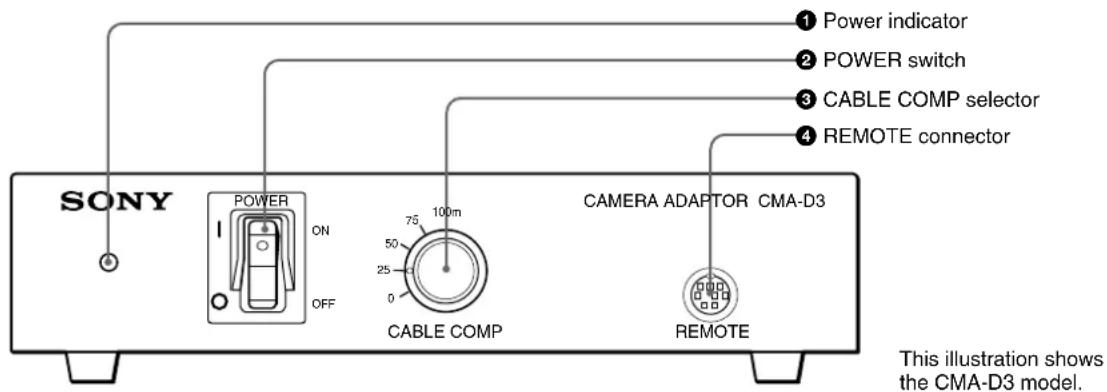
①Power indicator
For AC operation, the indicator lights when you set the POWER switch ② to ON.
For DC operation, it lights when you supply power to the DC 15V IN connector on the rear panel.
② POWER switch
For AC operation, set the switch to ON to turn on the power of the unit.
Note
The POWER switch does not operate when the DC/AC SELECT switch is set to DC.
③CABLE COMP (cable compensation) selector
Set the selector to the appropriate position according to the connected cable length.
④REMOTE (remote control) connector (mini DIN, 8-pin)
Connect to the RM-C950 remote control unit (not supplied).
Rear Panel
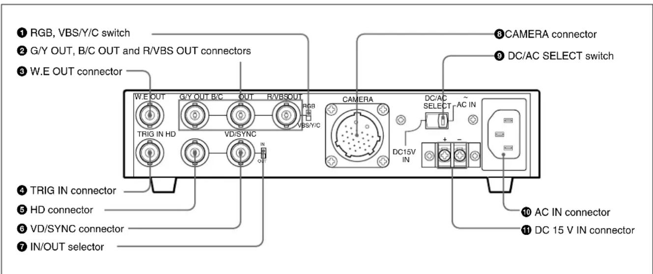
①RGB, VBS/Y/C switch
Set the switch to RGB to output the sync signal from the G/Y OUT, B/C OUT and R/VBS OUT connectors ②.
Set the switch to VBS/Y/C to output the VBS or Y/C signal from these connectors.
②G/Y OUT, B/C OUT and R/VBS OUT (video signal output) connectors (BNC type)
Output the video signal (RGB or Y/C/VBS) supplied from the video camera.
③W.E OUT (Write Enable pulse output) connector (BNC type)
Outputs the WE pulse to communicate the timing to store the image on an external frame memory, etc.
For detailed information, read the instruction manual of the DXC-390/390P.
④ TRIG IN (trigger input) connector (BNC type)
Connects to a commercially available slave unit in strobe mode by converting the connector of the slave unit into BNC type.
For detailed information, read the instruction manual of the DXC-390/390P.
⑤ HD (horizontal deflection) input/output connector (BNC type)
Inputs or outputs the HD signal. Input or output can be selected by setting the IN/OUT selector ⑦.
⑥ VD/SYNC (vertical deflection/sync) input/output connector (BNC type)
Inputs or outputs the vertical deflection signal or sync signal. Input or output can be selected by setting the IN/OUT selector 7.
The type of sync signal is set on the SYSTEM menu of the video camera.
⑦IN/OUT (sync input/output) selector
Set to IN to use the HD connector ⑤ and VD/SYNC connector ⑥ as inputs, and to OUT to use them as outputs. Set to OUT when external sync is not used.
10 (GB)
Using the HD and VD/SYNC connectors
The following shows how to use the HD and VD/SYNC connectors combined with the menu setting on the video camera and the IN/OUT selector on this unit.
| Purpose | Menu setting on camera | IN/OUT selector setting | Function of connector | |
| HD | VD/SYNC | |||
| To use HD and VD signals for external sync | Any | IN | HD signal input | VD signal input |
| To use VBS signal for external sync | Any | IN | No signal input | VBS signal input |
| To use HD and VD signals output from the camera | Set SIGNAL to HD/VD. | OUT | HD signal output | VD signal output |
| To use SYNC signal output from the camera | Set SIGNAL to C. SYNC. | OUT | No signal output | SYNC signal output |
⑧CAMERA connector (26-pin)
Connect to the DXC-390/390P video camera using the CCMC-3MZ camera cable. To extend the cable, use the CCMC-3MZ and CCZ-A series camera cables.
Pin assignment
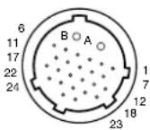
| Pin No. | Signal | Pin No. | Signal |
| A Power | output | 12 WE pulse input | |
| B GND | 13 Control | ||
| 1 Trigger | output | 14 | — |
| 2 GND | 15 | — | |
| 3 GND | 16 GND | ||
| 4 G/Y input | 17 | — | |
| 5 R/VBS | input | 18 HD input/output | |
| 6 GND | 19 GND | ||
| 7 B/C input | 20 | — | |
| 8 GND | 21 VD/SYNC input/output | ||
| 9 | — | 22 | — |
| 10 | — | 23 | — |
| 11 | — | 24 | — |
⑨DC/AC SELECT switch
Set to the right position (AC IN) to operate the video camera on the AC power supply connected to the AC IN connector. Set to the left position (DC 15V IN) to operate the video camera on the DC power supply connected to the DC 15V IN connector.
⑩ AC IN connector
Connect to an AC outlet using the AC power cord (supplied).
⑪DC 15V IN connector
Connect to the DC power supply.
Connections
Outline
Applicable cameras
You can connect the following Sony video camera to the unit.
• 3CCD color video camera DXC-390/390P
Usable camera cables
The following camera cables can be used to connect the unit to a video camera.
- CCMC-3MZ (12-pin, D-sub 9-pin, mini DIN 8-pin and BNC 26-pin) (CCZZ-1E cable adaptor supplied)
- CCZ-A2/A5/A10/A25/A50/A100 (26-pin 26-pin)
Set the CABLE COMP selector on the front panel to the appropriate position according to the camera cable length.
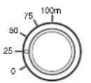
CABLE COMP
| Cable length | Selector setting |
| 10 m or less | 0 |
| Approx. 25 m | 25 |
| Approx. 50 m | 50 |
| Approx. 75 m | 75 |
| Approx. 100 m | 100 |
Notes
- If your cable length is not indicated in the table, set the selector to the position for a closer length. Do not use a cable of more than 100m .
- For DC operation, the usable cable length is limited by the supplied voltage. If you use the camera cable of 50m or longer, connect a 11.5 to 15V DC power supply.
Power supply
The unit operates on either AC or DC power supply.
AC power
Connect the AC power cord (supplied) to an AC outlet and set the DC/AC SELECT switch on the rear panel to AC IN (right position). You can turn on and off the unit with the POWER switch on the front panel.
DC power
Connect a DC external power source to the DC 15V IN connector and set the DC/AC SELECT switch on the rear panel to DC 15V IN (left position).
The power indicator lights when power is supplied to the DC 15V IN connector. (The POWER switch on this unit does not operate.)
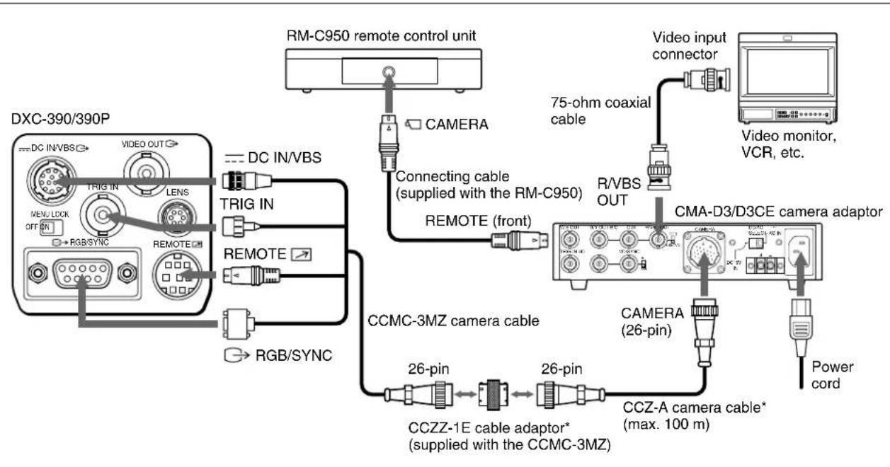
Basic System Configuration for the DXC-390/390P
Note
Turn off the power to all the units before making any connections.
flowchart
graph TD
    A["DXC-390/390P"] --> B["TRIG IN"]
    B --> C["TRIG OUT"]
    C --> D["RGB/SYNC"]
    D --> E["REMOTE"]
    E --> F["REMOTE"]
    F --> G["TRIG IN"]
    G --> H["DC IN/VBS"]
    H --> I["DMC-C950 remote control unit"]
    I --> J["CAMERA"]
    J --> K["Connecting cable (supplied with the RM-C950)"]
    K --> L["REMOTE (front)"]
    L --> M["75-ohm coaxial cable"]
    M --> N["Video input connector"]
    N --> O["CMA-D3/D3CE camera adaptor"]
    O --> P["CAMERA (26-pin)"]
    P --> Q["CCZ-A camera cable* (max. 100 m)"]
    Q --> R["Power cord"]
    R --> S["CAMCA-3MZ camera cable"]
    S --> T["CCZZ-1E cable adaptor* (supplied with the CCMC-3MZ)"]
    T --> U["26-pin"]
    U --> V["CCZ-A cable*"]
    V --> W["Power cord"]
* To extend the cable, connect the CCMC-3MZ camera cable to the CCZ-A camera cable using the cable adaptor supplied with the CCMC-3MZ.
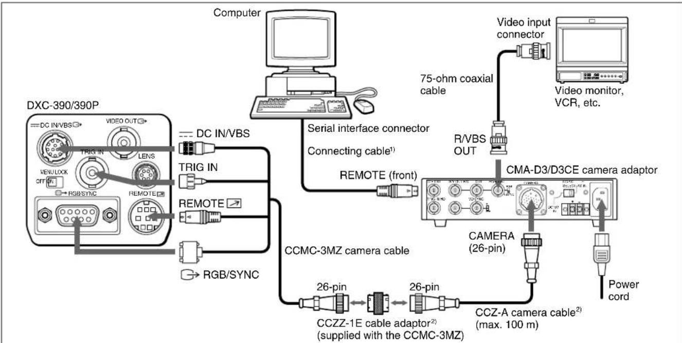
Connecting to a Computer
The following is a connection for controlling the camera with a computer using an RS-232C command.
For details on RS-232C protocols and cables for connection to a computer, contact your authorized Sony dealer.
flowchart
graph TD
    A["DXC-390/390P"] -->|DC IN/VBS| B["Computer"]
    A -->|TRIG IN| C["DRAM"]
    A -->|TRIG IN| D["USB"]
    A -->|TRIG IN| E["USB"]
    A -->|RGB/SYNC| F["USB"]
    A -->|RGB/SYNC| G["USB"]
    A --> H["Serial interface connector"]
    H --> I["Connecting cable1"]
    I --> J["REMOTE (front)"]
    J --> K["CMA-D3/D3CE camera adaptor"]
    K --> L["CAMERA (26-pin)"]
    L --> M["Power cord"]
    K --> N["CCZ-A camera cable2 (max. 100 m)"]
    K --> O["CCZZ-1E cable adaptor2 (supplied with the CCMC-3MZ)"]
    O --> P["26-pin"]
    P --> Q["CCMC-3MZ camera cable"]
    K --> R["75-ohm coaxial cable"]
    R --> S["Video input connector"]
    S --> T["Video monitor, VCR, etc."]
1) Use the shielded connecting cable for connecting to a computer.
2) To extend the cable, connect the CCMC-3MZ camera cable to the CCZ-A camera cable using the cable adaptor supplied with the CCMC-3MZ.
Specifications
General
Power requirements
CMA-D3: 100 V to 120 V AC, 50/60 Hz
CMA-D3CE: 100 V to 240 V AC, 50/60 Hz
11 to 15 V DC
DC output 15 V DC, 0.8 A (on AC operation)
DC voltage specified by the DC power supply (output from the CAMERA connector)
Power consumption
Approx. 22 W (on AC operation)
Approx. 15 W (on DC operation)
(including the power consumption of the DXC-390/390P video camera)
Peak inrush current
Power ON, current probe method: 60 A (240 V)
Hot switching inrush current, measured in accordance with European standard EN55103-1: 15 A (230 V)
Operating temperature
-5^ to +45^ (23°F to 113°F)
Storage temperature
-20^ to +60^ (-4^ to +140^)
Dimensions 210 × 44 × 210 mm ( 8^3/8 × 1^3/4 × 8^3/_8 inches) (w/h/d) (not including the projecting parts)
Mass Approx. 1.4 kg (3 lb 1 oz)
Inputs/Outputs
CAMERA connector
26-pin female, bayonet-lock type DC power output, RGB or VBS/Y/C video input, sync input/output, trigger output, WE pulse input, single-line serial communication input/output
Video output connectors
G/Y OUT: BNC type
1.0 Vp-p (G: SYNC ON)
75 ohms, SYNC ON/OFF switchable (G)
B/C OUT: BNC type
1.0 Vp-p (B: SYNC ON) or 0.3 Vp-p (PAL
C Burst), 0.286 Vp-p (NTSC C Burst), 75 ohms, SYNC ON/OFF switchable (B)
R/VBS OUT: BNC type
1.0 Vp-p (R: SYNC ON), 75 ohms, SYNC ON/OFF switchable (R)
(Continued)
Specifications
Sync input/output connectors
HD: BNC type
Input: 2–4 Vp-p, 75 ohms (with built-in
terminator)
Output: 2 Vp-p, 75 ohms
VD/SYNC: BNC type
Input: 2–4 Vp-p (VD) or 1 Vp-p (VBS)
75 ohms (with built-in terminator)
Output: 2 Vp-p, 75 ohms
Trigger input connector
TRIG IN: BNC type
TTL level
WE pulse output connector
W.E OUT: BNC type
TTL level, positive/negative
Remote control connector
Supplied accessories
AC power cord (1)
Operating Instructions (1)
Optional accessories
Remote control unit RM-C950
Camera cables CCMC-3MZ (3 m, 9.8 ft)
CCZ-A2 (2 m, 6.5 ft)
CCZ-A5 (5 m, 16.5 ft)
CCZ-A10 (10 m, 33 ft)
CCZ-A25 (25 m, 82 ft)
CCZ-A50 (50 m, 164 ft)
CCZ-A100 (100 m, 330 ft)
Design and specifications are subject to change without notice.
Français
AVERTISSEMENT
1,0 Vcc (G: SYNC ON), 75 ohms, commutable SYNC ON/OFF (G)
B/C OUT: type BNC
1,0 Vcc (B: SYNC ON) ou 0,3 Vcc (PAL C
Salve), 0,286 Vcc (NTSC C Salve),
75 ohms, commutable SYNC ON/OFF (B)
R/VBS OUT: type BNC
1,0 Vcc (R: SYNC ON), 75 ohms, commutable SYNC ON/OFF (R)
REMOTE: Mini-DIN, 8polig
Sonderzubehör
CCZ-A10 (10 m, 33 pies)
CCZ-A25 (25 m, 82 pies)
CCZ-A50 (50 m, 164 pies)
CCZ-A100 (100 m, 330 pies)
