EX752M - Power Supply Aim TTi - Free user manual and instructions
Find the device manual for free EX752M Aim TTi in PDF.
| Product type | Dual output laboratory power supply |
| Brand | Aim TTi |
| Model | EX752M |
| Voltage ranges | 0-75 V (mode A and B), 0-150 V (mode C) |
| Current ranges | 0-2 A (mode A and C), 0-4 A (mode B) |
| Mains supply | 115 V or 230 V universal, 50/60 Hz |
| Fuse | 10 A 250 V HBC time-delay (T), 5×20 mm |
| Operating modes | Independent (A), parallel (B), series (C) |
| Protection | Short circuits, reverse voltage, external overvoltage (85 V modes A/B, 170 V mode C) |
| Safety class | Class 1 per IEC, conforms to EN61010-1 |
| Ground connection | Mandatory for safety |
| Operating temperature | 5 °C to 40 °C, 20-80 % RH (non-condensing) |
| Ventilation | Convection cooling, do not obstruct |
| Cleaning | Slightly damp soft cloth, no solvents |
| Maintenance | Reserved for qualified personnel, fuse user-replaceable |
| Supplied accessories | Mains cord, user manual |
Frequently Asked Questions - EX752M Aim TTi
User questions about EX752M Aim TTi
0 question about this device. Answer the ones you know or ask your own.
Ask a new question about this device
Download the instructions for your Power Supply in PDF format for free! Find your manual EX752M - Aim TTi and take your electronic device back in hand. On this page are published all the documents necessary for the use of your device. EX752M by Aim TTi.
USER MANUAL EX752M Aim TTi
THURLBY THANDAR INSTRUMENTS
Table of Contents
Introduction 2
Specification 2
Safety 4
Installation 5
Connections 5
Operation 6
Maintenance 8
Instructions en Francais 9
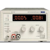
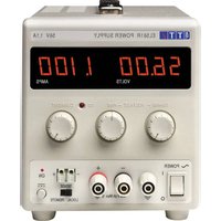
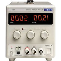
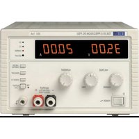
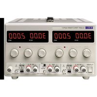
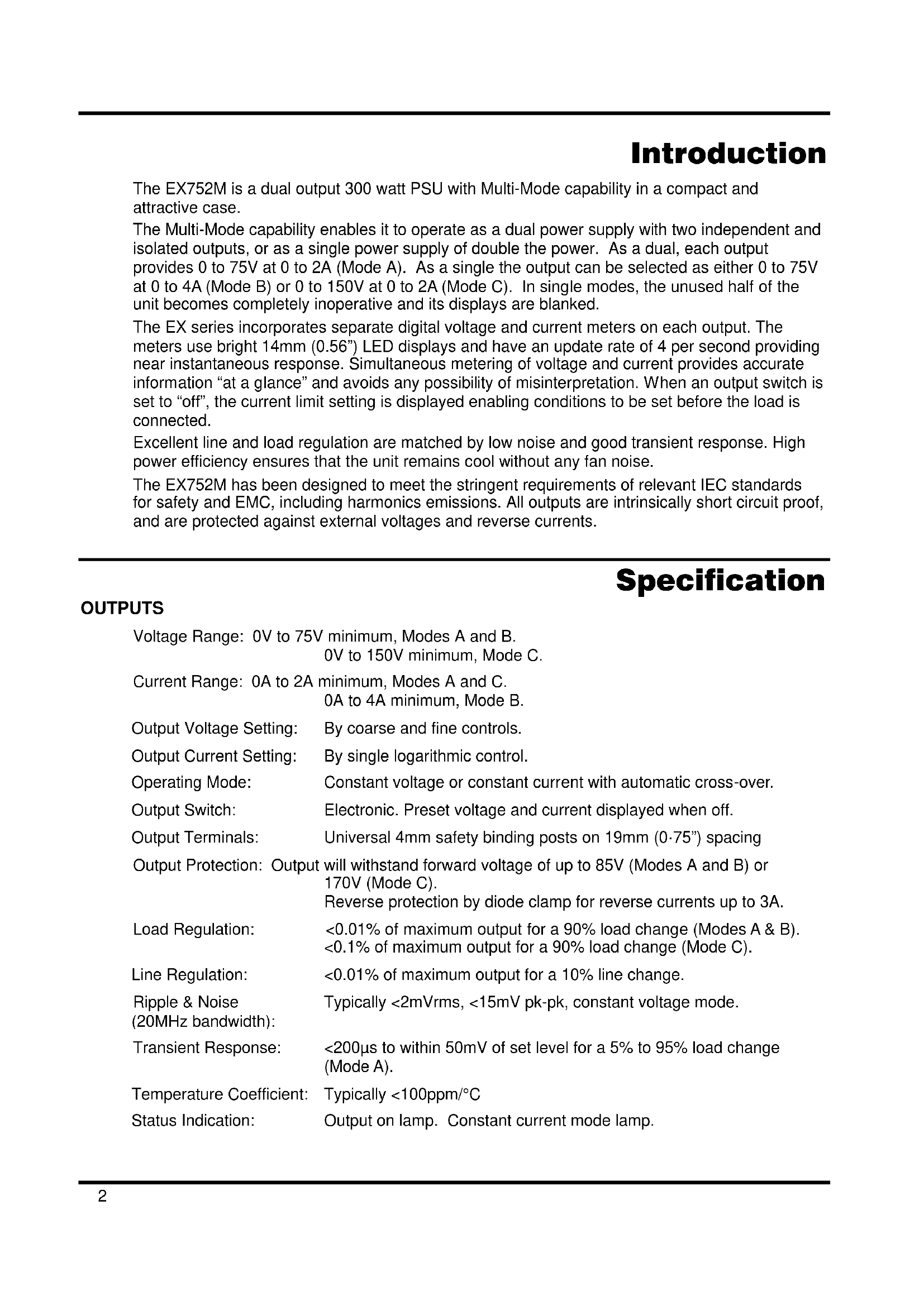
The EX752M is a dual output 300 watt PSU with Multi-Mode capability in a compact and attractive case.
The Multi-Mode capability enables it to operate as a dual power supply with two independent and isolated outputs, or as a single power supply of double the power. As a dual, each output provides 0 to 75V at 0 to 2A (Mode A). As a single the output can be selected as either 0 to 75V at 0 to 4A (Mode B) or 0 to 150V at 0 to 2A (Mode C). In single modes, the unused half of the unit becomes completely inoperative and its displays are blanked.
The EX series incorporates separate digital voltage and current meters on each output. The meters use bright 14mm (0.56") LED displays and have an update rate of 4 per second providing near instantaneous response. Simultaneous metering of voltage and current provides accurate information "at a glance" and avoids any possibility of misinterpretation. When an output switch is set to "off", the current limit setting is displayed enabling conditions to be set before the load is connected.
Excellent line and load regulation are matched by low noise and good transient response. High power efficiency ensures that the unit remains cool without any fan noise.
The EX752M has been designed to meet the stringent requirements of relevant IEC standards for safety and EMC, including harmonics emissions. All outputs are intrinsically short circuit proof, and are protected against external voltages and reverse currents.
Specification
OUTPUTS
Voltage Range: 0V to 75V minimum, Modes A and B.
0V to 150V minimum, Mode C.
Current Range: 0A to 2A minimum, Modes A and C.
0A to 4A minimum, Mode B.
Output Voltage Setting: By coarse and fine controls.
Output Current Setting: By single logarithmic control.
Operating Mode: Constant voltage or constant current with automatic cross-over.
Output Switch: Electronic. Preset voltage and current displayed when off.
Output Terminals: Universal 4mm safety binding posts on 19mm (0.75") spacing
Output Protection: Output will withstand forward voltage of up to 85V (Modes A and B) or 170V (Mode C). Reverse protection by diode clamp for reverse currents up to 3A.
Load Regulation: <0.01% of maximum output for a 90% load change (Modes A & B). <0.1% of maximum output for a 90% load change (Mode C).
Line Regulation: <0.01% of maximum output for a 10% line change.
Ripple & Noise Typically < 2mVrms < 15mV pk-pk, constant voltage mode.
(20MHz bandwidth):
Transient Response: <200μs to within 50mV of set level for a 5% to 95% load change (Mode A).
Temperature Coefficient: Typically < 100ppm / ^
Status Indication: Output on lamp. Constant current mode lamp.
OPERATING MODES
Mode Selection: By front panel rotary switch.
Mode A: Independent outputs each capable of 0-75V at 0-2A.
Mode B: Output 2 only active, 0-75V at 0-4A.
Output 1 disabled.
Mode C: Output 2 only active, 0-150V at 0-2A.
Output 1 disabled.
METER SPECIFICATIONS
Meter Types: Dual 3 digit meters with 14mm (0.56") LEDs. Reading rate 4 Hz.
Meter Resolutions: 100mV, 10mA
Meter Accuracies: Voltage 0.3% of reading ± 1 digit,
Current 0.6% of reading ± 1 digit
Operating Modes: Output 1 meters are blanked in Modes B and C.
GENERAL
AC Input: 110V-240V AC ±10%. Installation Category II.
Power Consumption: 500VA max.
Operating Range: +5^ to +40^ 20% to 80% RH.
Storage Range: -40^ to +70^ .
Environmental: Indoor use at altitudes up to 2000m, Pollution Degree 2.
Safety & EMC: Complies with EN61010-1 & EN61326-1.
For details, request the EU Declaration of Conformity for this instrument via http://www.aimtti.com/support (serial no. needed).
Size: 260 × 160 × 320 ~mm (WxHxD).
Weight: 4.3kg
Safety
This power supply is a Safety Class I instrument according to IEC classification and has been designed to meet the requirements of EN61010-1 (Safety Requirements for Electrical Equipment for Measurement, Control and Laboratory Use). It is an Installation Category II instrument intended for operation from a normal single phase supply.
This instrument has been tested in accordance with EN61010-1 and has been supplied in a safe condition. This instruction manual contains some information and warnings which have to be followed by the user to ensure safe operation and to retain the instrument in a safe condition.
This instrument has been designed for indoor use in a Pollution Degree 2 environment in the temperature range 5^ to 40^ , 20% - 80% RH (non-condensing). It may occasionally be subjected to temperatures between +5^ and -10^ without degradation of its safety. Do not operate while condensation is present.
Use of this instrument in a manner not specified by these instructions may impair the safety protection provided. Do not operate the instrument outside its rated supply voltages or environmental range.
WARNING! THIS INSTRUMENT MUST BE EARTHED
Any interruption of the mains earth conductor inside or outside the instrument will make the instrument dangerous. Intentional interruption is prohibited. The protective action must not be negated by the use of an extension cord without a protective conductor.
When the instrument is connected to its supply, terminals may be live and opening the covers or removal of parts (except those to which access can be gained by hand) is likely to expose live parts. The apparatus shall be disconnected from all voltage sources before it is opened for any adjustment, replacement, maintenance or repair. Capacitors inside the power supply may still be charged even if the power supply has been disconnected from all voltage sources but will be safely discharged about 10 minutes after switching off power.
Any adjustment, maintenance and repair of the opened instrument under voltage shall be avoided as far as possible and, if inevitable, shall be carried out only by a skilled person who is aware of the hazard involved.
If the instrument is clearly defective, has been subject to mechanical damage, excessive moisture or chemical corrosion the safety protection may be impaired and the apparatus should be withdrawn from use and returned for checking and repair.
Make sure that only fuses with the required rated current and of the specified type are used for replacement. The use of makeshift fuses and the short-circuiting of fuse holders is prohibited.
Do not wet the instrument when cleaning it.
The following symbols are used on the instrument and in this manual:

Earth (ground) terminal.
mains supply OFF.
mains supply ON.
alternating current (ac)
direct current (dc)
Caution - risk of danger. Refer to the documentation (this manual) to find out the nature of the potential hazard and any actions which have to be taken.
Installation
Mains Operating Voltage
This instrument has a universal input range and will operate from a nominal 115V or 230V mains supply without adjustment. Check that the local supply meets the AC Input requirement given in the Specification.
Mains Lead
Connect the instrument to the AC supply using the mains lead provided. Should a mains plug be required for a different mains outlet socket, a suitably rated and approved mains lead set should be used which is fitted with the required wall plug and an IEC60320 C13 connector for the instrument end. To determine the minimum current rating of the lead-set for the intended AC supply, refer to the power rating information on the equipment or in the Specification.
WARNING! THIS INSTRUMENT MUST BE EARTHED.
Any interruption of the mains earth conductor inside or outside the instrument will make the instrument dangerous. Intentional interruption is prohibited.
Ventilation
The power supply is very efficient but nevertheless can generate significant heat at full power. The supply relies on convection cooling only and it is therefore important that ventilation is never restricted if performance and safety are to be maintained.
Connections
All connections are made from the front panel.
The load should be connected to the positive (red) and negative (black) terminals marked OUTPUT. Connect to one or both outputs as appropriate for the selected Mode, see Operation section.

Warning! Voltages above 70Vdc are hazardous live according to EN 61010-1 and great care must be taken when using the power supply at voltages above this level.
The universal safety binding posts used for the output meet the requirements for reinforced insulation for voltages up to 250Vdc because creepage and clearance to the terminal contacts is >2.5mm even with the binding post fully open. However, it is highly recommended that the binding posts are usually fully tightened and that connections are only made using leads fitted with fixed-shroud 4mm safety plugs. Make sure that the circuit to which connections are made is appropriately insulated; no accessible parts of the external circuit should become hazardous live in normal or single fault condition as defined by EN61010-1.

Always make connections to the instrument with the OUTPUT off.
The terminal marked 12 is connected to the chassis and safety earth ground.
Operation
The operation of both outputs is identical in Mode A (independent mode); the following description applies to both. In Mode B and Mode C only Output 2 is active and Output 1 is disabled; the description therefore only applies to Output 2, see Mode Selection section.
Setting Up the Output
With the POWER switch on (I) and the output off the output voltage and current limit can be accurately preset using the VOLTAGE and CURRENT controls; the left-hand meter shows the set voltage and the right-hand meter shows the set maximum current.
When the output switch is switched on, the ON lamp lights; the left-hand meter now shows the actual voltage and the right-hand meter the actual load current.
Constant Voltage
The output voltage is adjusted using the coarse and fine VOLTAGE controls; the CURRENT control sets the maximum current that can be supplied.
Constant Current
If the load resistance is low enough such that, at the output voltage set, a current greater than the current limit setting would flow, the power supply will automatically move into constant current operation. The current output is adjusted by the CURRENT control and the VOLTAGE controls set the maximum voltage that can be generated.
The CC lamp lights to show constant current mode.
Instantaneous Current Output
The current limit control can be set to limit the continuous output current to levels down to 10mA . However, in common with all precision bench power supplies, a capacitor is connected across the output to maintain stability and good transient response. This capacitor charges to the output voltage and short-circuiting of the output will produce a current pulse as the capacitor discharges which is independent of the current limit setting.
Mode Selection
The three operating modes are selected by the front panel rotary switch situated between the terminals.

Caution. Turn both outputs off before changing mode. Possible damage to the circuit being powered, and to the unit itself, may occur if the mode is switched with either output still on.
Mode A: With the switch in this position the outputs operate independently and are isolated from one another. The voltage range on each output is 0-75V and the current range 0-2A.
Mode B: With the switch in this position only Output 2 is active; the voltage range is 0-75V and the current range is 0-4A. The controls of Output 1 are inoperative and the display is blanked. The terminals of Output 1 are isolated from those of Output 2.
Note that with the output switch of Output 1 in the 'ON' position the Output lamp still lights but the terminals remain open-circuit.
Note also that the range and scaling of the current limit control doubles when changing from Mode A to Mode B, i.e. with the control set for a 1.5A limit in Mode A, the limit becomes 3A in Mode B. To avoid possible damage to the circuit being tested the outputs should be switched off before the mode is changed and the current limit set to the desired value before the output is switched on.
Mode C: With the switch in this position only Output 2 is active; the voltage range is 0-150V and the current range is 0-2A. The controls of Output 1 are inoperative and the display is blanked. The red terminal of Output 1 is isolated but the black terminal remains connected internally to the black terminal of Output 2.
Note that when the output switch of Output 1 is in the 'ON' position the Output lamp still lights but the red terminal remains open-circuit.
Note also that the range and scaling of the voltage controls of Output 2 double when changing from Mode B to Mode C, i.e. with the controls set for 60V in Mode B the output voltage becomes 120V in Mode C. Care should therefore be taken to ensure that the outputs are switched off before the mode is changed and that the output is set to the correct voltage before it is switched on.
Protection
The output has intrinsic short-circuit protection and is protected from reverse voltages by a diode; the continuous reverse current must not exceed 3 Amps, although transients can be much higher.
The output is protected against externally applied forward voltages of up to 85V (Modes A and B) or 170V (Mode C).
Connection to the Load
The load should be connected to the positive (red) and negative (black) OUTPUT terminals. Both are fully floating and either can be connected to ground.

Warning! Voltages above 70Vdc are hazardous live according to EN 61010-1 and great care must be taken when using the power supply at voltages above this level.
It is highly recommended that connections are only made using leads fitted with fixedshroud 4mm safety plugs. Make sure that the circuit to which connections are made is appropriately insulated; no accessible parts of the external circuit should become hazardous live in normal or single fault condition as defined by EN61010-1.

Always make connections to the instrument with the OUTPUT off.
Series or Parallel Connection with Other Outputs
The outputs of the power supply are fully floating and may be used in series with other power supply units to generate high DC voltages up to 300V DC.

Warning! Voltages above 70Vdc are hazardous live according to EN 61010-1 and great care must be taken when using the power supply at voltages above this level
The maximum permissible voltage between any terminal and earth ground (12) is 300VDC; the maximum permissible voltage between either terminal of one output and any terminal of another output on the same supply is also 300VDC.

All connections to the terminals must be made with the output switched off on all units.
It should be noted that the unit can only source current and cannot sink it, thus units cannot be series connected in anti-phase.
The unit can be connected in parallel with others to produce higher currents. Where several units are connected in parallel, the output voltage will be equal to that of the unit with the highest output voltage setting until the current drawn exceeds its current limit setting, upon which the output will fall to that of the next highest setting, and so on. In constant current mode, units can be connected in parallel to provide a current equal to the sum of the current limit settings.
Maintenance
The Manufacturers or their agents overseas will provide repair for any unit developing a fault. Where owner wish to undertake their own maintenance work, this should only be done by skilled personnel in conjunction with the service manual which may be purchased directly from the Manufacturers or their agents overseas.
Fuse
The correct fuse type is:
10 Amp 250V HBC time-lag(T), 5 × 20mm .
Note that the main function of the fuse is to make the instrument safe and limit damage in the event of failure of one of the switching devices. If a fuse fails it is therefore very likely that the replacement will also blow, because the supply has developed a fault; in such circumstances the instrument will need to be returned to the manufacturer for service.
Make sure that only fuses of the required rated current and specified type are used for replacement. The use of makeshift fuses and the short-circuiting of fuse-holders is prohibited.
To replace a fuse, first disconnect the instrument from the AC supply. Remove the 6 cover securing screws and lift off the cover. Replace the fuse with one of the correct type and refit the cover.
Cleaning
If the PSU requires cleaning use a cloth that is only lightly dampened with water or a mild detergent. Polish the display window with a soft dry cloth.
WARNING! TO AVOID ELECTRIC SHOCK, OR DAMAGE TO THE PSU, NEVER ALLOW WATER TO GET INSIDE THE CASE. TO AVOID DAMAGE TO THE CASE OR DISPLAY WINDOW NEVER CLEAN WITH SOLVENTS.
courant continu (c.c.)

courant alternative (c.a.)

La energia de la combustible combustible gas (combustible gas) is a heat source in the atmosphere. It is produced by the burning of fossil fuels, such as petroleum and coal. The energy generated from the combustion of fossil fuels is called thermal energy.

Glebe Road - Huntingdon - Cambridgeshire - PE29 7DR - England (United Kingdom)
Telephone: +44 (0)1480 412451 Fax: +44 (0)1480 450409
International web site: www.aimtti.com • UK web site: www.aimtti.co.uk
Email: info@aimtti.com