B110SPCATOD2 - Surge protector Tripp Lite - Free user manual and instructions
Find the device manual for free B110SPCATOD2 Tripp Lite in PDF.

| Product Type | Outdoor PoE Inline Surge Protector |
| Brand | Tripp Lite |
| Model | B110SPCATOD2 |
| Dimensions (H x W x D) | 81 x 71 x 165 mm |
| Weight | 0.23 kg |
| Power Supply | Passive (no external power required) |
| Connectors | RJ45 female (input and output) |
| Supported PoE Standards | IEEE 802.3af, 802.3at, 802.3bt |
| Maximum PoE Power | 90 W |
| Network Speed | 10/100/1000 Mbps |
| ESD Protection (air/contact) | ±15 kV / ±8 kV |
| Lightning Protection (8/20 μs) | 10 kA / 20 kV |
| Response Time | < 1 ns |
| Operating Temperature | -40 to 70 °C |
| IP Rating | IP68 (dust and water resistant) |
| Housing Material | ABS |
| Warranty | 2 years (limited) |
| Included Accessories | Grounding wire (0.3 m), cable pins, mounting screws, cover screws, user manual |
Frequently Asked Questions - B110SPCATOD2 Tripp Lite
User questions about B110SPCATOD2 Tripp Lite
0 question about this device. Answer the ones you know or ask your own.
Ask a new question about this device
Download the instructions for your Surge protector in PDF format for free! Find your manual B110SPCATOD2 - Tripp Lite and take your electronic device back in hand. On this page are published all the documents necessary for the use of your device. B110SPCATOD2 by Tripp Lite.
USER MANUAL B110SPCATOD2 Tripp Lite
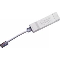
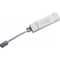
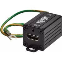
IP68-Rated Gigabit PoE Outdoor In-Line Surge Protector
Model: B110-SP-CAT-OD2
Español 13 • Français 25
Русский 37 • Deutsch 49
WARRANTY REGISTRATION
Register your product today and be automatically entered to win an ISOBAR ^® surge protector in our monthly drawing!
tripplite.com/warranty


Manufacturing Excellence.
1111 W. 35th Street, Chicago, IL 60609 USA tripplite.com/support
Copyright © 2021 Tripp Lite.
All trademarks are the property of their respective owners.
Package Includes
• B110-SP-CAT-OD2 Outdoor In-Line Surge Protector
• 18 AWG Grounding Wire – 1 ft.
• Cable Gland, 8.4 mm Diameter (x3)
• Surface Screw Anchors (x4)
• Surface Mounting Screws (x4)
- Unit Cover Screws (x4)
- Owner's Manual
Product Features
- Protects valuable indoor and outdoor PoE equipment from power surges, lightning, ESD and cable discharge events in unforgiving environments
- Complies with 802.3af, 802.3at and 802.3bt IEEE Standards
- Supports PoE devices up to 90W and Ethernet speeds up to 1 Gbps
• Meets the following IEC Regulations:
o IEC 61000-4-2 (ESD) +/- 15kV(Air), +/- 8kV(Contact)
o IEC 61000-4-5 (Lightning) 10kA (8/20μs), 20kV (8/20μs)
• Supports both Mid- and End-Span PoE
• Passive by design – no external power required
Optional Accessories
• N224-Series Cat6 Plenum-Rated Solid-Core Bulk Cable
• N046-000 Punch Down Installation Tool
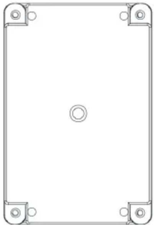
Mounting Instructions
- Locate the mounting holes on the bottom of the enclosure, as shown in Figure 1.
natural_image
Pure technical drawing of a rectangular frame with corner mounting holes and center circle (no text or symbols)Figure 1
- Securely mount the bottom portion of the enclosure to the desired outdoor location. Screw hole diameter supports mounting screws up to M3.5.
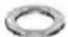
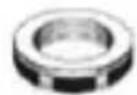
Metric Cable Gland Assembly
A
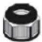
B
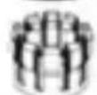
C
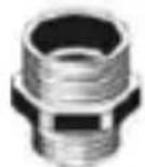
D
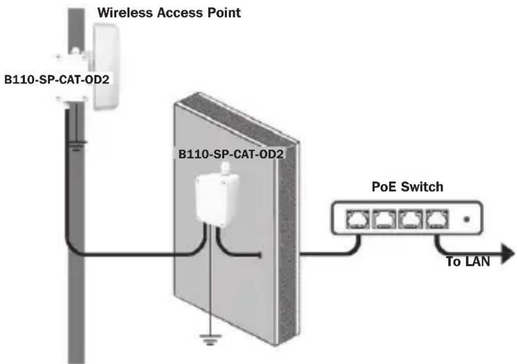
Installation
Protect indoor and outdoor edge network devices like PoE cameras or LAN access points from electrical damage by installing the B110-SP-CAT-OD2 between the source and edge network equipment.
Notes:
• Maximum cable distance between B110-SP-CAT-OD2 and source is 328 ft. (100 m).
• Maximum cable distance between B110-SP-CAT-OD2 and equipment is 328 ft. (100 m).
- For best protection performance, the total cable distance in the installation should not exceed 328 ft. (100 m).
- The B110-SP-CAT-OD2 must be grounded to function properly.
Installation
Protecting Edge-Of-Network Equipment
This installation protects your edge equipment from surge, lightning or ESD damage. To protect both the source and edge equipment, refer to section Protecting Edge-Of-Network Source and Equipment in this guide.
Note: Use standard size Cat5e, Cat6 or Cat6a cables that feature a wire gauge of 23/24 AWG. Slim category cables are not supported.
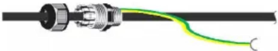
- Remove both the cap A and end nut E from one of the cable glands (refer to section Cable Gland Assembly).
- Slide the cap and remaining portion of the cable gland onto both the included grounding wire and bare-wire category cable coming from your source (ex: PoE switch) as shown:
natural_image
Diagram of a cable connector with a green-yellow curved line indicating winding or connection (no text or symbols)Note: Use standard Cat5e, Cat6 or Cat6a cables with a wire gauge of 23/24 AWG. Slim category cables are not supported.
Installation
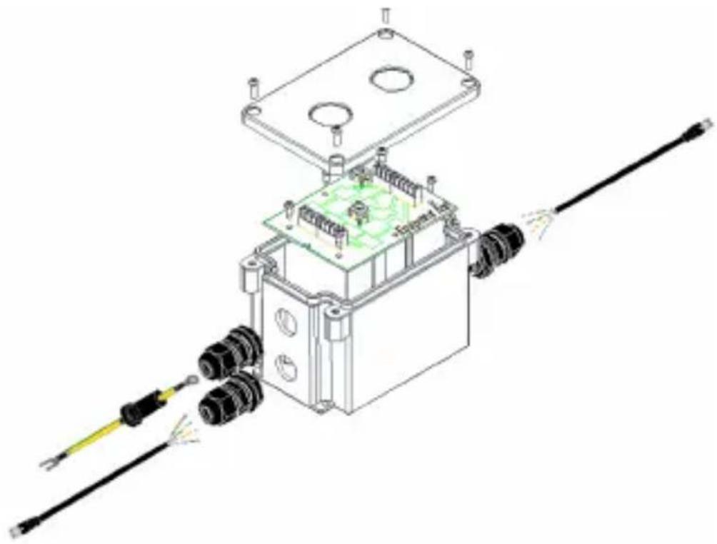
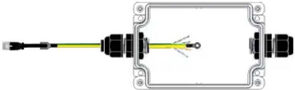
- Insert both the grounding wire and the bare-wire end of the category cable in the enclosure, making sure it is inserted on the "cable end" side.
natural_image
Technical line drawing of an electrical component with wires and a green circuit board (no text or symbols)Installation
- Screw the metric cable gland to the enclosure using the end nut D previously removed in step 1. Then, tighten the cap securely onto the cable gland.
- Using a punch down tool (such as Tripp Lite's N046-000, sold separately), connect the bare wire to the color-coded board inside the enclosure.
natural_image
Diagram of an electrical connector with a yellow cable and terminal blocks (no text or symbols)- Repeat Steps 1-3 for the equipment (ex: PoE camera) side of the enclosure without the addition of a grounding wire.
Note: To achieve the best protection performance, the Cat5e/6/6a patch cable between the equipment end of the B110-SP-CAT-OD surge protector and the equipment to be protected must not exceed 300 ft. (100 m).
natural_image
Pure electrical connector diagram without any text, numbers, or symbolsInstallation
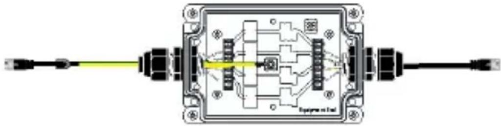
- Once both bare wires are connected, secure the PCBA board to the enclosure using the included mounting screws. Then, attach the grounding wire to the available screw on the PCBA board.
Note: Make sure you connect your source to the cable end and your PoE-compliant device to the equipment end.
natural_image
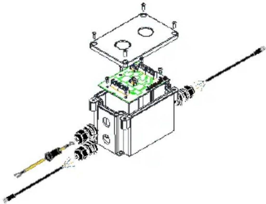
Pure electrical circuit lines without any symbols- Screw the front cover to the back portion of the enclosure using the included unit cover screws.
natural_image
Technical line drawing of a mechanical assembly with components like a housing, gears, and a tool (no text or symbols)- The connected PoE device is now protected.
Installation
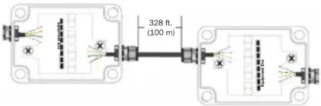
Protecting Edge-Of-Network Source and Equipment
The previous installation only protects your edge equipment from surge, lightning or ESD damage. To protect both the source and edge equipment, install two B110-SP-CAT-OD2 units in your application. A B110-SP-POE can be installed instead of a second B110-SP-CAT-OD2 to protect the source if the second unit will be installed indoors.
Note: Use standard size Cat5e, Cat6 or Cat6a cables that feature a wire gauge of 23/24 AWG. Slim category cables are not supported. Maximum cable distance between two B110-SP-CAT-OD2 units is 328 ft. (100 m).
- Install a second B110-SP-CAT-OD2 between the first B110-SP-CAT-OD2 unit and your source following steps 1-3 in Protecting Edge-Of-Network Equipment section.
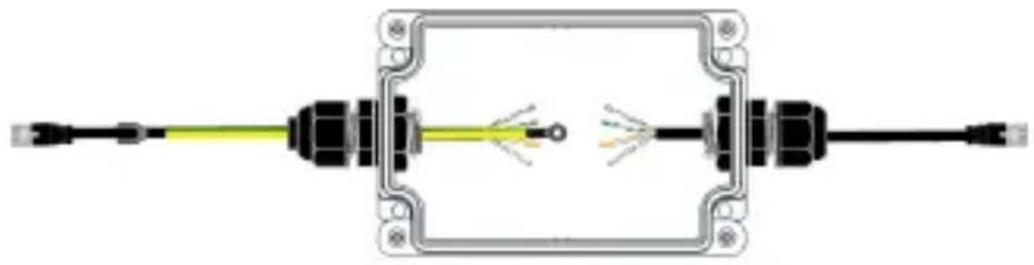
Installation
- In order to protect both the source and edge equipment, the two B110-SP-CAT-OD2 units need to be wired cable-end to cable-end as shown below.
Specifications
| Input / Output Connectors RJ45 | Female |
| ESD Protection 15kV (Air), 8kV | (Contact) |
| Lightning Protection 10kA (8/20μs) / 20kV (8/20μs) | |
| Surge Reaction Speed < 1ns | |
| Operating Temperature Range | -40°F to 158°F (-40°C to 70°C) |
| Storage Temperature Range -40°F to 194°F (-40°C to 90°C) | |
| Relative Humidity Range 0 to 95% RH, Non-Condensing | |
| IP Rating IP68 (Dust-Proof / Water-Resistant) | |
| Network Speed 10/100/1000 Mbps | |
| Max Supported PoE Wattage 90W | |
| IEEE Standards Supported 802.3af, 802.3at, 802.2bt | |
| Span Support Mid- & End-Span | |
| Material ABS | |
| Dimensions [H x W x D] 3.2 x 2.8 x 6.5 in. (81 x 71 x 165 mm) | |
| Weight 0.51 lb. (0.23 kg) | |
Warranty and Product Registration
2-Year Limited Warranty
Tripp Lite warrants its products to be free from defects in materials and workmanship for a period of two (2) years from the date of initial purchase. Tripp Lite's obligation under this warranty is limited to repairing or replacing (at its sole option) any such defective products. To obtain service under this warranty, you must obtain a Returned Material Authorization (RMA) number from Tripp Lite or an authorized Tripp Lite service center. Products must be returned to Tripp Lite or an authorized Tripp Lite service center with transportation charges prepaid and must be accompanied by a brief description of the problem encountered and proof of date and place of purchase. This warranty does not apply to equipment, which has been damaged by accident, negligence or misapplication or has been altered or modified in any way.
EXCEPT AS PROVIDED HEREIN, Tripp Lite MAKES NO WARRANTIES, EXPRESS OR IMPLIED, INCLUDING WARRANTIES OF MERCHANTABILITY AND FITNESS FOR A PARTICULAR PURPOSE. Some states do not permit limitation or exclusion of implied warranties; therefore, the aforesaid limitation(s) or exclusion(s) may not apply to the purchaser.
EXCEPT AS PROVIDED ABOVE, IN NO EVENT WILL Tripp Lite BE LIABLE FOR DIRECT, INDIRECT, SPECIAL, INCIDENTAL OR CONSEQUENTIAL DAMAGES ARISING OUT OF THE USE OF THIS PRODUCT, EVEN IF ADVISED OF THE POSSIBILITY OF SUCH
DAMAGE. Specifically, Tripp Lite is not liable for any costs, such as lost profits or revenue, loss of equipment, loss of use of equipment, loss of software, loss of data, costs of substitutes, claims by third parties, or otherwise.
Product Registration
Visit triplite.com/warranty today to register your new Tripp Lite product. You'll be automatically entered into a drawing for a chance to win a FREE Tripp Lite product!*
*No purchase necessary. Void where prohibited. Some restrictions apply. See website for details.
Use of this equipment in life support applications where failure of this equipment can reasonably be expected to cause the failure of the life support equipment or to significantly affect its safety or effectiveness is not recommended.
Tripp Lite has a policy of continuous improvement. Specifications are subject to change without notice. Photos and illustrations may differ slightly from actual products.


1111 W. 35th Street, Chicago, IL 60609 USA tripplite.com/support
12
21-02-277 93-3D64_RevA
1111 W. 35th Street, Chicago, IL 60609 EE UU
tripplite.com/support
Copyright © 2021 Tripp Lite.
natural_image
Pure technical drawing of a rectangular frame with corner mounting holes and center circle (no text or symbols)Figura 1
natural_image
Diagram of a cable connector with a green-yellow curved line extending from its end (no text or symbols)natural_image
Technical line drawing of an electrical component with wires and a green circuit board (no text or symbols)Instalación
natural_image
Diagram of an electrical connector with a yellow cable and terminal blocks (no text or symbols)natural_image
Pure electrical connector diagram showing two connectors with wires, no text or symbols presentInstalación
natural_image
Pure electrical circuit lines without any symbolsnatural_image
Technical line drawing of a mechanical assembly with gears and a central component (no text or symbols)1111 W. 35th Street, Chicago, IL 60609 USA tripplite.com/support
natural_image
Pure technical drawing of a rectangular frame with corner mounting holes and center circle (no text or symbols)Figure 1
natural_image
Diagram of a cable with connectors and a curved green-yellow line, no text or symbols presentnatural_image
Technical line drawing of an electrical component with wires and connectors (no text or symbols)Installation
natural_image
Diagram of an electrical connector with a yellow cable and terminal blocks (no text or symbols)natural_image
Pure electrical connector diagram showing internal wiring and terminal connections without any text or symbolsInstallation
natural_image
Pure electrical circuit lines without any symbolsnatural_image
Technical line drawing of a mechanical assembly with gears and a green circuit board (no text or symbols)1111 W. 35th Street, Chicago, IL 60609 USA tripplite.com/support
36
21-02-277 93-3D64_RevA
1111 W. 35th Street, Chicago, IL 60609 USA
tripplite.com/support
natural_image
Pure technical drawing of a rectangular frame with corner mounting holes and center circle (no text or symbols)Рис. 1
natural_image
Diagram of a cable with connectors and a green-yellow curved line, no text or symbols presentnatural_image
Technical line drawing of an electrical component with wires and connectors (no text or symbols)Установка
natural_image
Pure electrical connector diagram showing two connectors with wires and wiring, no text or symbols presentУстановка
natural_image
Pure electrical circuit lines without any symbolsnatural_image
Technical line drawing of an electronic device with components and wiring (no text or symbols)1111 W. 35th Street, Chicago, IL 60609 USA
tripplite.com/support
21-02-277 93-3D64_RevA
Kurzanleitung
1111 W. 35th Street, Chicago, IL 60609 USA tripplite.com/support
natural_image
Pure technical drawing of a rectangular frame with corner mounting holes and center circle (no text or symbols)Abbildung 1
natural_image
Diagram of a cable connector with a green-yellow curved line indicating winding or flow (no text or symbols)natural_image
Technical line drawing of an electrical component with wires and a green circuit board (no text or symbols)Installation
natural_image
Diagram of an electrical connector with a yellow cable and terminal blocks (no text or symbols)natural_image
Pure electrical connector diagram showing two connected modules with wires and connectors (no text or symbols)Installation
natural_image
Pure electrical circuit lines without any symbolsnatural_image
Technical line drawing of a mechanical assembly with gears and a housing (no text or symbols)1111 W. 35th Street, Chicago, IL 60609 USA tripplite.com/support
60
21-02-277 93-3D64_RevA