
B116002AINT - Distributor Tripp Lite - Free user manual and instructions
Find the device manual for free B116002AINT Tripp Lite in PDF.
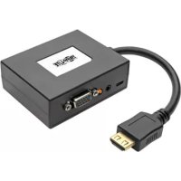
| Product Type | DVI Splitter with Signal Amplifier and Audio |
| Brand | Tripp Lite |
| Models | B116-002A, B116-002A-INT (included) |
| Number of Outputs | 2 DVI + audio outputs (model -002A) |
| Supported Resolutions | Up to 1920 x 1200 (PC) and 1080p (HD) |
| Power | External: input 100-240 V AC, 50/60 Hz, 0.35 A; output 5 V DC, 2 A |
| Power Cord Length | 1.37 m (4.5 ft) |
| Input Connectors | 1 x DVI-D female + 1 x 3.5 mm audio jack female |
| Output Connectors | 2 x DVI-D female + 2 x 3.5 mm audio jack female (per output port) |
| Maximum Source-to-Splitter Distance | 5 m (16 ft) |
| Maximum Splitter-to-Screen Distance (High Resolution) | 15 m (49 ft) |
| Maximum Splitter-to-Screen Distance (Low Resolution) | 20 m (65 ft) |
| Cascading Capability | Up to 3 levels, 64 displays max |
| HDCP/EDID/DDC Compatibility | Yes |
| Operation | Plug-and-play, no software required |
| Mounting | Wall, 19" rack, pole (kit included) |
| Power Adapters | 4 international adapters (North America, UK, Europe, Australia) |
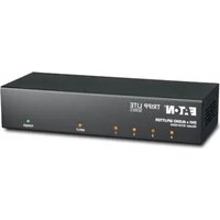
| LED Indicators | Power LED and port LEDs (input/output) |
| Compliance | TAA (Federal Trade Agreements Act) |
| Operating Temperature | 0°C to 40°C (reasonable estimate) |
| Dimensions (approx.) | Approximately 14 x 10 x 3 cm (not specified, estimated) |
| Weight (approx.) | Approximately 250 g (reasonable estimate) |
| Warranty | 1-year limited |
| Maintenance | Clean with a dry, soft cloth; do not use abrasive products |
| Optional Accessories | DVI Repeater B120-000, DVI+audio cables P560-Series, DVI cables P561-Series, audio cables P312-Series |
Frequently Asked Questions - B116002AINT Tripp Lite
User questions about B116002AINT Tripp Lite
0 question about this device. Answer the ones you know or ask your own.
Ask a new question about this device
Download the instructions for your Distributor in PDF format for free! Find your manual B116002AINT - Tripp Lite and take your electronic device back in hand. On this page are published all the documents necessary for the use of your device. B116002AINT by Tripp Lite.
USER MANUAL B116002AINT Tripp Lite
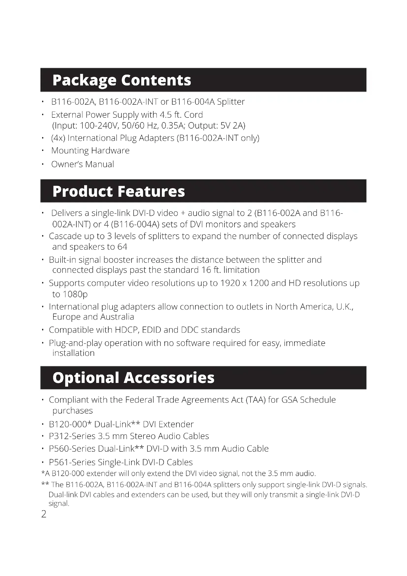
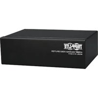
1080p DVI Splitter with Audio and Signal Booster
Models:
B116-002A
B116-002A-INT
B116-004A
Purchased product may differ from image.
Español 9
Français 17
Deutsch 25
Italiano 33
Package Contents
• B116-002A, B116-002A-INT or B116-004A Splitter
• External Power Supply with 4.5 ft. Cord (Input: 100-240V, 50/60 Hz, 0.35A; Output: 5V 2A)
• (4x) International Plug Adapters (B116-002A-INT only)
- Mounting Hardware
- Owner's Manual
Product Features
- Delivers a single-link DVI-D video + audio signal to 2 (B116-002A and B116-002A-INT) or 4 (B116-004A) sets of DVI monitors and speakers
- Cascade up to 3 levels of splitters to expand the number of connected displays and speakers to 64
- Built-in signal booster increases the distance between the splitter and connected displays past the standard 16 ft. limitation
• Supports computer video resolutions up to 1920 x 1200 and HD resolutions up to 1080p
• International plug adapters allow connection to outlets in North America, U.K., Europe and Australia - Compatible with HDCP, EDID and DDC standards
- Plug-and-play operation with no software required for easy, immediate installation
Optional Accessories
- Compliant with the Federal Trade Agreements Act (TAA) for GSA Schedule purchases
• B120-000* Dual-Link** DVI Extender
• P312-Series 3.5 mm Stereo Audio Cables
• P560-Series Dual-Link** DVI-D with 3.5 mm Audio Cable
• P561-Series Single-Link DVI-D Cables
*A B120-000 extender will only extend the DVI video signal, not the 3.5 mm audio.
** The B116-002A, B116-002A-INT and B116-004A splitters only support single-link DVI-D signals. Dual-link DVI cables and extenders can be used, but they will only transmit a single-link DVI-D signal.
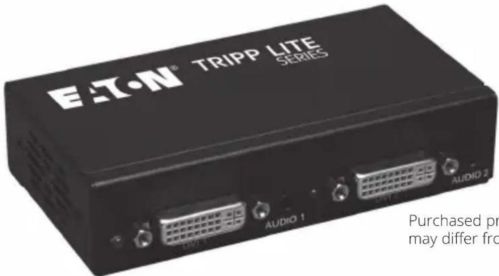
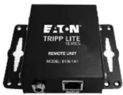
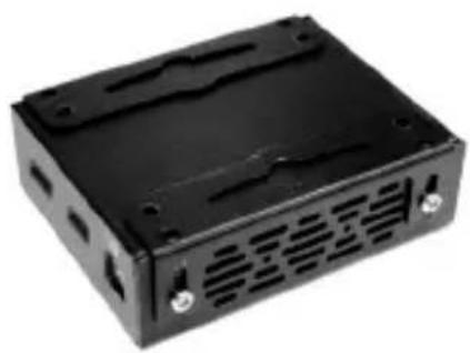
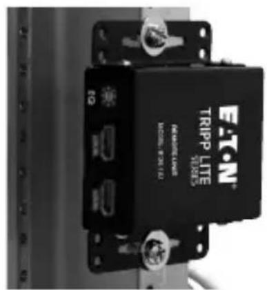
Mounting Instructions
The B116-002A, B116-002A-INT and B116-004A include mounting hardware that allows them to be mounted in a variety of ways. The following images show the different ways the included mounting brackets can be attached for different mounting methods.
Wall Mount
natural_image
Black plastic electronic device casing with ventilation slots and mounting holes (no visible text or symbols)19" Rack Mount
Pole Mount
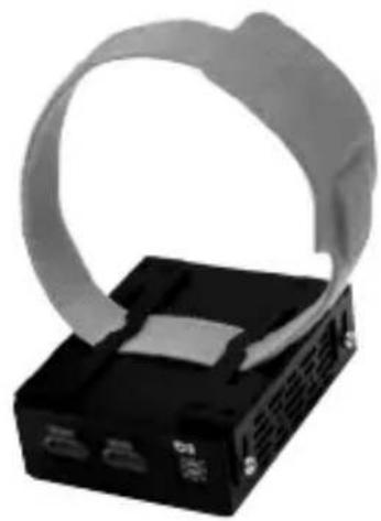
natural_image
Black electronic device with a gray cable strap and two ports, no visible text or symbols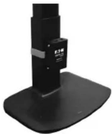
natural_image
Close-up of a black mechanical device with a base and top, no visible text or symbolsStandard Installation
In a standard installation, there is only one splitter being used to connect two (B116-002A and B116-002A-INT) or up to four (B116-004A) sets of monitors and speakers. The following rules apply to a standard installation:
• The distance between the source and the splitter must not exceed 16 ft. (5 m).
- For source video resolutions anywhere from 1600 x 1200 @ 60 Hz to 1920 x 1200 @ 60 Hz. The distance between the splitter and the connected monitor and speakers must not exceed 49 ft. (15 m). The video distance can be extended by using a B120-000 DVI extender. The B120-000 can be located up to 65 ft. (20 m) from the splitter and 16 ft. (5 m) from the connected monitor.
- For source video resolutions lower than 1600 x 1200 @ 60 Hz. The distance between the splitter and the connected monitor and speakers must not exceed 65 ft. (20 m). The video distance can be extended by using a B120-000 DVI extender. The B120-000 can be located up to 114 ft. (35 m) from the splitter and 16 ft. (5 m) from the connected monitor.
- The B116-002A, B116-002A-INT and B116-004A are designed for monitor refresh rates of 60 Hz.
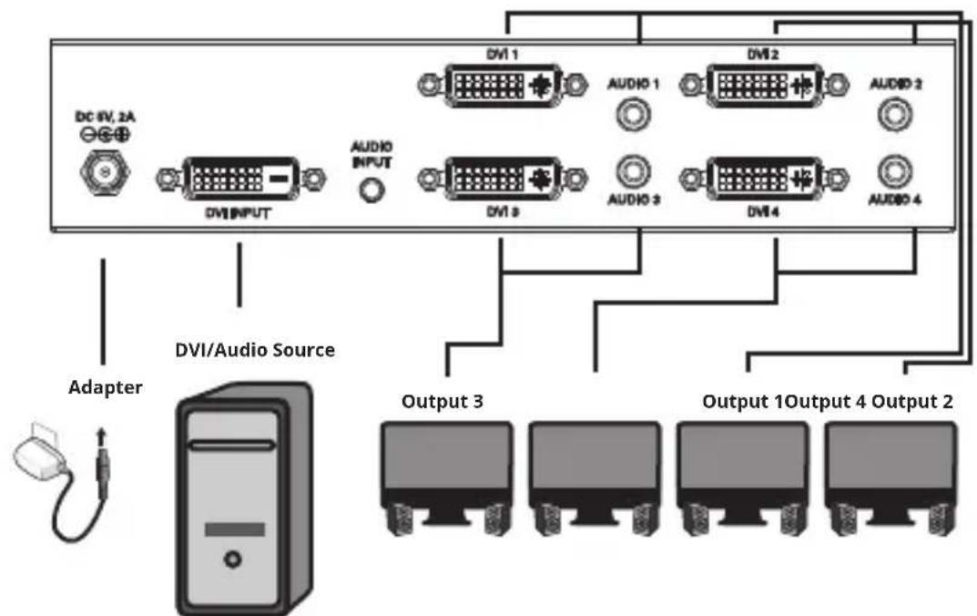
- Make sure the DVI and Audio source is powered OFF.
- Connect the DVI and Audio source to the input ports on the splitter using a DVI with 3.5 mm Audio Cable (P560-XXX-A Series), or a Single-Link DVI Cable (P561-Series) and 3.5 mm Audio cable (P312-Series).
Standard Installation
- Connect a monitor and speakers to a set of available output ports on the splitter using a DVI with 3.5 mm Audio Cable (P560-XXX-A Series) or a Single-Link DVI Cable (P561-Series) and 3.5 mm Audio cable (P312-Series).
- Repeat step 3 for each additional set of monitor and speakers you are connecting to the splitter.
- Connect the included external power supply to the splitter and plug it into a Surge Protector, Power Distribution Unit (PDU) or Uninterruptible Power Supply (UPS). The Power LED will illuminate to indicate the unit is receiving power.
- Turn on the power to all connected monitors and speakers, then turn on the power to the DVI and Audio source. The Input Port LED will illuminate to indicate it is connected to a powered-on source. The Port LEDs will illuminate to indicate the corresponding port is connected to a monitor and speakers and is receiving a signal from the source.
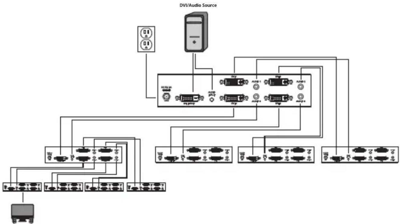
Cascade Installation
The number of connected monitors and speakers can be expanded by cascading up to three levels of splitters together. By cascading a B116-004A from each port in a three-level installation, you can connect up to 64 sets of monitors and speakers. The following rules apply to a cascade installation:
- The distance between the source and the splitter must not exceed 16 ft. (5 m).
- For source video resolutions anywhere from 1600 x 1200 @ 60 Hz to 1920 x 1200 @ 60 Hz. The distance between the first-level splitter and any last-level splitter must not exceed 65 ft. (20 m). The video distance can be extended by using a B120-000 DVI Extender in between each level of splitters. Each B120-000 Extender can be located up to 32 ft. (10 m) from a splitter and 16 ft. (5 m) from the next level splitter or connected monitor.
- For source video resolutions lower than 1600 x 1200 @ 60 Hz. The distance between the first-level splitter and any last-level splitter must not exceed 98 ft. (30 m). The video distance can be extended by using a B120-000 DVI Extender in between each level of splitters. Each B120-000 Extender can be located up to 98 ft. (30 m) from a splitter and 16 ft. (5 m) from the next-level splitter or connected monitor.
- The B116-002A, B116-002A-INT and B116-004A are designed for monitor refresh rates of 60 Hz.
Cascade Installation
flowchart
graph TD
    A["DVI/Audio Source"] --> B["Internet Port 1"]
    A --> C["Internet Port 2"]
    A --> D["Internet Port 3"]
    A --> E["Internet Port 4"]
    A --> F["Internet Port 5"]
    A --> G["Internet Port 6"]
    A --> H["Internet Port 7"]
    A --> I["Internet Port 8"]
    A --> J["Internet Port 9"]
    A --> K["Internet Port 10"]
    A --> L["Internet Port 11"]
    A --> M["Internet Port 12"]
    A --> N["Internet Port 13"]
    A --> O["Internet Port 14"]
    A --> P["Internet Port 15"]
    A --> Q["Internet Port 16"]
    A --> R["Internet Port 17"]
    A --> S["Internet Port 18"]
    A --> T["Internet Port 19"]
    A --> U["Internet Port 20"]
- Make sure the DVI and Audio source are powered OFF.
- Connect the DVI and Audio source to the input ports on the first-level splitter using a DVI with 3.5 mm Audio Cable (P560-XXX-A Series) or a Single-Link DVI Cable (P561-Series) and 3.5 mm Audio cable (P312-Series).
- Connect a set of available output ports on the first-level splitter to the input ports on a second-level splitter using a DVI with 3.5 mm Audio Cable (P560-xxx-A Series) or a Single-Link DVI Cable (P561-Series) and 3.5 mm Audio cable (P312-Series).
- Repeat step 3 for any additional splitters you wish to connect. Once you have connected a splitter to each set of ports on the first-level splitter, you can connect a third level of splitters to each set of ports on the second level. No more than three levels of splitters can be connected in a cascade installation.
- Connect a monitor and speakers to a set of available output ports using a DVI with 3.5 mm Audio Cable (P560-XXX-A Series) or a Single-Link DVI Cable (P561-Series) and 3.5 mm Audio cable (P312-Series).
- Repeat step 5 for each additional set of monitor and speakers you are connecting.
- Connect the included external power supply to the first-level splitter and plug it into a Surge Protector, Power Distribution Unit (PDU) or Uninterruptible Power Supply (UPS). The Power LED will illuminate to indicate the unit is receiving power.
Cascade Installation
- Repeat step 7 for each second-level splitter, then for each third-level splitter.
- Turn on the power to all connected monitors and speakers, then turn on the power to the DVI and Audio source. The Input Port LED will illuminate to indicate it is connected to a powered-on source. The Port LEDs will illuminate to indicate the corresponding port is connected to a monitor and speakers and is receiving a signal from the source.
Troubleshooting
If you are experiencing an issue with your splitter, trying the troubleshooting tips below may help to resolve the problem:
- Confirm that the Power LED is illuminated. If not, check if the external power supply is receiving power by plugging something else into the same power source. If it is receiving power, make sure the power supply is securely connected to the splitter. If the LED is still not illuminated, use a voltmeter to ensure the power source is providing enough power for the external power supply.
- Make sure that the cables you are using are functioning properly by connecting them directly between the source and display/speakers. Test all cables in the installation to make sure they are functioning properly.
- If the cables you are using are functioning properly, test each port on the splitter to make sure it is working. Using the cables you just tested, connect the source to the splitter, and then a set of output ports to a monitor and speakers. Test each port to make sure it is functioning properly.
Warranty
1-Year Limited Warranty
We warrant our products to be free from defects in materials and workmanship for a period of one (1) year from the date of initial purchase. Our obligation under this warranty is limited to repairing or replacing (at its sole option) any such defective products. Visit Tripplite.Eaton.com/support/product-returns before sending any equipment back for repair. This warranty does not apply to equipment which has been damaged by accident, negligence or misapplication or has been altered or modified in any way.
EXCEPT AS PROVIDED HEREIN, WE MAKE NO WARRANTIES, EXPRESS OR IMPLIED, INCLUDING WARRANTIES OF MERCHANTABILITY AND FITNESS FOR A PARTICULAR PURPOSE. Some states do not permit limitation or exclusion of implied warranties; therefore, the aforesaid limitation(s) or exclusion(s) may not apply to the purchaser.
EXCEPT AS PROVIDED ABOVE, IN NO EVENT WILL WE BE LIABLE FOR DIRECT, INDIRECT, SPECIAL, INCIDENTAL OR CONSEQUENTIAL DAMAGES ARISING OUT OF THE USE OF THIS PRODUCT, EVEN IF ADVISED OF THE POSSIBILITY OF SUCH DAMAGE. Specifically, we are not liable for any costs, such as lost profits or revenue, loss of equipment, loss of use of equipment, loss of software, loss of data, costs of substitutes, claims by third parties, or otherwise.
Warranty
WARNING!
Use of this equipment in life support applications where failure of this equipment can reasonably be expected to cause the failure of the life support equipment or to significantly affect its safety or effectiveness is not recommended.
FCC Notice, Class B
This device complies with part 15 of the FCC Rules. Operation is subject to the following two conditions: (1) This device may not cause harmful interference, and (2) this device must accept any interference received, including interference that may cause undesired operation.
Note: This equipment has been tested and found to comply with the limits for a Class B digital device, pursuant to part 15 of the FCC Rules. These limits are designed to provide reasonable protection against harmful interference in a residential installation. This equipment generates, uses and can radiate radio frequency energy and, if not installed and used in accordance with the instructions, may cause harmful interference to radio communications. However, there is no guarantee that interference will not occur in a particular installation. If this equipment does cause harmful interference to radio or television reception, which can be determined by turning the equipment off and on, the user is encouraged to try to correct the interference by one or more of the following measures:
- Reorient or relocate the receiving antenna.
- Increase the separation between the equipment and receiver.
- Connect the equipment into an outlet on a circuit different from that to which the receiver is connected.
- Consult the dealer or an experienced radio/TV technician for help.
Any changes or modifications to this equipment not expressly approved by Eaton could void the user's authority to operate this equipment.
WEEE Compliance Information for Customers and Recyclers (European Union)
Under the Waste Electrical and Electronic Equipment (WEEE) Directive and implementing regulations, when customers buy new electrical and electronic equipment from Eaton, they are entitled to:
- Send old equipment for recycling on a one-for-one, like-for-like basis (this varies depending on the country)
- Send the new equipment back for recycling when this ultimately becomes waste
Eaton has a policy of continuous improvement. Specifications are subject to change without notice. Photos and illustrations may differ slightly from actual products.

Powering Business Worldwide
Eaton
1000 Eaton Boulevard
Cleveland, OH 44122
United States
Eaton.com
© 2024 Eaton
All Rights Reserved
Publication No. 23-10-224 /
93-38AD_RevC
February 2024

9338AD
Eaton is a registered trademark.
All trademarks are property of their respective owners.
Powering Business Worldwide
Eaton
1000 Eaton Boulevard
Cleveland, OH 44122
Estados Unidos
Eaton.com
© 2024 Eaton
Installation standard
Installation standard
Powering Business Worldwide
Eaton
1000 Eaton Boulevard
Cleveland, OH 44122
États-Unis
Eaton.com
© 2024 Eaton
Powering Business Worldwide
Eaton
1000 Eaton Boulevard
Cleveland, OH 44122
Vereinigte Staaten
Eaton.com
© 2024 Eaton
natural_image
Black plastic electronic device casing with ventilation slots and mounting holes (no visible text or symbols)natural_image
Black electronic device with a white strap and two ports, no visible text or symbols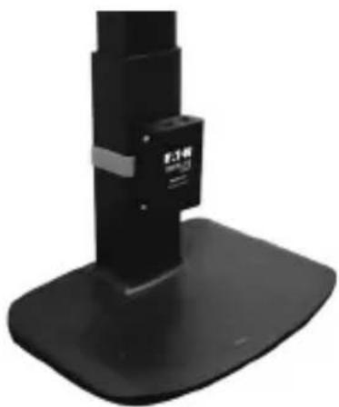
natural_image
Close-up of a black mechanical device with a base and top, no visible text or symbolsPowering Business Worldwide
Eaton
1000 Eaton Boulevard
Cleveland, OH 44122
Stati Uniti
Eaton.com
© 2024 Eaton
- 1080p DVI Splitter with Audio and Signal Booster
- Package Contents
- Product Features
- Optional Accessories
- Mounting Instructions
- Standard Installation
- Cascade Installation
- Troubleshooting
- Warranty
- 1-Year Limited Warranty
- WARNING!
- FCC Notice, Class B
- WEEE Compliance Information for Customers and Recyclers (European Union)
- Installation standard
Brand : Tripp Lite
Model : B116002AINT
Category : Distributor