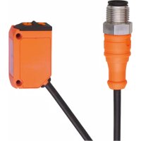
O6H205 - Motion detector IFM - Free user manual and instructions
Find the device manual for free O6H205 IFM in PDF.


User questions about O6H205 IFM
0 question about this device. Answer the ones you know or ask your own.
Ask a new question about this device
Download the instructions for your Motion detector in PDF format for free! Find your manual O6H205 - IFM and take your electronic device back in hand. On this page are published all the documents necessary for the use of your device. O6H205 by IFM.
USER MANUAL O6H205 IFM
Operating instructions
Diffuse reflection sensor with background suppression
O6H20x
Contents
1 Preliminary note.... 3
1.1 Symbols used.... 3
2 Safety instructions 4
3 Transport, handling and storage 5
4 Intended use 6
5 Installation.... 7
6 Operating and display elements.... 8
6.1 Stability indication 8
7 Electrical connection 9
7.1 PNP 9
7.2 NPN 9
8 Settings.... 10
8.1 Setting the output function.... 10
8.2 Setting the range.... 10
9 Operation.... 11
10 Maintenance, repair and disposal 12
1 Preliminary note
You will find instructions, technical data, approvals and further information using the QR code on the unit / packaging or at documentation.ifm.com.
1.1 Symbols used
Requirement
Instruction
Reaction, result
bold Designation of keys, buttons or indications
→ Cross-reference without link
→ Cross-reference with link


Important note
Non-compliance may result in malfunction or interference
Information
Supplementary note
2 Safety instructions
- The unit described is a subcomponent for integration into a system.
- The system architect is responsible for the safety of the system.
-
The system architect undertakes to perform a risk assessment and to create documentation in accordance with legal and normative requirements to be provided to the operator and user of the system. This documentation must contain all necessary information and safety instructions for the operator, the user and, if applicable, for any service personnel authorised by the architect of the system.
-
Read this document before setting up the product and keep it during the entire service life.
- The product must be suitable for the corresponding applications and environmental conditions without any restrictions.
- Only use the product for its intended purpose (→ Intended use).
- If the operating instructions or the technical data are not adhered to, personal injury and/or damage to property may occur.
- The manufacturer assumes no liability or warranty for any consequences caused by tampering with the product or incorrect use by the operator.
- Installation, electrical connection, set-up, operation and maintenance of the product must be carried out by qualified personnel authorised by the machine operator.
- Protect units and cables against damage.
3 Transport, handling and storage
▶ Store the device in its original packaging.
▶ When the device is to be stored again, use the original packaging.
▶ Otherwise, provide unused connections with either a mating connector or a protective cap and pack the device in suitable packaging.
▶ Observe the permissible ambient conditions for the device during storage (→ Technical data).
4 Intended use
The diffuse reflection sensor detects objects and materials without contact and indicates their presence by a switching signal.
5 Installation


▶ Align the diffuse reflection sensor to the object to be detected.
▶ Secure it to a bracket.

The objects to be detected should move transversely to the lens of the sensor.
▶ In case of other directions of movement it should be tested before whether safe switching is guaranteed

6 Operating and display elements

1: LED yellow - switching output active
2: Setting potentiometer "sensitivity"
3: LED green - operation, stability indication
4: Selector "output function"
6.1 Stability indication
▷ The green LED is lit when the supply voltage is applied and there is sufficient excess gain. Under these conditions the sensor receives a stable signal.
| Stable signal | Switch point | Stable signal | ||
 | ||||
| Light-on mode | ||||
| LED green | On | Off | Off | On |
| LED yellow | On | On | Off | Off |
| Dark-on mode | ||||
| LED green | On | Off | Off | On |
| LED yellow | Off | Off | On | On |
7 Electrical connection

The unit must be connected by a qualified electrician.
Observe the national and international regulations for the installation of electrical equipment.
Voltage supply according to SELV, PELV.
▶ Disconnect power.
▶ Connect the unit as follows:
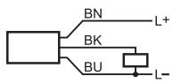
7.1 PNP
| M12 pigtail plug | Cable * | |
 |  |  |
| M8 connector, 3 poles | M8 connector, 4 poles | ||
 |  |  | 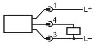 |
* Core colours: BN = brown, BU = blue, BK = black
7.2 NPN
| M12 pigtail plug | Cable * | |
 |  |  |
| M8 connector, 3 poles | M8 connector, 4 poles | ||
 | 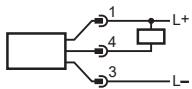 |  |  |
* Core colours: BN = brown, BU = blue, BK = black
8 Settings
8.1 Setting the output function


▶ Setting D: Dark-on mode
▶ Setting L: Light-on mode
8.2 Setting the range


▶ Increase the range: Turn the setting potentiometer clockwise.
▶ Reduce the range: Turn the setting potentiometer anticlockwise.

Objects that are beyond the set switch point are suppressed.
9 Operation
▶ Check whether the unit operates correctly.
The green LED is lit when the supply voltage is applied and there is sufficient excess gain.
▷ Setting the dark-on mode: The output is switched / the yellow LED is on when an object is detected.
▷ Setting the light-on mode: The output is switched / the yellow LED is on when no object is detected.
10 Maintenance, repair and disposal
▶ Keep the lenses of the sensor free from soiling.
▶ For cleaning do not use any solvents or cleaning agents which could damage the plastic parts.
▶ After use dispose of the unit in an environmentally friendly way in accordance with the applicable national regulations.
Faulty sensors must only be repaired by the manufacturer.
- 1 PRELIMINARY NOTE
- 1.1 SYMBOLS USED
- 2 SAFETY INSTRUCTIONS
- 3 TRANSPORT, HANDLING AND STORAGE
- 4 INTENDED USE
- 5 INSTALLATION
- 6 OPERATING AND DISPLAY ELEMENTS
- 6.1 STABILITY INDICATION
- 7 ELECTRICAL CONNECTION
- 7.1 PNP
- 7.2 NPN
- 8 SETTINGS
- 8.1 SETTING THE OUTPUT FUNCTION
- 8.2 SETTING THE RANGE
- 9 OPERATION
- 10 MAINTENANCE, REPAIR AND DISPOSAL
Brand : IFM
Model : O6H205
Category : Motion detector