OM5001 - Motion detector IFM - Free user manual and instructions
Find the device manual for free OM5001 IFM in PDF.
| Product type | Motion detector (photoelectric barrier) |
| Brand | IFM |
| Model | OM5001 |
| Range | 50 m |
| Detection principle | Photoelectric barrier with transmitter (OMS...) and receiver (OME...) |
| Supply voltage | 10–30 V DC |
| Power consumption | < 1 W |
| Electrical connection | 3 wires according to label |
| LED indicators (receiver) | Green (power), Red (reception), Yellow (output) |
| Adjustments | Sensitivity potentiometer, mode selector (NO/NC) |
| Test input | Yes (only for DC cells) |
| Protection rating | IP67 |
| Operating temperature | -25 to +80 °C |
| Housing material | Plastic |
| Mounting | Mounting holes or M30 x 1.5 thread |
| Dimensions (approximate) | 30 mm diameter x 80 mm length |
| Weight (approximate) | 100 g |
| Cleaning | Do not use solvents; clean with a soft cloth |
| Safety | Disconnect power before any connection |
| Spare parts and repairability | Device not repairable, replacement advised |
Frequently Asked Questions - OM5001 IFM
User questions about OM5001 IFM
0 question about this device. Answer the ones you know or ask your own.
Ask a new question about this device
Download the instructions for your Motion detector in PDF format for free! Find your manual OM5001 - IFM and take your electronic device back in hand. On this page are published all the documents necessary for the use of your device. OM5001 by IFM.
USER MANUAL OM5001 IFM
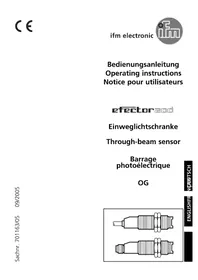
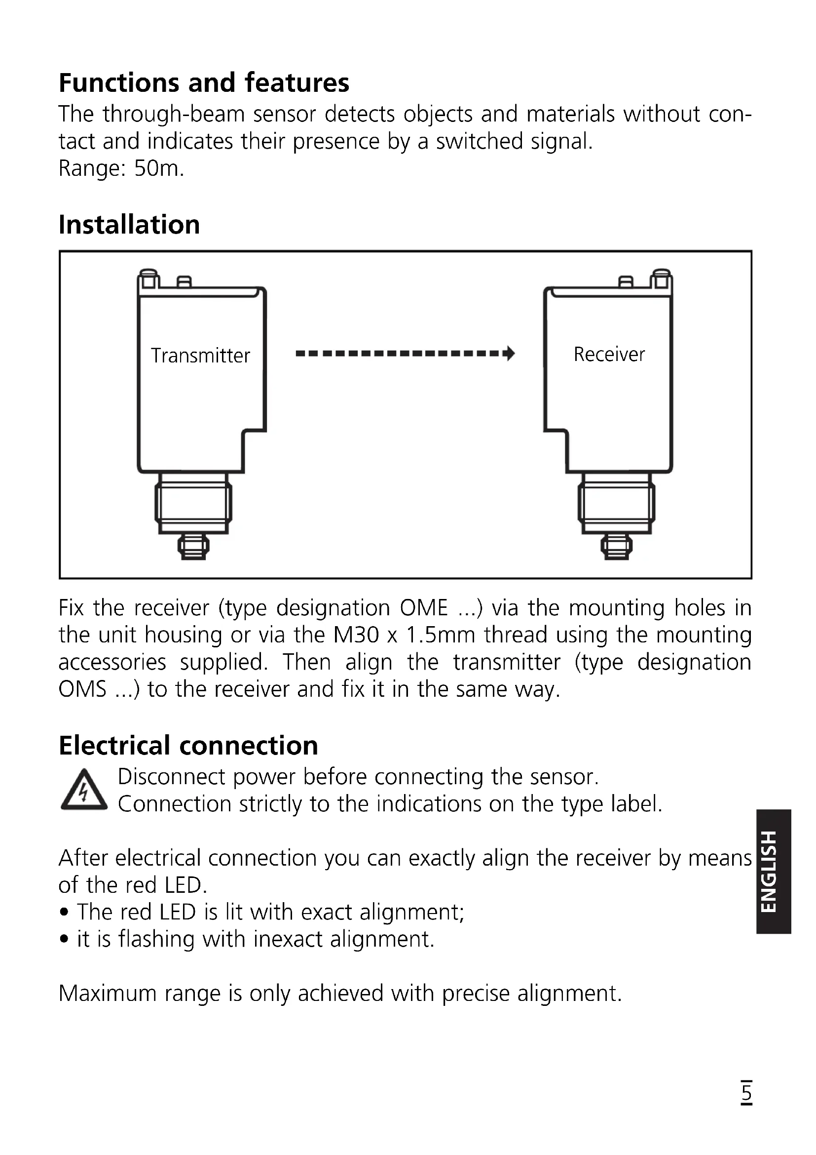
Through-beam sensor OM
Functions and features
The through-beam sensor detects objects and materials without contact and indicates their presence by a switched signal.
Range: 50m.
Installation
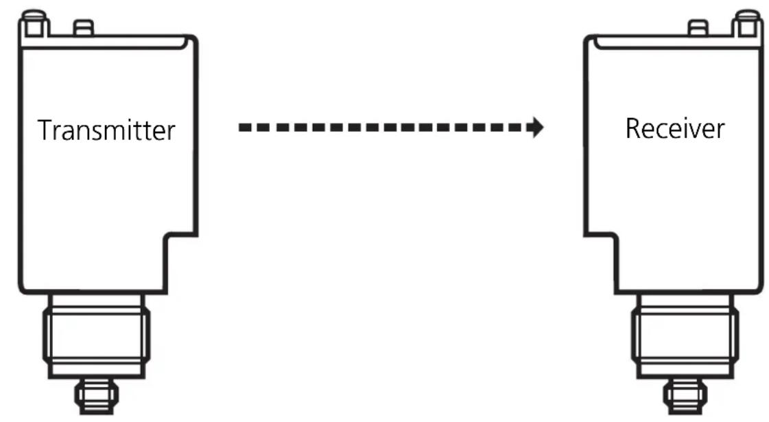
Fix the receiver (type designation OME ...) via the mounting holes in the unit housing or via the M30 x 1.5mm thread using the mounting accessories supplied. Then align the transmitter (type designation OMS ...) to the receiver and fix it in the same way.
Electrical connection
Disconnect power before connecting the sensor.
Connection strictly to the indications on the type label.
After electrical connection you can exactly align the receiver by means of the red LED.
- The red LED is lit with exact alignment;
- it is flashing with inexact alignment.
Maximum range is only achieved with precise alignment.
Sensitivity setting
Through-beam sensors are usually operated in the dark-on mode. In most applications maximum sensitivity can be used for operation. The settings described below are only necessary if partly transparent or small objects are to be detected.
- Set the sensitivity to its maximum by turning the "Range" potentiometer " of the receiver counter-clockwise until you hear a click.
- Place the object to be detected between the transmitter and the receiver.
- Turn the potentiometer for the sensitivity setting counter-clockwise until the yellow LED (output) is just lit.
- Remove the object to be detected.
- Turn the potentiometer for the sensitivity setting counter-clockwise until the yellow LED (output) is just lit and count the number of revolutions.
- Turn the potentiometer for the sensitivity setting back clockwise by half of the revolutions counted before.
- For selecting the light-on or dark-on mode, set the slide switch to the requested operating mode.
Controls and indicators (Receiver)
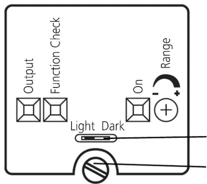
Function display
Output Yellow LED
Function Check Red LED
On Green LED
Range
Potentiometer for sensitivity setting Slide switch for the light-on or dark-on operating modes
For setting loosen the screw and open the housing cover
Test input of the transmitter (only for DC units)
By activating the test input (test at L-) the transmitter is deactivated. When no object is in the light beam between transmitter and receiver the LEDs indicating the reception of light must go off and the switching state of the output must change.
Operation
Only open the cover to make adjustments. Close it after the adjustment has been made in order to maintain the protection IP67.
Check whether the unit functions properly.
-
Light-on mode - the output is switched when the object is not present. The yellow LED (only receiver) is lit.
-
Dark-on mode – the output is switched when the object is present. The yellow LED (only receiver) is lit.
-
The green LED is lit when the sensor is ready for operation.
-
The red LED (only receiver) is lit when the light is received (= no object between transmitter and receiver);
-
it flashes when reception is impaired (e.g. due to soiling of the lenses or maladjustment). If an unsafe signal is present for two seconds, the function check output switches and remains switched until a safe signal is received.
Maintenance
Keep the lens of the sensor free from soiling. For cleaning do not use any solvents or cleaning agents which could damage the plastic lenses.
LED " Function Check " rouge
Sortie contrôle
LED " On " verte
Fonctionnement
Range