
Power HUB Module - Electrical module GYS - Free user manual and instructions
Find the device manual for free Power HUB Module GYS in PDF.
User questions about Power HUB Module GYS
0 question about this device. Answer the ones you know or ask your own.
Ask a new question about this device
Download the instructions for your Electrical module in PDF format for free! Find your manual Power HUB Module - GYS and take your electronic device back in hand. On this page are published all the documents necessary for the use of your device. Power HUB Module by GYS.
USER MANUAL Power HUB Module GYS
natural_image
Technical line drawing of a rectangular electronic enclosure with multiple hexagonal bolt holes and mounting holes (no text or symbols)POWER HUB
MODULE
FR 2-7 / 38-40
EN 2 / 8-12 / 38-40
DE 2 / 13-17 / 38-40
ES 2 / 18-22 / 38-40
RU 2 / 23-27 / 38-40
NL 2 / 28-32 / 38-40
IT 2 / 33-37 / 38-40
FIG I
text_image
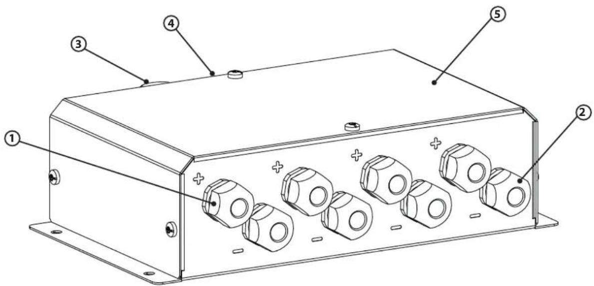
Technical diagram of an electronic device with numbered components and labeled parts| 1 | Presse-étoupe d'entrée + / Input + cable gland / Anschluss Ladegerät +Pol / Racor de estopas de entrada para cables + / Кабельный ввод-сальник + / Stopbuspakking ingang +/ Pressacavo d'entrata + / |
| 2 | Presse-étoupe d'entrée - / Input - cable gland / Anschluss Ladegerät -Pol / Racor de estopas de entrada para cables - / Кабельный ввод-сальник - / Stopbuspakking ingang - / Pressacavo d'entrata - |
| 3 | Presse-étoupe de sortie + / Output + cable gland / Anschluss Batterie +Pol / Racor de estopas de salida para cables + / Выходной сальник + / Stopbuspakking uitgang + / Pressacavo d'uscita + |
| 4 | Presse-étoupe de sortie - / Output - cable gland / Anschluss Batterie -Pol / Racor de estopas de salida para cables - / Выходной сальник - / Stopbuspakking uitgang - / Pressacavo d'uscita - |
| 5 Capot / Hood / Gehäuse / Cubierta / Крышка / Behuizing / Coperchio | |
LIVRÉ AVEC / SUPPLIED WITH / LIEFERUMFANG / INCLUYE / В НАБОРЕ ПОСТАВЛЯЮТСЯ / GELEVERD MET / FORNITO CON
| 10 vis (embout T30) / 10 screws (tip T30) / 10 Schrauben (T30) / 10 tornillos (punta T30) / 10 деталей крепления (размер T25) / 10 schroeven (T30) / 10 viti (ghiera T30) | |
| Cosses / Lugs / Kabelschuhe / Dedales / Клемы / Aansluitingen / Capicorda :- 8 × 10 mm^2 - 8 × 16 mm^2 - 10 × 25 mm^2 - 2 × 35 mm^2 - 2 × 50 mm^2 - 2 × 70 mm^2 | 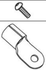 |
| 3 gaines thermorétractables / 3 heat-shrinkable sleeves / 3 Schrumpfschläuche / 3 tubos termorretráctiles / 3 термоусадочных трубки / 3 krimpkousen / 3 guaine termoretratibili :- 2 × 100 mm (sortie / outlet / ausgang / salida / выход / uitgang / uscita )- 1 × 200 mm ( 8 × 25 mm - entrée / inlet / eingang / entrada / вход / ingang / entrata ) | 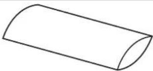 |
INSTRUCTIONS DE SÉCURITÉ

 | This manual includes guidelines on the operation of your device and the precautions to follow for your own safety.Ensure it is read carefully before first use and keep it handy for future reference. The safety instructions must be followed. In case of improper or unsafe use, the manufacturer cannot be held responsible |
 | Device suitable for indoor use only. Do not expose to rain or excessive moisture. |
| Do not place the device near a fire or subject it to heat or to longterm temperatures exceeding 50°C | |
 | Maintenance:Under no circumstances should solvents or other aggressive cleaning agents be used.Clean the device's surfaces with a soft, dry cloth. |
 | Regulations:The device complies with European Directive.The certificate of compliance is available on our website.Equipment in compliance with British requirements. The British Declaration of Conformity is available on our website (see home page). |
 | |
 | Equipment in conformity with Moroccan standards.The declaration C_ (CMIM) of conformity is available on our website (see cover page). |
 | Disposal:This product should be disposed of at an appropriate recycling facility. Do not dispose of in domestic waste. |
GENERAL DESCRIPTION
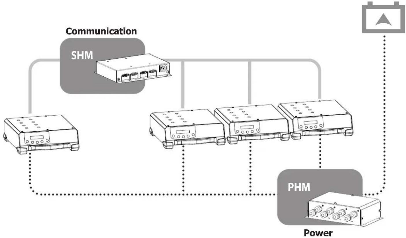
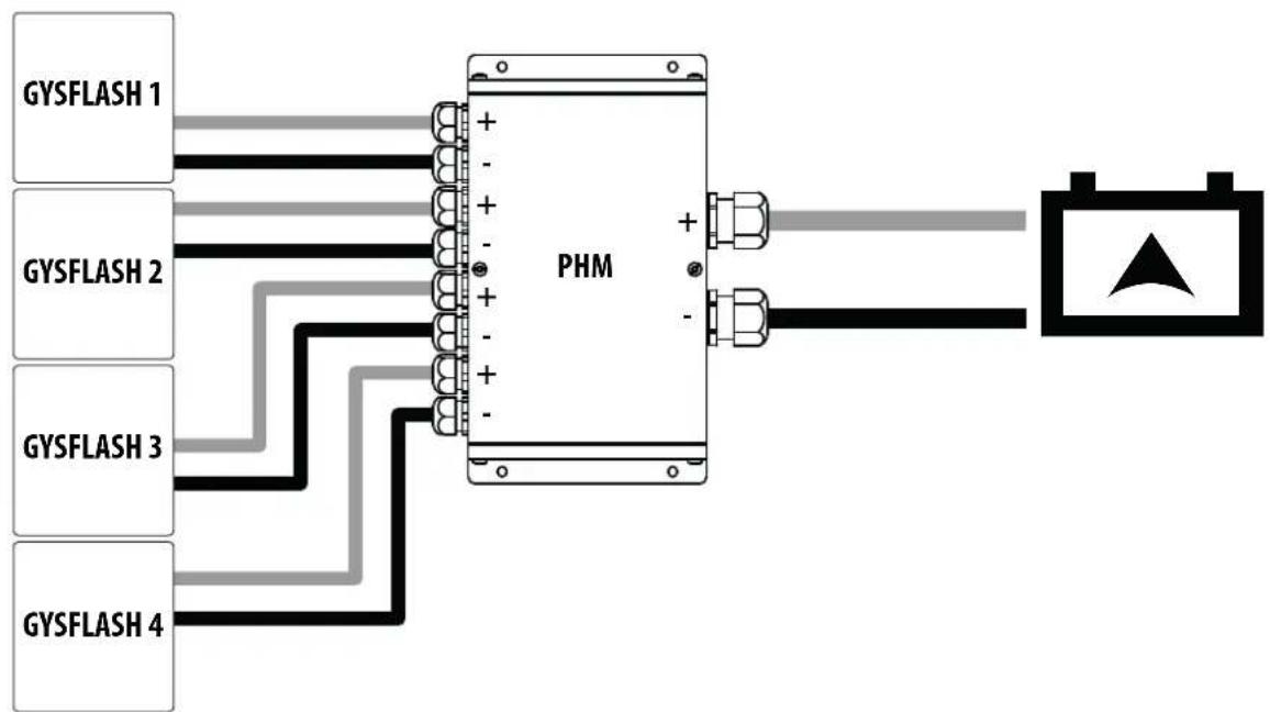
The Power Hub Module (PHM) is an accessory that allows GYSFLASH to be coupled in parallel (maximum 4) in order to increase their power to recharge a large capacity battery.

The connected GYSFLASH must be identical.

The PHM must be associated with a Smart Hub Module–SHM (ref. 025981) that establishes communication between all connected GYSFLASH.
flowchart
graph TD
    A["Communication"] --> B["SHM"]
    B --> C["Power"]
    C --> D["PHM"]
    D --> E["Output"]
    style A fill:#f9f,stroke:#333
    style B fill:#ccf,stroke:#333
    style C fill:#cfc,stroke:#333
    style D fill:#fcc,stroke:#333
    style E fill:#ffc,stroke:#333
flowchart
graph LR
    GYSFLASH1[" GYSFLASH 1 "] --> PHM[" PHM "]
    GYSFLASH2[" GYSFLASH 2 "] --> PHM
    GYSFLASH3[" GYSFLASH 3 "] --> PHM
    GYSFLASH4[" GYSFLASH 4 "] --> PHM
    PHM -->|+ -| Battery[" Battery "]
    PHM -->|- | Battery
    Battery --> A[" Triangle Symbol"]
PREPARATION

Before wiring the product, make sure that all chargers are switched off and that no batteries are connected (risk of short circuit).
| 1 Unscrew the cover (5) of the PHM (6 screws). | 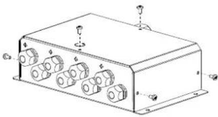 | |
| Connection inlet PHM | ||
| 2 | Remove the clamps from the power cables of the GYSFLASH chargers. | 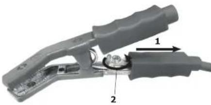 |
| If the charging cables are too long (2.5 or 5 m depending on the GYSFLASH):- Cut the cables to the desired length.- choose the appropriate lug (10, 16 or 25 mm^2 depending on the GYSFLASH cable(s)).- crimp with appropriate pliers.- Shrink tubing to the wall (use 25 mm of the 200 mm tubing heat-shrinkable supplied).⚠ The length of the cable must not be less than 1 m. | ||
| 3 | Pass the red cable through an input cable gland + (1) of the housing.And the black cable in an inlet cable gland - (2) of the housing. | 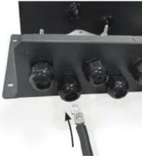 |
| 4 | Screw the cables to the corresponding plate with the screws provided in the bag (red cable to Cu plate + above / black cable to Cu plate - below).⚠ Tighten the screws well (5 Nm). | 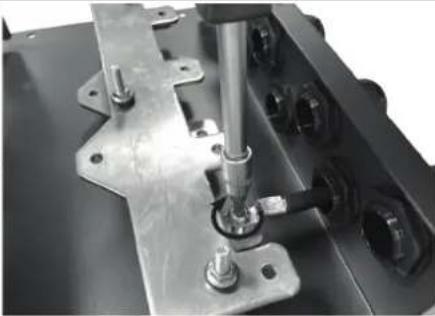 |
| 5 Tighten the cable glands used. | 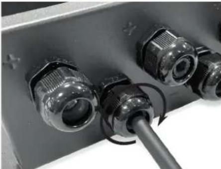 | |
| PHM output connection | |||||||||||||||||||
| 6 | Depending on the desired charging current:1. choose a cable (not supplied) with the appropriate cross-section (see recommendations table below).2. Choose the corresponding cable lug (25, 35, 50, 70 mm2 supplied).3. crimp with an appropriate crimping tool. | ||||||||||||||||||
| Recommendations on the maximum length of cables in metres, depending on their cross-section and current intensity. | |||||||||||||||||||
| I max (A) | |||||||||||||||||||
| 100 120 140 160 180 200 220 240 250 260 280 300 320 340 360 380 400 | |||||||||||||||||||
| Cross-section(mm2) | 25 | 15 | 12 | 11 | 9,2 | 8,2 | 7,4 | - | - | - | - | - | - | - | - | - | - | - | |
| 35 | 21 17 | 15 13 11 | 10 9,4 8,6 8,2- | ||||||||||||||||
| 50 | 29 25 | 21 18 16 | 15 13 12 | 12 11 | 11 9,8 9,2- | ||||||||||||||
| 70 | 41 34 | 29 26 23 | 21 19 17 | 16 16 | 15 14 13 | 12 11 11 | 10 | ||||||||||||
| Values given for the use of fully copper-plated cables. | |||||||||||||||||||
| 7 | Shrink the heat-shrinkable tubing provided. |  | |||||||||||||||||
| 8 | Pass the red cable through an input cable gland + (1) of the housing.And the black cable in an inlet cable gland - (2) of the housing. |  | |||||||||||||||||
| 9 | Screw the cables with the screws provided in the bag (red wire at the top / black wire at the bottom)△ Tighten the screws well (5 Nm). |  | |||||||||||||||||
| 10 | Tighten the cable gland. |  | |||||||||||||||||
| 11 | Replace the product cover. |  | |||||||||||||||||
FIXING
It is possible to fix the PHM to the wall via its 4 fixing holes (screws not supplied).
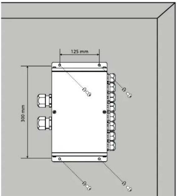
text_image
125 mm 300 mm ø ø ø ø øWARRANTY
The warranty covers faulty workmanship for 2 years from the date of purchase (parts and labour).
The warranty does not cover:
- Transit damage.
- Normal wear of parts (eg. : cables, clamps, etc..).
- Damages due to misuse (power supply error, dropping of equipment, disassembling).
- Environment related failures (pollution, rust, dust).
In case of failure, return the unit to your distributor together with:
- The proof of purchase (receipt etc ...)
- A description of the fault reported
