
Array - Embroidery machine BABY LOCK - Free user manual and instructions
Find the device manual for free Array BABY LOCK in PDF.
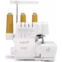
| Product Type | Multi-needle embroidery machine |
| Brand | Baby Lock |
| Model | Array |
| Category | Embroidery machine |
| Dimensions (approx.) | 80 cm (W) x 60 cm (D) x 70 cm (H) |
| Weight (approx.) | 40 kg |
| Power supply | 120 V, 60 Hz, 120 W |
| Maximum embroidery area | 130 mm (W) x 60 mm (H) with cap frame |
| Number of needles | 6 needles |
| Main functions | Embroidery on caps, garments and accessories; support height adjustment; visor protection |
| Included accessories | Cap frame, frame support, assembly device, visor protector, spacer, Allen wrench |
| Maintenance and cleaning | Regular cleaning of the carriage and support; checking of tightening screws |
| Safety | Automatic stop in case of jam; power off before changing support |
| Spare parts and repairability | Needles, bobbins, cap frame, tightening screws, springs |
| General information | Professional embroidery machine for intensive use |
Frequently Asked Questions - Array BABY LOCK
User questions about Array BABY LOCK
0 question about this device. Answer the ones you know or ask your own.
Ask a new question about this device
Download the instructions for your Embroidery machine in PDF format for free! Find your manual Array - BABY LOCK and take your electronic device back in hand. On this page are published all the documents necessary for the use of your device. Array by BABY LOCK.
USER MANUAL Array BABY LOCK
By using the cap frame, patterns can be embroidered onto caps and hats. The procedures for using the cap frame are described below.
Cap frame and its accessories
Check that the following cap frame, cap frame driver, cap frame mounting jig and the accessories are included. If any item is missing or damaged, contact your sales representative.
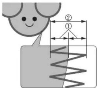
Cap frame: Upper frame/Lower frame
① Embroidering area: 130mm ()× 60mm H5-1/8 inches (W)× 2 - 3 / 8 inches (H))
② Marks indicating the center of the embroidery area
③Lock knob Used when attaching and removing the upper frame.
④ Clips Found here when the frame is purchased.Use to attach the cap to the cap frame.

- When the frame is purchased, the upper and lower frames are attached together.
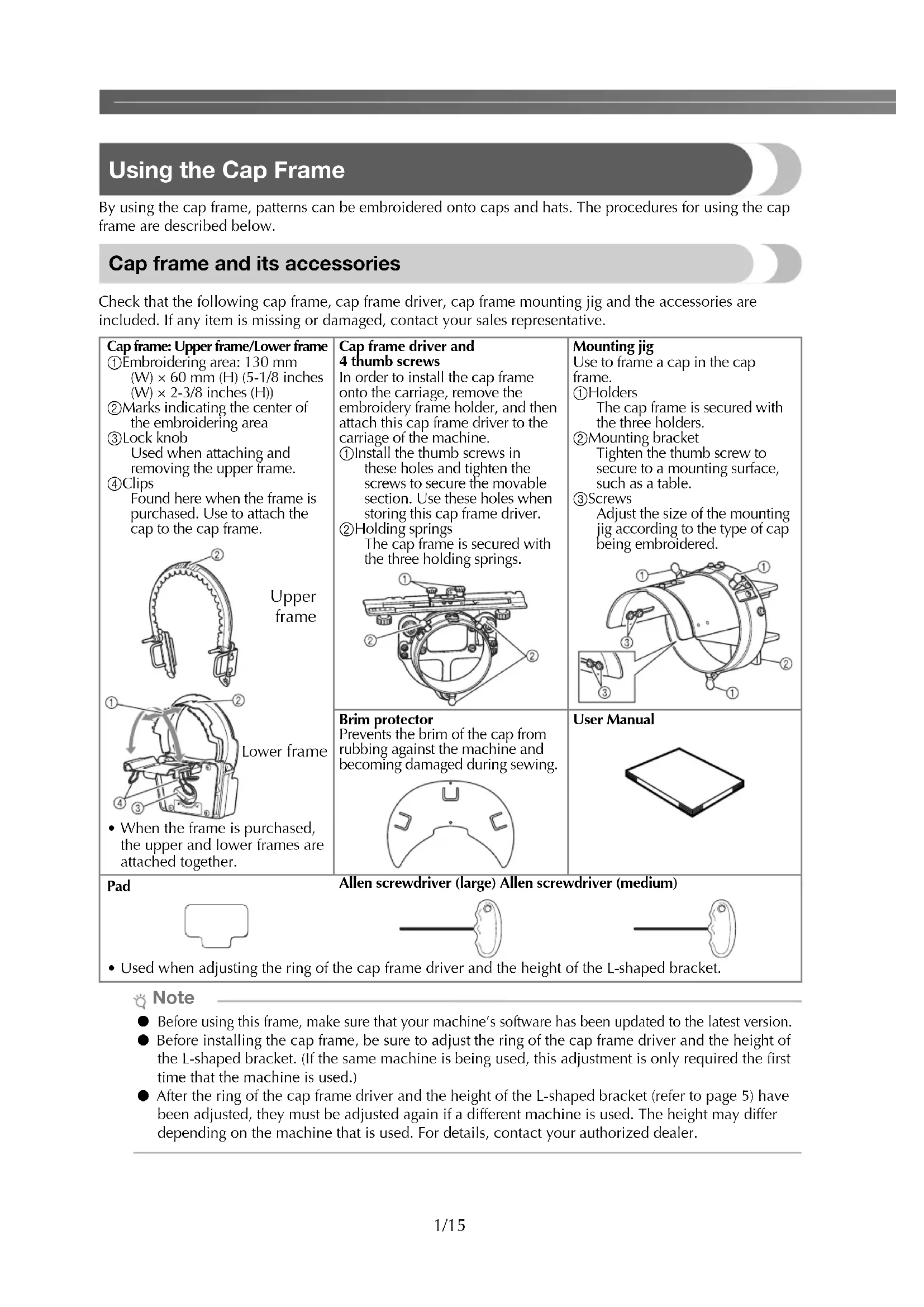
Cap frame driver and 4 thumb screws
In order to install the cap frame onto the carriage, remove the embroidery frame holder, and then attach this cap frame driver to the carriage of the machine.
① Install the thumb screws in these holes and tighten the screws to secure the movable section. Use these holes when storing this cap frame driver.
Holding springs The cap frame is secured with the three holding springs.
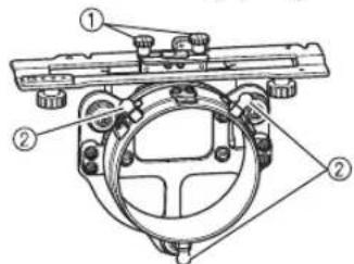
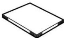
Brim protector
Prevents the brim of the cap from rubbing against the machine and becoming damaged during sewing.
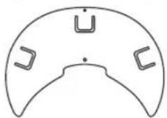
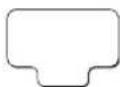
Mounting jig
Use to frame a cap in the cap frame.
① Holders
The cap frame is secured with the three holders.
② Mounting bracket
Tighten the thumb screw to secure to a mounting surface, such as a table.
③Screws
Adjust the size of the mounting jig according to the type of cap being embroidered.
User Manual
Pad
Allen screwdriver (large) Allen screwdriver (medium)
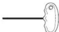
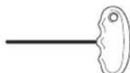
- Used when adjusting the ring of the cap frame driver and the height of the L-shaped bracket.
Note
- Before using this frame, make sure that your machine's software has been updated to the latest version.
- Before installing the cap frame, be sure to adjust the ring of the cap frame driver and the height of the L-shaped bracket. (If the same machine is being used, this adjustment is only required the first time that the machine is used.)
- After the ring of the cap frame driver and the height of the L-shaped bracket (refer to page 5) have been adjusted, they must be adjusted again if a different machine is used. The height may differ depending on the machine that is used. For details, contact your authorized dealer.
Types of caps
With this machine, we recommend that the following types of caps be embroidered.
An Otto International, Inc. cap is used here as an example.
(* The ease of framing shown in the table is as evaluated by our company.)
- Any trade names and product names of companies appearing on our products, related documents and any other materials are all trademarks or registered trademarks of those respective companies.
Standard (pro style)
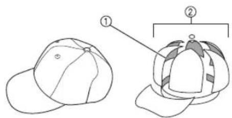
①Face: Pro style
② 6 sections
| Mesh backing at back of front panels (soft or hard*) | Constructed firm front | Unconstructed soft crown |
| Ease of framing* (hooping) | Easy (Recommended) | Fairly easy |
| Backing 1- to 2-ply 2- to 3-ply | ||
| Otto International, Inc. cap model number (Example) | OTTO27-007 | |
Low profile (low fitting)
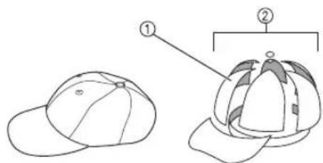
①Face: Low fitting
② 6 sections
| Mesh backing at back of front panels (soft or hard*) | Constructed firm front | Unconstructed soft crown | Constructed firm front |
| Ease of framing* (hooping) | Easy | Fairly easy | Easy |
| Backing | 1- to 2-ply | 2- to 3-ply | 1- to 2-ply |
| Otto International, Inc. cap model number (Example) | OTTO23-255 | OTTO18-202 | OTTO65-758 (for children) |
Flat visor
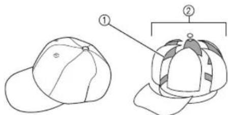
①Face: Pro style
(2)6 sections
| Mesh backing at back of front panels (soft or hard*) | Constructed firm front | Constructed firm front |
| Ease of framing* (hooping) | Easy Easy | |
| Backing 1- to 2-ply | 1- to 2-ply | |
| Otto International, Inc. cap model number (Example) | OTTO125-1038 | OTTO145-1044 (for children) |
Golf style
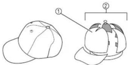
①Face: Not divided
25 sections
| Mesh backing at back of front panels (soft or hard*) | Constructed firm front |
| Ease of framing* (hooping) Fairly easy | |
| Backing 1- to 2-ply | |
| Otto International, Inc. cap model number (Example) | OTTO37-024 |

Memo
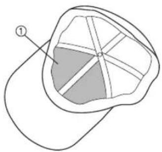
- Check if area ① is covered with mesh. (A cap with mesh is shown below.)

Note
There is no centerline that can be used as a guide for placing the cap in the cap frame. Before framing the cap, use a chalk pencil to mark the centerline.
Caps not recommended for embroidering
- Caps with a front panel that is less than 50 mm (2 inches) high (such as a sun visor)
- Caps with a brim that is longer than 80mm (3-1/16 inches)
Fabric precautions
Cap fabric recommended for embroidering
35% cotton/65% polyester
100% cotton
- 80% wool/20% nylon
15% wool/85% acrylic
Cap fabric not recommended for embroidering
Caps of the following types of fabric are very difficult to frame, may wrinkle, or may shrink.
- Polyester foam
- Stretch fabrics
- Melton wool
- 100% nylon
Suede
Preparing to use the cap frame
■ Installing the cap frame driver
Remove the embroidery frame holder from the carriage of the machine, and then install the cap frame driver. Before removing the embroidery frame holder, remove the embroidery frame.

CAUTION

Before changing any embroidery frame holder, make sure your machine is turned off.
Loosen the two thumb screws, and then remove the embroidery frame holder and thumb screws.
①Thumb screws
- The thumb screws should remain attached to the embroidery frame holder.
① Store the two thumb screws in the embroidery frame holder so they will not be lost.
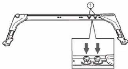
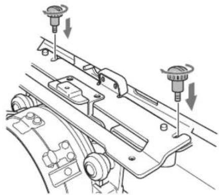
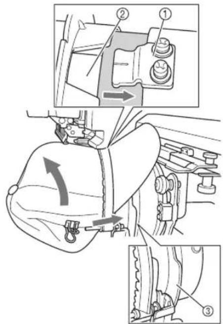
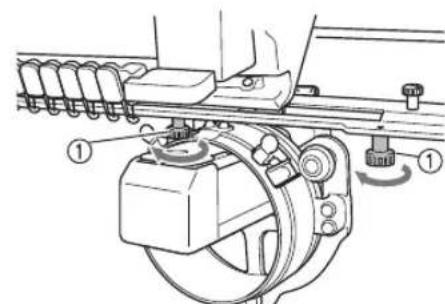
Remove the two upper thumb screws of the cap frame driver, and then loosen the two lower thumb screws.
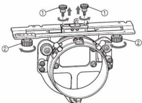
①Upper thumb screws
②Lower thumb screws
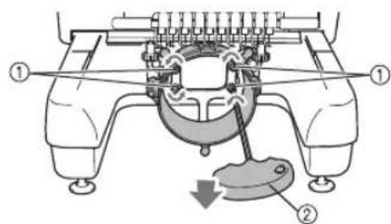
Turn on the machine, using its main power switch. After the carriage moves to its initial position, turn off the machine.
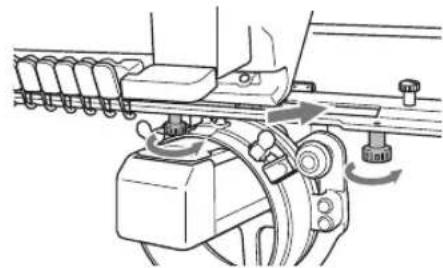
Pass the machine bed through the ring of the cap frame driver.
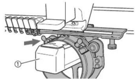
①Machine bed
Note
- Be careful that the cap frame driver does not hit any nearby parts, such as the presser foot.
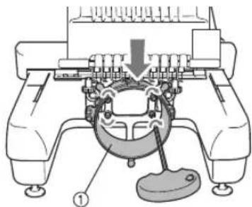
Attach the cap frame driver to the carriage as described below in steps 5 through 8.
5 Insert the two thumb screws at the bottom of the cap frame driver into the V-cuts in the carriage, and then place the mounting plate of the cap frame driver on top of the framemounting plate of the carriage.
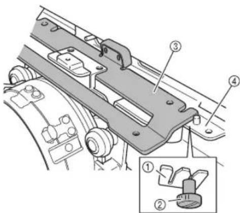
① V-cut in the carriage
②Thumb screw of the cap frame driver
③ Mounting plate of the cap frame driver
④Frame-mounting plate of the carriage
6 Insert the pins on the frame-mounting plate of the carriage into the holes in the mounting plate of the cap frame driver.
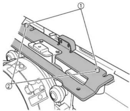
① Pins on the frame-mounting plate of the carriage
(2)Holes in the mounting plate of the cap frame driver
Install and tighten the two upper thumb screws (removed in step ②) in the outer holes of the mounting plate of the cap frame driver.
While pushing in the cap frame driver toward the machine so that it is fully inserted, tighten the two lower thumb screws to secure the cap frame driver.
This completes the installation of the cap frame driver.
Adjusting the cap frame driver
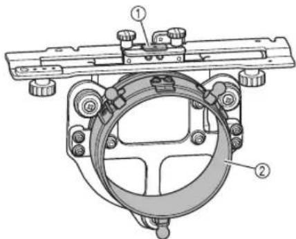
① L-shapedbracket
② Ring

Memo
- If the same machine is being used, the adjustment to the cap frame driver is only required the first time that the machine is used.

Turn on the machine, using its main power switch. After the carriage moves to its initial position, turn off the machine.

Note
- Be sure to adjust the cap frame driver with the carriage at its initial position.

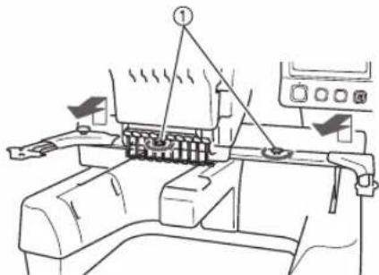
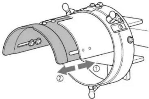
Using the Allen screwdriver (medium), loosen the two hexagonal screws one turn in the direction of the arrow.
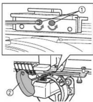
①Hexagonal screws
② Allen screwdriver (medium)

Note
- Do not loosen the screws too much.
Lower the L-shaped bracket so that it touches the machine bed, and then use the Allen screwdriver (medium) to firmly tighten the two hexagonal screws.
① L-shapedbracket
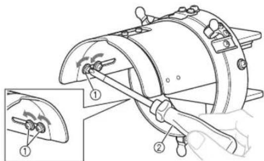
Using the Allen screwdriver (large), loosen the four hexagonal screws on the inside of the ring one turn in the direction of the arrow.
①Hexagonal screws
② Allen screwdriver (large)
When the screws are loosened, the ring can be lowered.

Note
- Do not loosen the screws too much.
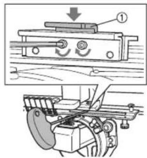
Insert the pad between the machine bed and the ring of the cap frame driver.

①Pad
②Machine bed
③ Ring of the cap frame driver

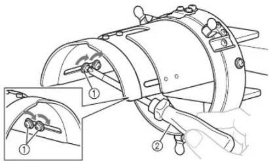
Lightly press down the ring, and then use the Allen screwdriver (large) to firmly tighten the four hexagonal screws on the inside of the ring.
① Ring

CAUTION

- Make sure that each hexagonal screw is firmly tightened. If any screw remains loose, injuries may result.

Remove the pad inserted in step ⑤.
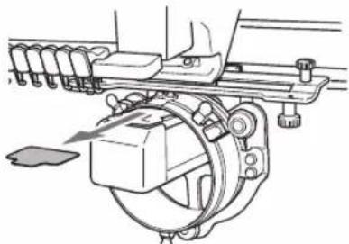
■ Installing the needle plate spacer
Attach the needle plate spacer (included with the machine) to the needle plate.
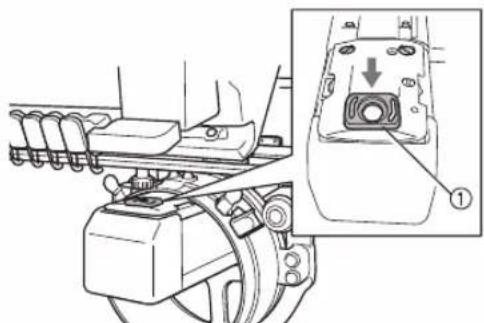
①Needle plate spacer
Preparing the mounting jig
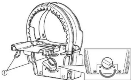
Attach the mounting jig to a stable surface, such as a desk.

Loosen the thumb screw for the mounting jig to open the mounting bracket so that it is wider than the thickness of the mounting surface.
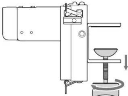
- The mounting bracket can be mounted onto a mounting surface with a thickness between 9 mm (3/8 inch) and 38 mm (1-1/2 inches).

Securely clamp the mounting bracket onto the mounting surface by tightening the thumb screw.
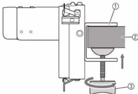
① Mounting bracket
② Mounting surface (worktable, desk, etc.)
③ Tighten the thumb screw.

Memo
- If there is a gap between the clamping pad of the thumb screw and the mounting surface, insert the included pad as shown below.
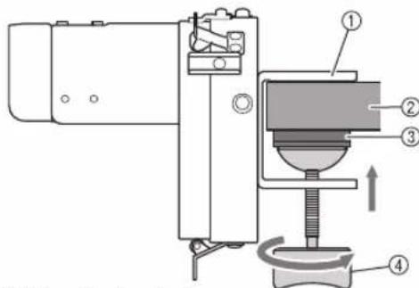
① Mounting bracket
② Mounting surface (worktable, desk, etc.)
③Pad
④Thumb screw

Check that there is no looseness.
If there is looseness, mount the mounting jig onto the mounting surface again.

Note
Make sure that the mounting bracket is securely clamped onto the mounting surface and that the thumb screw is firmly tightened.
- Do not attach the mounting jig to an unstable surface (flexible, bent or warped).
- Be careful that the mounting jig does not fall when it is removed.

Adjust the size of the mounting jig according to the type of cap being embroidered.
① Low profile (low fitting)
②Standard(pro style)

For the standard type
Using a Phillips screwdriver, loosen the four screws (two on the left and two on the right) on the inside of the mounting jig one turn.
① Screws
② Phillips screwdriver

Note
- Do not remove any of the four screws (two on the left and two on the right), otherwise they may be lost. Only turn the screws to slightly loosen them.
Pull the mounting jig toward you, and then use the Phillips screwdriver to tighten the four screws (two on the left and two on the right).
This completes the preparation of the mounting jig.
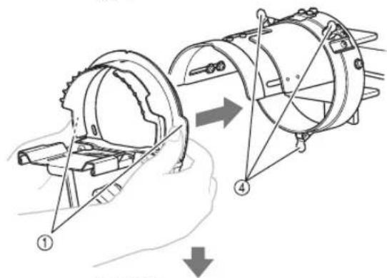
Removing the upper frame of the cap frame from the lower frame
When the cap frame is purchased, the upper and lower frames are attached together. Remove the upper frame from the lower frame.

Remove the clips attached to the lower frame, and then set the lock knob to the unlocked position.
① Clips

Grab the grips of the upper frame and remove the upper frame from the lower frame.

①Grip
Attaching the cap frame
- Attaching the lower frame of the cap frame to the mounting jig
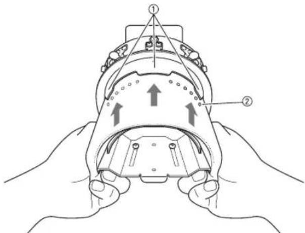
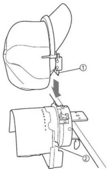
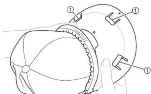
1 Attach the lower frame of the cap frame to the mounting jig.
Grab the grips on both sides of the lower frame of the cap frame and push.
When positioning the lower frame of the cap frame, align the notch in the lower frame with the guiding plate at the center of the mounting jig.
① Grips
②Guiding plate on mounting jig
③Notch in lower frame
④ Holders
The cap frame is secured with three holders.
2 Slide stabilizer under the three tabs on the lower frame of the cap frame, and then secure the stabilizer with the pins.
①Three tabs
②Pin
-
Make sure that the pins go through the stabilizer to firmly secure it.
-
Attach the cap to the cap frame
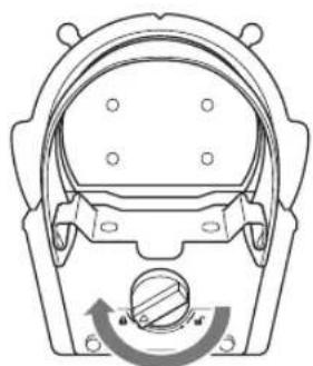
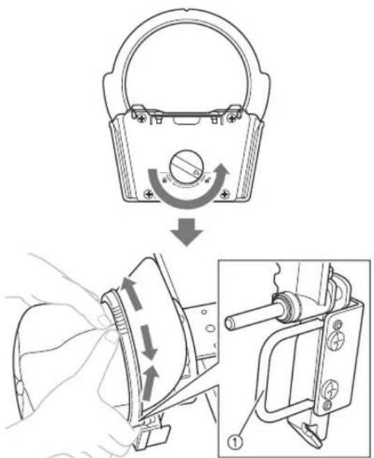
1 Set the lock knob on the lower frame to the locked position.
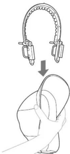
Lightly squeeze the brim of the cap and fit the upper frame onto the base of the cap brim.
- Do not force the upper frame to widen. This may damage the frame.
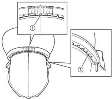
Align the centerline of the upper frame with the centerline of the cap, and then fit the teeth at the center and left and right sides of the upper frame into the base of the cap brim.
Do this while lightly squeezing the cap brim.
- Do not force the upper frame to widen. This may damage the frame.
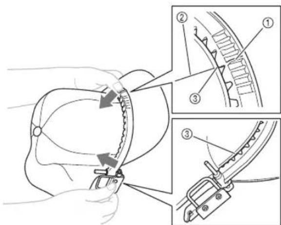
①Centerline of the upper frame
②Centerline of the cap
③Base of the cap brim

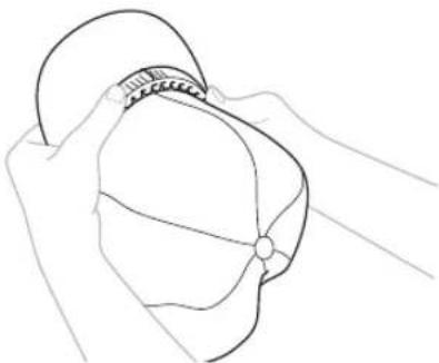
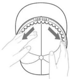
While holding the upper frame and cap brim together, fit the remainder of the upper frame onto the base of the cap brim.
Depending on the cap type, the cap brim may not perfectly align with the upper frame in areas other than the center and left and right sides.

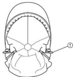
Flip out the cap's sweat guard, and then fit it between the pin and fitting on each side of the upper frame.
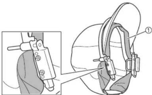
① Sweat guard

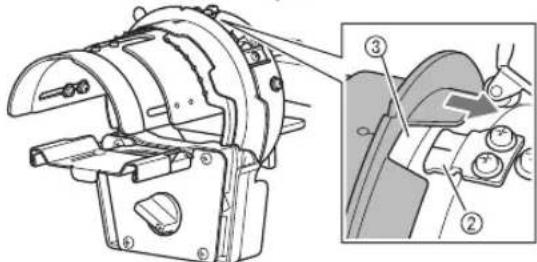
Position the upper frame from the top so that the tab on each side of the upper frame fits into the opening on each side of the lower frame.
①Tab on the upper frame
② Opening in the lower frame
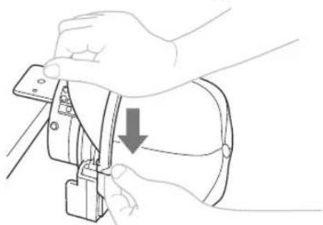
While holding the bottom of the lower frame with your fingers, push the pin on the upper frame downward with your thumb.
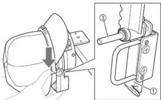
③Pin on the upper frame

Note
- If it is difficult to push the pin on the upper frame downward, push downward at the center of the upper frame with your hand to help push down the upper frame. Do this on both the left and right sides.

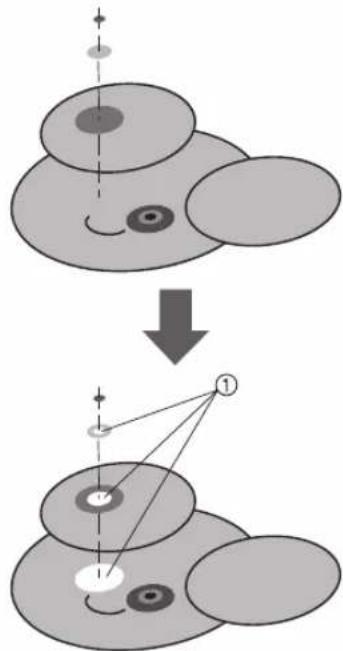
Check that the centerline of the cap is aligned with the projections and V-shaped notch at the center of the mounting jig.
Check by lightly pressing on the outside of the cap with your hand.
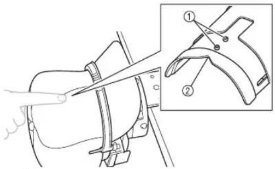
① Projections
② V-shaped notch

Memo
If the centerline of the cap is not aligned with the projections and V-shaped notch:
- Set the lock knob on the lower frame to the unlocked position.
- Grab the grips of the upper frame and pull the frame up, and then reposition it so that it is even on the left and right sides.
- Set the lock knob on the lower frame to the locked position again.
- Perform steps 6 through 7 again.
①Grip

Check that the teeth at the center and left and right sides of the upper frame are fitted into the base of the cap brim.
①Base of the cap brim

Pull the cap fabric outward from the center to remove any slack.

Use the clips to secure the cap.
①Clip
- For details on the areas to be secured with the clips, refer to step ① in "Removing the upper frame of the cap frame from the lower frame" on page 7.
- Repeat steps 9 and 10 on the other side to remove any slack and secure the fabric with the clips.
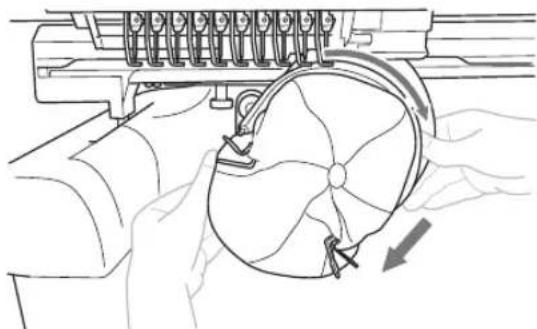
11 Remove the cap frame from the mounting jig.
Grab the grips on both sides of the cap frame and pull off the frame as shown. It may be easier to remove the frame by applying force to one grip at a time.
①Grip
- Attaching the cap frame to the embroidery machine
The cap frame driver is required in order to attach the cap frame to the embroidery machine. Before attaching the cap frame to the machine, attach the cap frame driver to the carriage.
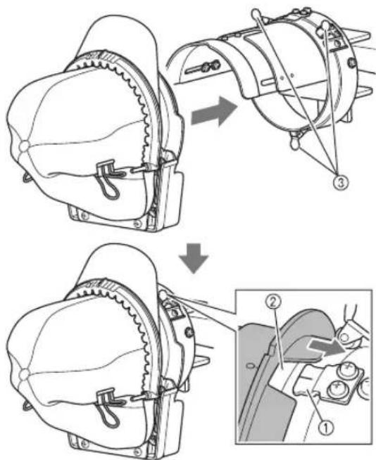
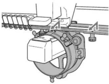
1 Attach the cap frame to the cap frame driver.
As shown, turn the embroidering area to the side when inserting the cap frame so the brim of the cap does not hit the embroidery machine.
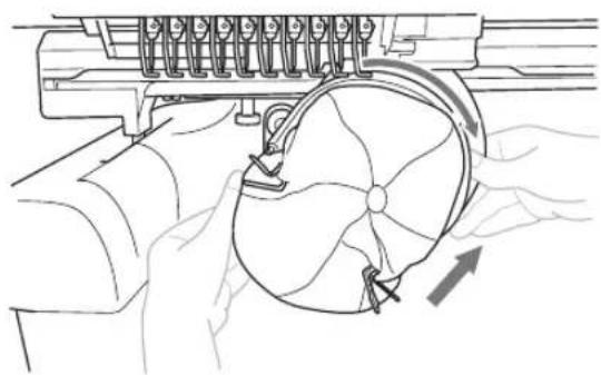
- Be careful that the cap frame does not hit any nearby parts, such as the presser foot.
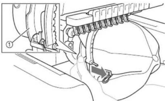
After turning the cap frame so that the.
embroidering area faces upward, align the
ring of the cap frame driver with the ring of
the cap frame. While sliding the cap frame to
the left and right, align the notch in the cap
frame with the guiding plate on the cap frame
driver, and grab the grips on both sides of the
cap frame, then push in the frame until it
snaps into place.
① Guiding plate on the cap frame driver
②Notch in the cap frame
③Grip
The cap frame is secured with three holders. This completes the installation of the cap frame.
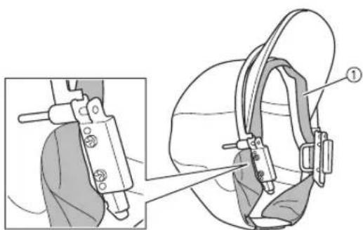
Attach the brim protector to the cap brim. Position the three retainers (center, left and right) of the brim protector under the cap brim, and perfectly align the brim protector with the upper frame.
①Retainers on brim protector
- Attaching the brim protector prevents the cap brim from rubbing against the machine and becoming damaged during sewing.
- If there is enough space between the cap brim and the machine, it may be possible to sew without the brim protector.

Note
Before sewing, be sure to check the.
embroidering area and confirm that the cap will not interfere with the machine. For details on checking the embroidered area, refer to the Operation Manual for the machine.
- If the cap brim interferes with the machine, the upper frame may not be securely pushed down. Refer to "Note" in step 6 of "Attach the cap to the cap frame" on page 8, and firmly push the upper frame down into the lower frame.
The cap is ready to be embroidered.
Removing the cap frame
After embroidering is finished, remove the cap frame, and then remove the cap.

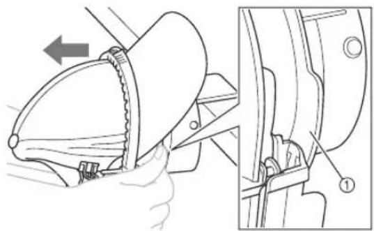
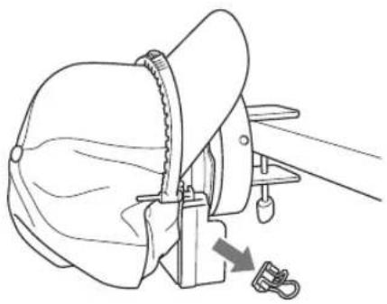
Remove the brim protector from the cap brim.
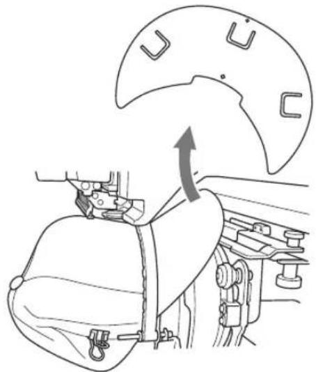

Remove the cap frame from the cap frame driver.
Grab the grips on both sides of the cap frame and pull off the frame as shown. It may be easier to remove the frame by applying force to one grip at a time.
①Grip
As shown, turn the embroidering area to the side when removing the cap frame so the brim of the cap does not hit the embroidery machine.
- Be careful that the cap frame does not hit any nearby parts, such as the presser foot.

Attach the cap frame to the mounting jig.
When positioning the lower frame of the cap frame, align the notch in the lower frame with the guiding plate at the center of the mounting jig.
①Guiding plate on mounting jig
②Notch in lower frame
③ Holders
The cap frame is secured with three holders.

Remove the clips from the cap.
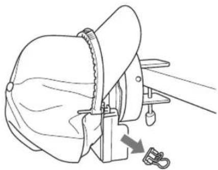

Set the lock knob on the lower frame to the unlocked position, and then remove the upper frame from the lower frame.
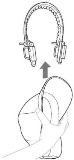
Grab the grips of the upper frame and remove the frame.
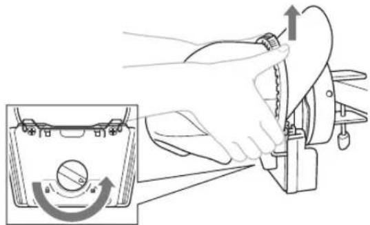

Lightly squeeze the brim of the cap and remove the upper frame from the cap.
Installing the embroidery frame holder
After embroidering using the cap frame is finished, remove the needle plate spacer and cap frame driver, and then re-attach the embroidery frame holder.

Remove the needle plate spacer.
①Needle plate spacer

Loosen the two lower thumb screws.
①Thumb screws

Remove the two upper thumb screws.
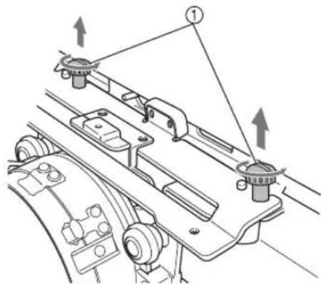
①Thumb screws

Remove the cap frame driver.

Note
- Be careful that the cap frame driver does not hit any nearby parts, such as the presser foot.

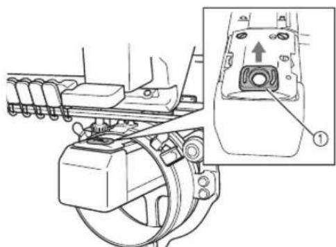
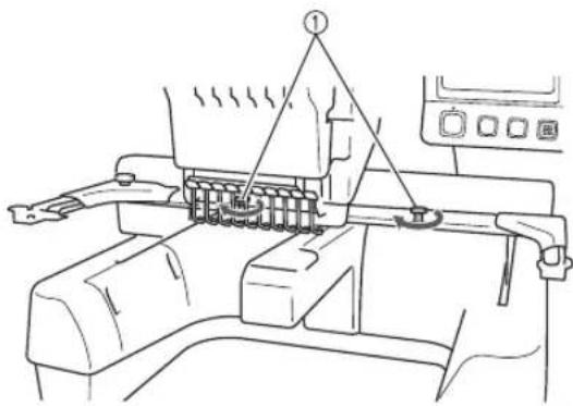
With the hole in the sweat guard holder of the cap frame driver aligned with the centerline of the center guiding plate, install the two thumb screws removed in step ③ in the holes at the top, and then tighten the thumb screws.
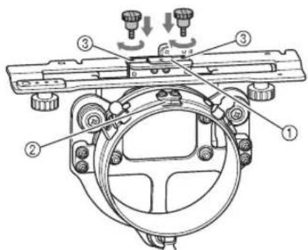
① Hole in the sweat guard holder
②Centerline of guiding plate
③ Holes at the top
- Install the thumb screws in the holes where the cap frame driver was originally installed.
The movable section of the cap frame driver is secured.

Align the holes in the embroidery frame holder with the pins on the frame-mounting plate of the carriage, and then secure the embroidery frame holder with the two thumb screws.
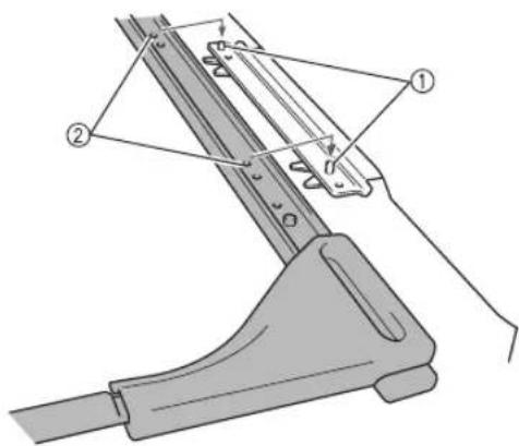
① Pins on the frame-mounting plate of the carriage
② Holes in the embroidery frame holder

Secure the embroidery frame holder with the two thumb screws.
① Use the thumb screws included with the machine.

CAUTION

- Firmly tighten the thumb screws.
Additional digitizing information
When creating a pattern for embroidering with the cap frame, pay attention to the following points in order to avoid registration problems (misalignment or gaps in the pattern).
1
Sew underlay stitches.
2
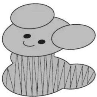
Start from the center of the embroidery pattern and sew toward the ends.
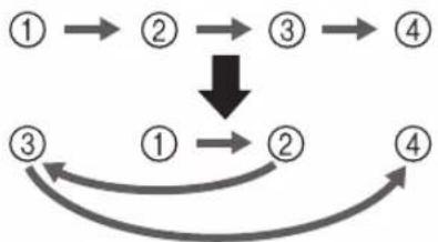
With this machine, the order in which patterns are selected when they are combined is the order in which they will be sewn. For the following example, select the patterns in the order "E" "A" "B" "R" to make the combined pattern "BEAR".
Incorrect sewing order
Correct sewing order


Note
- Do not sew from one end to the other, otherwise wrinkling or shrinkage may occur.

When sewing outlines of patterns, make sure that the stitch width of the satin stitching is at least 2mm and that the stitching overlaps the fabric by at least 1mm . Also, make sure that there are no long jumps stitches in the outlining of each region or letter.
① At least 1mm
② At least 2mm

CAUTION

- Do not sew more than four overlapping layers.
①Specify that overlapping areas are not sewn.
① Bande anti-transpiration
Remova as presilhas do bone.


- Cap frame and its accessories
- Cap frame: Upper frame/Lower frame
- Cap frame driver and 4 thumb screws
- Brim protector
- Mounting jig
- Allen screwdriver (large) Allen screwdriver (medium)
- Note
- Types of caps
- Standard (pro style)
- Low profile (low fitting)
- Flat visor
- Golf style
- Memo
- Caps not recommended for embroidering
- Fabric precautions
- Cap fabric recommended for embroidering
- Cap fabric not recommended for embroidering
- Preparing to use the cap frame
- ■ Installing the cap frame driver
- CAUTION
- Loosen the two thumb screws, and then remove the embroidery frame holder and thumb screws.
- Remove the two upper thumb screws of the cap frame driver, and then loosen the two lower thumb screws.
- Adjusting the cap frame driver
- Check that there is no looseness.
- Adjust the size of the mounting jig according to the type of cap being embroidered.
- For the standard type
- Removing the upper frame of the cap frame from the lower frame
- Remove the clips attached to the lower frame, and then set the lock knob to the unlocked position.
- Grab the grips of the upper frame and remove the upper frame from the lower frame.
- Attaching the cap frame
- While holding the upper frame and cap brim together, fit the remainder of the upper frame onto the base of the cap brim.
- ①Clip
- Remove the cap frame from the mounting jig.
- - Attaching the cap frame to the embroidery machine
- Attach the cap frame to the cap frame driver.
- Removing the cap frame
- Attach the cap frame to the mounting jig.
- Installing the embroidery frame holder
- Additional digitizing information
- Start from the center of the embroidery pattern and sew toward the ends.
Brand : BABY LOCK
Model : Array
Category : Embroidery machine