
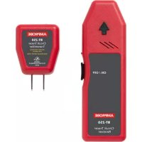
VPC30 - Electrical tester Amprobe - Free user manual and instructions
Find the device manual for free VPC30 Amprobe in PDF.
| Product Type | Voltage and Continuity Tester |
| Brand | Amprobe |
| Model | VPC30 |
| Maximum Voltage (AC/DC) | 1000 V |
| Safety Rating | CAT III 1000 V / CAT IV 600 V |
| Ingress Protection | IP65 (water and dust tight) |
| Display | LED indicators (10 levels AC and DC) |
| Power Supply | 2 AAA 1.5 V batteries (standard or alkaline) |
| Auto Power Off | After 25 seconds of inactivity |
| AC/DC Measurement Function | Auto-ranging, stepwise LED indicators |
| Continuity Test | Audible tone and LED indicator (threshold between 50 kΩ and 2000 kΩ) |
| Non-Contact EF Detection | Built-in antenna, audible tone and flashing proportional to field |
| AC Detection Vibrator | Signals AC voltage presence by vibration (threshold 8-15 V AC) |
| Input Impedance | 460 kΩ / 160 pF |
| AC Frequency Range | 45 Hz to 65 Hz |
| Operating Temperature | -10 °C to 55 °C |
| Relative Humidity | 20 % to 96 % |
| Double Insulation | Yes |
| Danger Indicator | Two-color indicator (red if >70 V DC or >33 V AC) |
| Maintenance | Clean with soft cloth and mild detergent; replace batteries |
| Repairability | User replaceable batteries; repair by authorized center |
| Warranty | 1 year against defects in materials and workmanship |
| Package Contents | Tester, fixed red probe, detachable black probe, instruction manual, 2 AAA batteries installed |
Frequently Asked Questions - VPC30 Amprobe
User questions about VPC30 Amprobe
0 question about this device. Answer the ones you know or ask your own.
Ask a new question about this device
Download the instructions for your Electrical tester in PDF format for free! Find your manual VPC30 - Amprobe and take your electronic device back in hand. On this page are published all the documents necessary for the use of your device. VPC30 by Amprobe.
USER MANUAL VPC30 Amprobe
Voltage & Continuity Tester
Users Manual
Mode d'emploi
Bedienungshandbuch
- Manual d'Uso
- Manual de uso
AMPROBE
VPC-30
VPC-31
Voltage & Continuity Tester
Users Manual
Limited Warranty and Limitation of Liability
Your Amprobe product will be free from defects in material and workmanship for 1 year from the date of purchase. This warranty does not cover fuses, disposable batteries or damage from accident, neglect, misuse, alteration, contamination, or abnormal conditions of operation or handling. Resellers are not authorized to extend any other warranty on Amprobe's behalf. To obtain service during the warranty period, return the product with proof of purchase to an authorized Amprobe Test Tools Service Center or to an Amprobe dealer or distributor. See Repair Section for details. THIS WARRANTY IS YOUR ONLY REMEDY. ALL OTHER WARRANTYES - WHETHER EXPRESS, IMPLIED OR STAUTORY - INCLUDING IMPLIED WARRANTYES OF FITNESS FOR A PARTICULAR PURPOSE OR MERCHANTABILITY, ARE HEREBY DISCLAIMED. MANUFACTURER SHALL NOT BE LIABLE FOR ANY SPECIAL, INDIRECT, INCIDENTAL OR CONSEQUENTIAL DAMAGES OR LOSSES, ARISING FROM ANY CAUSE OR THEORY. Since some states or countries do not allow the exclusion or limitation of an implied warranty or of incidental or consequential damages, this limitation of liability may not apply to you.
Repair
All test tools returned for warranty or non-warranty repair or for calibration should be accompanied by the following: your name, company's name, address, telephone number, and proof of purchase. Additionally, please include a brief description of the problem or the service requested and include the test leads with the meter. Non-warranty repair or replacement charges should be remitted in the form of a check, a money order, credit card with expiration date, or a purchase order made payable to Amprobe® Test Tools.
In-Warranty Repairs and Replacement – All Countries
Please read the warranty statement and check your battery before requesting repair. During the warranty period any defective test tool can be returned to your Amprobe® Test Tools distributor for an exchange for the same or like product. Please check the "Where to Buy" section on www.amprobe.com for a list of distributors near you. Additionally, in the United States and Canada In-Warranty repair and replacement units can also be sent to a Amprobe® Test Tools Service Center (see next page for address).
Non-Warranty Repairs and Replacement - US and Canada
Non-warranty repairs in the United States and Canada should be sent to a Amprobe® Test Tools Service Center. Call Amprobe® Test Tools or inquire at your point of purchase for current repair and replacement rates.
In USA In Canada
Amprobe Test Tools Amprobe Test Tools
Everett, WA 98203 Mississauga, ON L4Z 1X9
Tel: 888-993-5853 Tel: 905-890-7600
Fax: 425-446-6390 Fax: 905-890-6866
Non-Warranty Repairs and Replacement - Europe
European non-warranty units can be replaced by your Amprobe® Test Tools distributor for a nominal charge. Please check the "Where to Buy" section on www.amprobe.com for a list of distributors near you.
Amprobe® Test Tools Europe
In den Engematten 14
79286 Glottertal, Germany
tel: +49 (0) 7684 8009 - 0
*Correspondence only - no repair or replacement available from this address. European customers please contact your distributor.)customers please contact your distributor.)

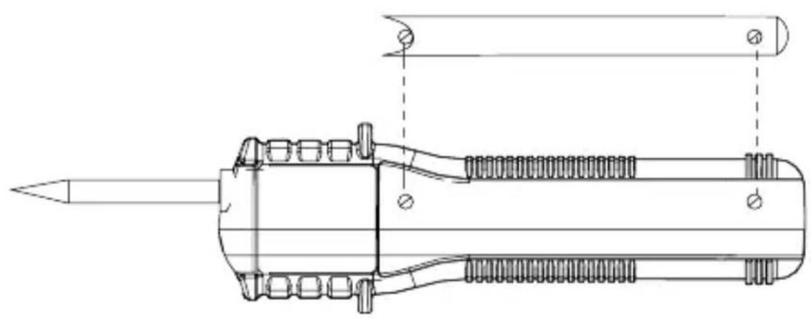
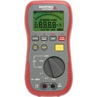
Screw-on 4mm test tip
Screw-on stationary Red test probe (+) for all functions
3 Detachable Black test probe (-) for all functions (Common ground reference)
EF-Detection (Non-Contact Voltage) antenna area
3 digits 1000 counts LCD display (VPC-31 only)
EF-Detection (Non-Contact & Probe-Contact) test button
GFCI Leakage-Path button (VPC-31 only)
8 LEDs
9 Input Jack (-) for Detachable Black test probe (Common ground reference)
CONTENTS
SYMBOLS 1
Safety Information 1
UNPACKING AND INSPECTION 3
INTRODUCTION 3
OPERATION 4
Indicator Self-Test 4
ACV () and DCV () measurements 4
GFCI Leakage-Path (VPC-31 only) 5
Overload-A Alert Warning 5
Bi-Color LED Hazardous Live Warning 6
Auto-Hold 6
AC-Detection Shaker 6
Electric Field EF-Detection 6
Audible Continuity Function 7
Auto Power On & Auto Power off (APO) 7
MAINTENANCE 7
Cleaning and Storage 7
Trouble Shooting. 8
Battery replacement 8
SPECIFICATIONS 9
General Specifications 9
Electrical Specification 10
AC Detection Shaker 11
Audible Continuity 11
Non-Contact EF-Detection 11
GFCI Leakage-Path (VPC-31 only) 11
MAINTENACE AND REPAIR 12
SYMBOLS
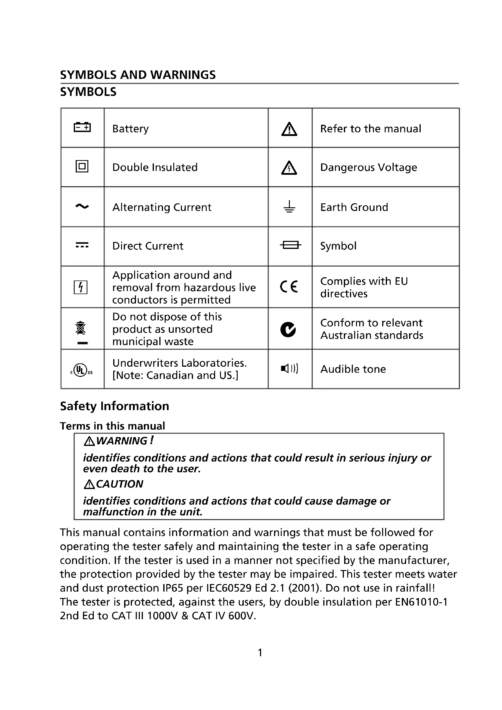
| -+ | Battery | Δ | Refer to the manual |
| ☐ | Double Insulated | Δ | Dangerous Voltage |
| ~ | Alternating Current | ± | Earth Ground |
| = | Direct Current | ≡ | Symbol |
| 4 | Application around and removal from hazardous live conductors is permitted | CE | Complies with EU directives |
| - | Do not dispose of this product as unsorted municipal waste | C | Conform to relevant Australian standards |
| cULus | Underwriters Laboratories. [Note: Canadian and US.] | ▲||| | Audible tone |
Safety Information
Terms in this manual
WARNING!
identifies conditions and actions that could result in serious injury or even death to the user.
CAUTION
identifies conditions and actions that could cause damage or malfunction in the unit.
This manual contains information and warnings that must be followed for operating the tester safely and maintaining the tester in a safe operating condition. If the tester is used in a manner not specified by the manufacturer, the protection provided by the tester may be impaired. This tester meets water and dust protection IP65 per IEC60529 Ed 2.1 (2001). Do not use in rainfall! The tester is protected, against the users, by double insulation per EN61010-1 2nd Ed to CAT III 1000V & CAT IV 600V.
Per IEC61010-1 and IEC60664:
Measurement Category IV (CAT IV) is for measurements performed at the source of the low-voltage installation. Examples are electricity meters and measurements on primary overcurrent protection devices and ripple control units.
Measurement Category III (CAT III) is for measurements performed in the building installation. Examples are measurements on distribution boards, circuit-breakers, wiring, including cables, bus-bars, junction boxes, switches, socket-outlets in the fixed installation, and equipment for industrial use and some other equipment, for example, stationary motors with permanent connection to the fixed installation.
Measurement Category II (CAT II) is for measurements performed on circuits directly connected to the low voltage installation. Examples are measurements on household appliances, portable tools and similar equipment.
WARNING!
To reduce the risk of fire or electric shock, do not expose this product to rain or moisture. To avoid electrical shock hazard, observe the proper safety precautions when working with voltages above 60 VDC or 30 VAC rms. These voltage levels pose a potential shock hazard to the user.
Keep your hands/fingers behind the hand/finger barriers of the test probes that indicate the limits of safe access of the hand-held part during measurement. Inspect test probes, connectors, and probes for damaged insulation or exposed metal before using the tester. If any defects are found, replace them immediately.
The voltages marked on the tester are nominal voltages or nominal voltage ranges. The tester shall only be used on installations with the specified nominal voltages or nominal voltage ranges.
Your shipping carton should include:
1 VPC-30 or VPC-31 Voltage Tester
1 black Test lead
1 Users Manual
2 1.5V AAA LR03/NEDA 24A Batteries (Installed)
If any of the items are damaged or missing, return the complete package to the place of purchase for an exchange.
INTRODUCTION
The VPC-30 and VPC-31 voltage testers are designed to be rugged and easy to use for the testing of voltage and continuity. They come with a Built in shaker that provides the same functionality and feel as the older analog solenoid testers. Full input protection to CAT IV 600V / CAT III 1000V.
The features include:
- Super-bright bi-Color LED's indicates safe and dangerous voltages (above 55VDC or 30VAC)
- Auto hold feature - LED's stay illuminated for 10 sec retaining a reading after the tests are disconnected
- Solenoid tester-like shaker to indicate AC voltage presence
- Automatically turns ON and OFF for easy and quick measurements
- Non-contact voltage detection and GFCI test feature for testing GFCI receptacles and breakers
- Standard detachable test lead (black) for easy replacement with optional longer or specialized probe
- Self test feature provides necessary safety by assuring proper operation
- Automatically selects AC Voltage, DC Voltage or Continuity
-
LED's indicate 10 levels of AC and DC Voltages:
-
Volts (AC) 24, 48, 120, 208, 240, 277, 347, 480, 600, 1000
Volts (DC) 6, 12, 24, 36, 48, 60, 72, 110, 220, 380 -
Auto backlit LCD Digital Display for precise voltage measurements (VPC-31 only)
- Continuity buzzer and Visual continuity indication (LED)
Water and dust proof, IP65 design - Safety CAT IV 600 V, CAT III 1000 V
Note: All function operations described hereafter are via the stationary "Red" probe for positive (+) polarity and the detachable "Black" probe for Ground reference (-), or otherwise specified
WARNING!
- Accurate indication is assured only when use within the specified operating temperature range.
- Before using the Audible Continuity & EF-Detection features at locations with a high background noise level, it shall be determined whether the audible signal is perceptible. The audible indication is for information only; do not rely on it, especially in high background noise.
- The functioning of the tester shall be checked shortly before and after a test. If indication of one or more steps fails, or if no functioning is indicated, the tester shall no longer be used.
Indicator Self-Test
Short the two test probes together, the tester enters continuity function. The continuity LED will turn on and the beeper will sound. With the probes still shorted, press the EF button momentarily. The LEDs will illuminate for full indication check. Five voltage indicating bi-color LEDs will change from green to red. On the VPC-31, the LCD will turn on for full segment check. The x , + , - and LEDs flash twice additionally when the battery voltage is low. After the Self-test is finished in approximately 2 to 3 seconds, the tester resumes normal functions.
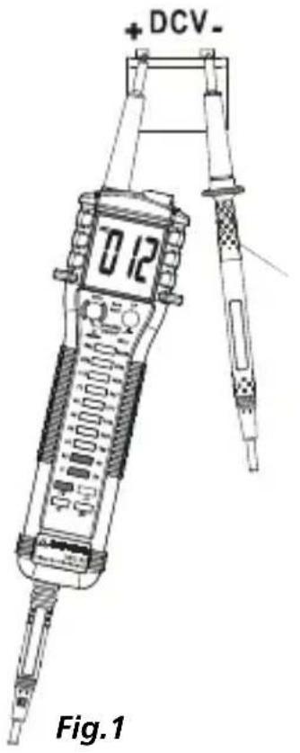
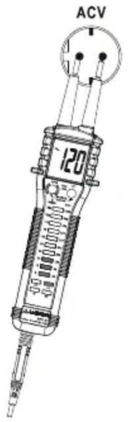
ACV () and DCV () measurements
Perform Indicator Self-Test as described. Test the tester on a known functioning circuit or component before and after performing measurements.
Connect test probes to voltage source and observe indication, as shown in Fig.1. Do not cover indicating LEDs (and also LCD on VPC-31) and do not touch the contact electrode before and during the tests. The tester turns on automatically at threshold voltages as specified in the specification section.
When significant ACV is being tested, LED turns on. When significant DCV is being tested, + LED turns on for correct test probes polarity, and -LED turns on for reversed polarity. Significant voltage levels are indicated as a series of LEDs in an auto-ranging manner. No manual-ranging selection is required. VPC-31 also indicates voltage levels on the automatic back lighted LCD.
The tester needs >7 seconds for the ACV "wake-up" measurement (also see Auto Power on & Auto Power Off section). Wake up the tester by shorting the two test probes together before making ACV measurements can improve the "wake-up" delay.
Note: The voltage indicating LEDs are all powered by the internal batteries, not by the system under test. The input impedance on voltage testing function is as high as 460kΩ , and hence the influence of the measuring current on the system under test is negligible. The peak occurring current IS at the highest rated voltage 1000VAC is: /s = 1000V × 1.414 / 460000Ω = 2.5mA
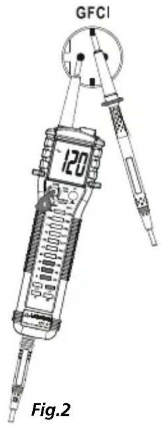
GFCI Leakage-Path (VPC-31 only) Refer to Fig.2
The tester equips with an GFCI Leakage-Path feature to load 120VAC/6mA GFCI (Ground-Fault Circuit Interrupter) circuit breakers. An internal leakage load path is provided when this feature is activated. Nominal load impedance is 16kΩ to provide typical leakage current of 7.5mA at 120VAC.
- Connect the tester to the receptacle under test by measuring the voltage across L and PE (live conductor and a protective earth ground). The tester should indicate proper line voltage level. (GFCI Leakage-Path feature is disabled above 132V and below 80V.)
- With the proper line voltage level still indicating, press and hold the GFCI button on the tester. The tester continuity/GFCI LED will turn on to indicate the internal leakage load path is being connected.
- The LED will turn off when the GFCI circuit breaker trips (line voltage is cut off). If a GFCI circuit breaker does not trip (within a fraction of a second) under such a leakage load condition, it is pretty sure that the breaker is not working properly or there is a wiring problem.
Note: This feature merely provides a handy leakage load path to load GFCI circuit breakers. It is not intended to identify the effectiveness (trip current and trip time etc as specified by the breaker manufacturers) of breakers even though the breakers trip under the above mentioned leakage conditions.
Overload-A Alert Warning
When the measured voltage exceeded 1000V AC or DC, the 1000V LED flashes. The VPC-31 LCD also displays "OL". Disconnect the test probes from the signal immediately to avoid hazards.
Bi-Color LED Hazardous Live Warning
The voltage LEDs are red if the measured voltage is above 70 VDC/33 VAC. These levels are deemed to be hazardous live in normal condition. Below these levels, the LEDs are green.
Auto-Hold
The LEDs flash the last significant measured value for approx. 10 seconds after a voltage measurement is made and removed via the test probes. The VPC-31 LCD also flashes the last significant measured value. Both test probes should be removed from the test points at about the same time (< 0.5 second in time difference) or else lower (intermittent) voltage might be measured.
AC-Detection Shaker
The shaker signals that significant ACV is being measured via the test probes.
With no input, press and hold the GFCI button and then followed by the EF button to toggle the shaker ON/OFF. The shaker will remain on until the buttons are released to confirm that the AC-Detection Shaker feature is enabled. The shaker will turn on briefly to signal that this feature has been disabled.
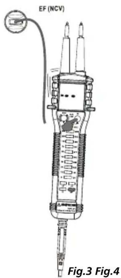
Electric Field EF-Detection Refer to Fig.3
Press and hold the EF button to enter and stay at EF-Detection feature. The EF-indicating LED will turn on briefly, and the beeper will give a short beep for EF indication check. Signal strength is indicated by beep tone and flashing of the EF LED. The VPC-31 also displays "EF" when it is ready, and displays signal strength as a series of bar-graph segments on the LCD.
- Non-Contact EF-Detection: An antenna is located along the top-right side of the meter, which detects electric field surrounds current-carrying conductors. It is ideal for tracing live wiring connections, locating wiring breakage and to distinguish between live or earth connections.
- Probe-Contact EF-Detection: For more precise indication of live wires, such as distinguishing between live and ground connections, use the Red (+) test probe for direct contact measurements.

Audible Continuity Function Refer to Fig.4
Short the two test probes together for continuity function check as described in Indicator Self-Test section. The continuity LED turns on together with a continuous beep tone indicates a complete circuit is being detected via the test probes. Audible-Continuity is convenient for checking wiring connections and operation of switches.
Auto Power On & Auto Power off (APO)
The tester turns on automatically and is ready for measurement within 1 second ( >7 seconds on ACV "wake-up" measurement) when making significant measurement or push button activity. Allow this delay on the "wake-up" measurement. Wake up the tester by shorting the two test probes together before making ACV measurements can improve the "wake-up" delay. The meter turns off automatically (APO) to extend battery life after approximately 25 seconds of no significant measurement or push button activity.
MAINTENANCE
WARNING!
To avoid electrical shock, disconnect the tester from any circuit and remove the test probes from the input jacks before opening the case and/or the battery access door. Do not use the tester with open case and/or the battery access door. Do not attempt to repair this unit. It contains no user-serviceable parts. Unauthorized persons shall not disassemble the tester.
Trouble Shooting
If the tester fails to operate, check batteries, probes, etc., and replace as necessary. Double check operating procedure as described in this user's manual
If the tester voltage-continuity input has subjected to high voltage transient (mostly caused by lightning or switching surge to your system) by accident or abnormal conditions of operation, the series fusible resistors will be blown off (become high impedance) like fuses to protect the user and the tester. Most measuring functions through this input will then be open circuit. The series fusible resistors and the spark gaps should then be replaced by qualified technician. Refer to the LIMITED WARRANTY section for obtaining warranty or repairing service.
Battery replacement
The batteries should be checked before use. When the battery voltage is low, the , + , - or LED flashes under normal significant measurements. VPC-31 also displays low battery icon on the LCD under normal significant measurements. Replace the batteries ASAP to maintain tester accuracy and functionality. The tester uses two 1.5V batteries: Standard 1.5V AAA Size (NEDA 24G or IEC R03) battery X 2; or 1.5V AAA Size (NEDA 24A or IEC LR03) alkaline battery X 2.
Loosen the 2 screws from the battery access door of the case bottom. Lift the battery access door up. Replace the batteries. Re-fasten the screws.
SPECIFICATIONS
General Specifications
Display: 3 digits 1000 counts
Update Rate: 5 per second nominal
Operating Temperature: -10°C 55°C (14°F~131°F)
Relative Humidity: 20% 96%
Altitude: Operating below 2000m
Storage Temperature: -10°C 55°C (14°F~131°F), 20% ~ 96% R.H. (with battery removed)
Temperature Coefficient: Nominal 0.15 x (specified accuracy)/ ° C @ (-10°C ~ 18°C or 28°C ~ 55°C), or otherwise specified
Sensing: Average sensing
Measurement Category: CAT III 1000V & CAT IV 600V AC & DC
E.M.C.: Meets EN61326-1:2006 (EN55022, EN61000-3-2, EN61000-3-3, EN61000-4-2, EN61000-4-3, EN61000-4-4, , EN61000-4-5, EN61000-4-6, EN61000-4-8, EN61000-4-11):
For both models: Performance is specified in an RF Field of 3V / m . Performance above 3V / m is not specified.
For VPC-31 LCD display only: In an RF Field of 3V / m , total accuracy = Specified accuracy + 45d. Performance above 3V / m is not specified
Type of Protection: IP65
Pollution Degree: 2
Safety: Meets EN61010-1 and IEC61010-1 2nd Edition to CAT III 1000V & CAT IV 600V
Transient Protection: 8kV lightning surge (1.2/50μs)
Overload Protection: 1000VDC & VAC rms
Low Battery: Below approx. 2.4V; Below approx. 2.6V with shaker ON
Power Supply: Standard 1.5V AAA Size (NEDA 24G or IEC R03) battery X 2; or 1.5V AAA Size (NEDA 24A or IEC LR03) alkaline battery X 2
APO Timing: Idle for 25 seconds
Power Consumption (typical): 3mA at Power-on ready; 25mA at 1000VAC full LED indication. 75mA at 1000VAC with shaker ON
APO Consumption (typical): 10µA
Dimension: 233 × 57 × 40mm (9.17 x 2.24 x 1.57 IN)
Weight: Approx. 220 g (0.485 lb)
Special Features: High Input Impedance, Indicator Self-Test, Auto-Hold, Overload-A Alert Warning, EF-Detection, AC-Detection Shaker, Bi-Color LED Hazardous Live Warning, and GFCI Trip Test (VPC-31 only)
Electrical Specification
Accuracy is given as +/- (\% of reading digits + number of digits) or otherwise specified @ 23°C + / - 5°C and less than 75% R.H.
| DC & AC Voltage (LED) | |||
| DCV MARKING Typical Threshold AC | MARKING Typical | Threshold | |
| 6V 5V 24V | 19V | ||
| 12V 10V 48V | 38V | ||
| 24V 19V 120V | 96V | ||
| 36V 30V 208V | 166V | ||
| 48V 42V 240V | 224V | ||
| 60V 54V 277V | 259V | ||
| 72V 66V 347V | 312V | ||
| 110V 91V 480V | 414V | ||
| 220V 176V 600V | 540V | ||
| 380V 304V 1000V | 800V | ||
DCV Tolerance: + / - (1% +2V)
ACV Tolerance: + / - (2.5% +4V)
Input Impedance: 460kΩ 160pF nominal
ACV Frequency Response: 45Hz 65Hz
Duty ratio: Continuous duty
| DC & AC Voltage (VPC-31 LCD only) | ||
| RANGE Threshold Accuracy | ||
| DC 999V > +4.5VDC or < | -4.5VDC 1.0%+2d | |
| AC 999V (50Hz/60Hz) > 8 | VAC 2.5%+4d | |
Input Impedance: 460kΩ 160pF nominal
ACV Frequency Response: 45Hz 65Hz
Duty ratio: Continuous duty
AC Detection Shaker
Shaker ON Threshold: between 8VAC and 15VAC

Audible Continuity
Open Circuit Voltage: 0.4VDC typical
Audible Threshold: between 50kΩ and 2000kΩ
Non-Contact EF-Detection
Indication: EF LED flashing & audible beep tones proportional to the field strength
Detection Frequency: 50/60Hz
Detection Antenna: Top-right side of the meter
Probe-Contact EF-Detection: For more precise indication of live wires, such as distinguishing between live and ground connections, use the Red (+) test probe for direct contact measurements.
VPC-31 also displays Bar graph segments proportional to the field strength on LCD. Typical values are shown in the below table:
| Typical Non-Contact Voltage Range | LCD Bar Graph Indication(VPC-31 only) |
| 15V to 55V - | |
| 30V to 95V - - | |
| 55V to 170V - - - | |
| Above 120V - - - - |
GFCI Leakage-Path (VPC-31 only)
Load Current: 7.5mA typical at 120V
Path Impedance: 16kΩ nominal, PTC protected
GFCI Leakage-Path feature is intended for 120V nominal circuits only. It is disabled above 132V and below 80V
If there appears to be a malfunction during the operation of the meter, the following steps should be performed in order to isolate the cause of the problem.
- Check the battery. Replace the battery immediately when the symbol "E+” appears on the LCD.
- Review the operating instructions for possible mistakes in operating procedure.
Except for the replacement of the battery, repair of the meter should be performed only by a Factory Authorized Service Center or by other qualified instrument service personnel. The front panel and case can be cleaned with a mild solution of detergent and water. Apply sparingly with a soft cloth and allow to dry completely before using. Do not use aromatic hydrocarbons or chlorinated solvents for cleaning.

VPC-30
VPC-31
©2009 Amprobe Test Tools.
Amprobe Test Tools Amprobe Test Tools
Everett, WA 98203 Mississauga, ON L4Z 1X9
Tél.: 888-993-5853 Tél.: 905-890-7600
Fax:425-446-6390 Fax:905-890-6866
APO Consumption (typical) : 10 μA
Dimensions: 233 × 57 × 40 mm (9,17 × 2,24 × 1,57 po.)
Poids : Environ 220 g (0,485 lb)
Amprobe Test Tools Amprobe Test Tools
Everett, WA 98203 Mississauga, ON L4Z 1X9
Tel.: 888-993-5853 Tel.: 905-890-7600
Fax: 425-446-6390 Fax: 905-890-6866
©2009 Amprobe Test Tools.
Amprobe Test Tools Amprobe Test Tools
Everett, WA 98203 Mississauga, ON L4Z 1X9
Tel.: 888-993-5853 Tel.: 905-890-7600
Fax: 425-446-6390 Fax: 905-890-6866
Amprobe Test Tools Amprobe Test Tools
Everett, WA 98203 Mississauga, ON L4Z 1X9
Tel.: 888-993-5853 Tel.: 905-890-7600
Fax: 425-446-6390 Fax: 905-890-6866
Visit www.Amprobe.com for
- Catalog
Application notes - Product specifications
- User manuals
- USERS MANUAL
- AMPROBE
- VPC-30
- VPC-31
- VOLTAGE & CONTINUITY TESTER
- LIMITED WARRANTY AND LIMITATION OF LIABILITY
- REPAIR
- IN-WARRANTY REPAIRS AND REPLACEMENT – ALL COUNTRIES
- NON-WARRANTY REPAIRS AND REPLACEMENT - US AND CANADA
- NON-WARRANTY REPAIRS AND REPLACEMENT - EUROPE
- CONTENTS
- SYMBOLS
- SAFETY INFORMATION
- TERMS IN THIS MANUAL
- PER IEC61010-1 AND IEC60664
- WARNING
- INTRODUCTION
- INDICATOR SELF-TEST
- ACV () AND DCV () MEASUREMENTS
- GFCI LEAKAGE-PATH (VPC-31 ONLY) REFER TO FIG.2
- OVERLOAD-A ALERT WARNING
- BI-COLOR LED HAZARDOUS LIVE WARNING
- AUTO-HOLD
- AC-DETECTION SHAKER
- ELECTRIC FIELD EF-DETECTION REFER TO FIG.3
- AUDIBLE CONTINUITY FUNCTION REFER TO FIG.4
- AUTO POWER ON & AUTO POWER OFF (APO)
- MAINTENANCE
- TROUBLE SHOOTING
- BATTERY REPLACEMENT
- SPECIFICATIONS
- GENERAL SPECIFICATIONS
- ELECTRICAL SPECIFICATION
- AC DETECTION SHAKER
- AUDIBLE CONTINUITY
- NON-CONTACT EF-DETECTION
- GFCI LEAKAGE-PATH (VPC-31 ONLY)
- VISIT WWW.AMPROBE.COM FOR
Brand : Amprobe
Model : VPC30
Category : Electrical tester