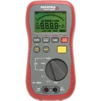
BT250 - Electrical tester Amprobe - Free user manual and instructions
Find the device manual for free BT250 Amprobe in PDF.
User questions about BT250 Amprobe
0 question about this device. Answer the ones you know or ask your own.
Ask a new question about this device
Download the instructions for your Electrical tester in PDF format for free! Find your manual BT250 - Amprobe and take your electronic device back in hand. On this page are published all the documents necessary for the use of your device. BT250 by Amprobe.
USER MANUAL BT250 Amprobe
All rights reserved. Printed in China
Limited Warranty and Limitation of Liability
Your Amprobe product will be free from defects in material and workmanship for one year from the date of purchase unless local laws require otherwise. This warranty does not cover fuses, disposable batteries or damage from accident, neglect, misuse, alteration, contamination, or abnormal conditions of operation or handling. Resellers are not authorized to extend any other warranty on the behalf of Amprobe. To obtain service during the warranty period, return the product with proof of purchase to an authorized Amprobe Service Center or to an Amprobe dealer or distributor. See Repair Section for details. THIS WARRANTY IS YOUR ONLY REMEDY. ALL OTHER WARRANTYES - WHETHER EXPRESS, IMPLIED OR STATUTORY - INCLUDING IMPLIED WARRANTY OF FITNESS FOR A PARTICULAR PURPOSE OR MERCHANTABILITY, ARE HEREBY DISCLAIMED. MANUFACTURER SHALL NOT BE LIABLE FOR ANY SPECIAL, INDIRECT, INCIDENTAL OR CONSEQUENTIAL DAMAGES OR LOSSES, ARISING FROM ANY CAUSE OR THEORY. Since some states or countries do not allow the exclusion or limitation of an implied warranty or of incidental or consequential damages, this limitation of liability may not apply to you.
Repair
All Amprobe returned for warranty or non-warranty repair or for calibration should be accompanied by the following: your name, company's name, address, telephone number, and proof of purchase. Additionally, please include a brief description of the problem or the service requested and include the test leads with the meter. Non-warranty repair or replacement charges should be remitted in the form of a check, a money order, credit card with expiration date, or a purchase order made payable to Amprobe.
In-warranty Repairs and Replacement - All Countries
Please read the warranty statement and check your battery before requesting repair. During the warranty period, any defective test tool can be returned to your Amprobe distributor for an exchange for the same or like product. Please check the "Where to Buy" section on amprobe.com for a list of distributors near you. Additionally, in the United States and Canada, in-warranty repair and replacement units can also be sent to an Amprobe Service Center (see address below).
Non-warranty Repairs and Replacement - United States and Canada
Non-warranty repairs in the United States and Canada should be sent to an Amprobe Service Center. Call Amprobe or inquire at your point of purchase for current repair and replacement rates.
USA: Canada:
Amprobe
Amprobe
Everett, WA 98203 Mississauga, ON L4Z 1X9
Tel: 877-AMPROBE (267-7623) Tel: 905-890-7600
Non-warranty Repairs and Replacement - Europe
European non-warranty units can be replaced by your Beha-Amprobe distributor for a nominal charge. Please check the "Where to Buy" section on beha-amprobe.com for a list of distributors near you.
Beha-Amprobe
Division and reg. trademark of Fluke Corp. (USA)
Germany United Kingdom The Netherlands - Headquarters*
In den Engematten 1452 Hurricane Way Science Park Eindhoven 5110
79286 Glottertal Norwich, Norfolk 5692 EC Son
Germany NR6 6JB United Kingdom The Netherlands
Phone: +49 (0) 7684 8009 - 0 Phone: +44 (0) 1603 25 6662 Phone: +31 (0) 40 267 51 00
beha-amprobe.de
beha-amprobe.com
beha-amprobe.com
*Correspondence only - no repair or replacement available from this address. European customers please contact your distributor.)
**single contact address in EEA Fluke Europe BV
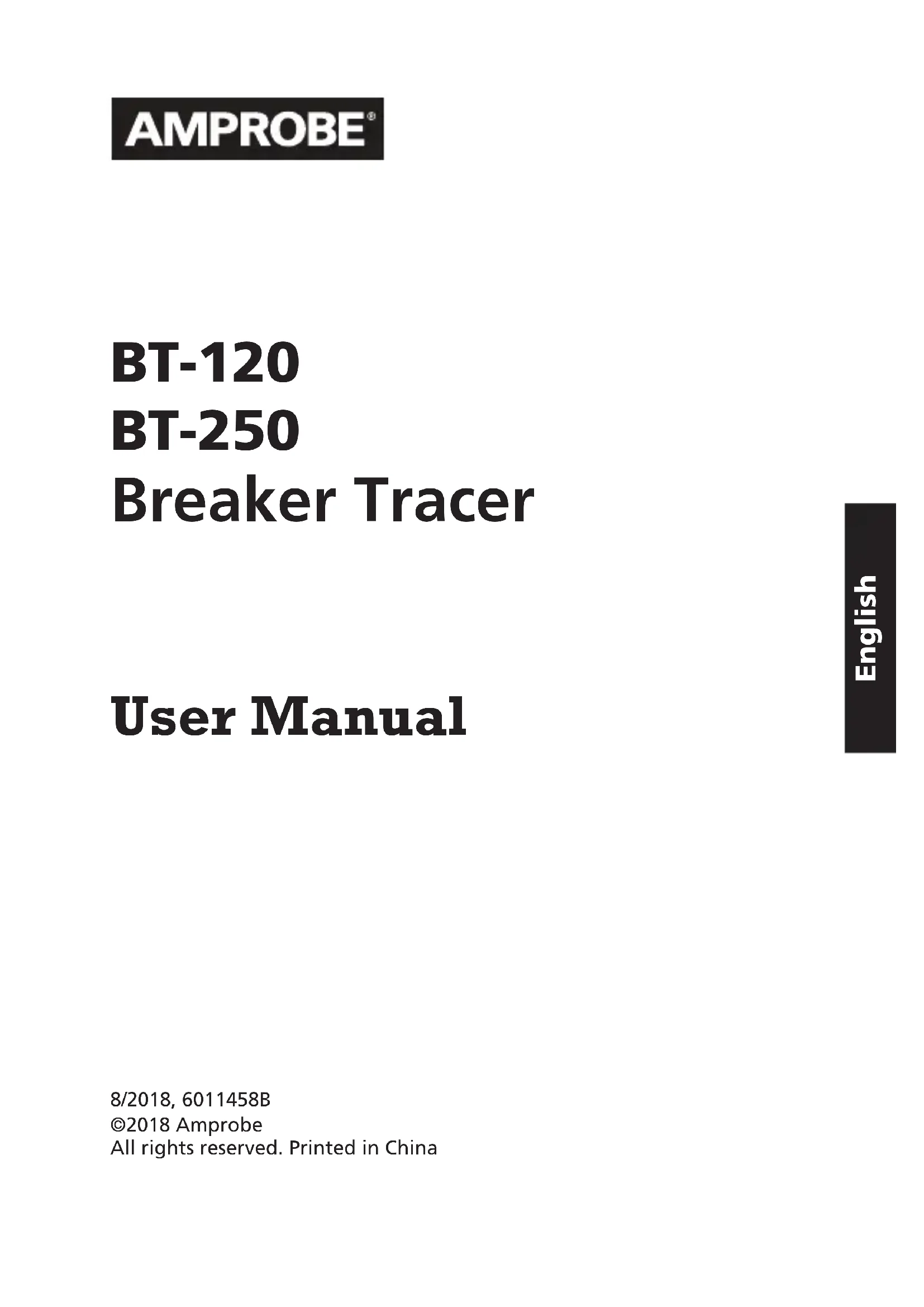
Sensor Location
Identification Arrow LED Indicator
3 Battery Compartment
ON/OFF Switch
Adaptor Prongs
6 Transmitter Power LED Indicator
7 Receiver Power LED Indicator
CONTENTS
SYMBOLS AND WARNINGS 2
Safety Information 2
Warnings and Precautions 3
UNPACKING AND INSPECTION 3
INTRODUCTION 4
OPERATION 4
SPECIFICATION 5
BATTERY REPLACEMENT 7
MAINTENANCE AND REPAIR 7
SYMBOLS
| - + | Battery |  | Caution ! Refer to the Manual |
|  | Double Insulated |  | Dangerous Voltage |
| ~ | Alternating Current |  | Earth Ground |
| - | Direct Current |  | Fuse |
|  | Application around and removal from hazardous live conductors is permitted | C € | Complies with European Directives |
|  | Do not dispose of this product as assorted municipal waste. Contact a qualified recycler for disposal. |  | Conforms to relevant Australian standards |
|  | Underwriters Laboratories. [Note: Canadian and US.] |  | Audible tone |
Safety Information
- The BT-120 Breakers Tester is conformed to UL 61010-1; CAT II 120 V, class II and pollution degree 1 or 2.
- The BT-250 Breakers Tester is conformed to UL 61010-1; CAT II 250 V, class II and pollution degree 1 or 2.
Warning and precaution
- Before and after hazardous voltage measurements, test the voltage function on a known source such as line voltage to determine proper meter functioning.
- Do not touch the membrane.
- Inspect the receiver and the transmitter before every use. Do not use any damaged part.
- Never ground yourself when taking measurements. Do not touch exposed circuit elements or test probe tips.
-
Do not operate the instrument in an explosive atmosphere.
-
To reduce the risk of fire or electric shock, do not expose this product to rain or moisture.
- The meter is intended only for indoor use. To avoid electrical shock hazard, observe the proper safety precautions when working with voltages above 60 VDC, 42.4 Vpk, or 30 VAC rms. These voltage levels pose a potential shock hazard to the user.
UNPACKING AND INSPECTION
Your shipping carton should include:
1 Receiver
1 Transmitter
1 9V alkaline battery
1 User manual
1 Carrying case (BT-250)
1 Connection cable (BT-250)
1 Light fixture adapter (BT-250)
If any of the items are damaged or missing, return the complete package to the place of purchase for an exchange.
INTRODUCTION
The Amprobe BT Series Breaker Tracers work on powered systems from 90 to 120 V AC (BT-120) and 90 to 250 V AC (BT-250) and are designed for use in residential and light commercial environments. Both kits comes complete with a Transmitter and Receiver.
Features:
- Identifies circuit breaker location
- Works on all electrical systems within the voltage rating range
- Perfect for office, residential and HVAC applications
Automatic sensitivity adjustment - Microprocessor controlled
- Extremely accurate reading always finds the right breaker
- Durable and dependable
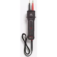
Breaker and Fuse Identification
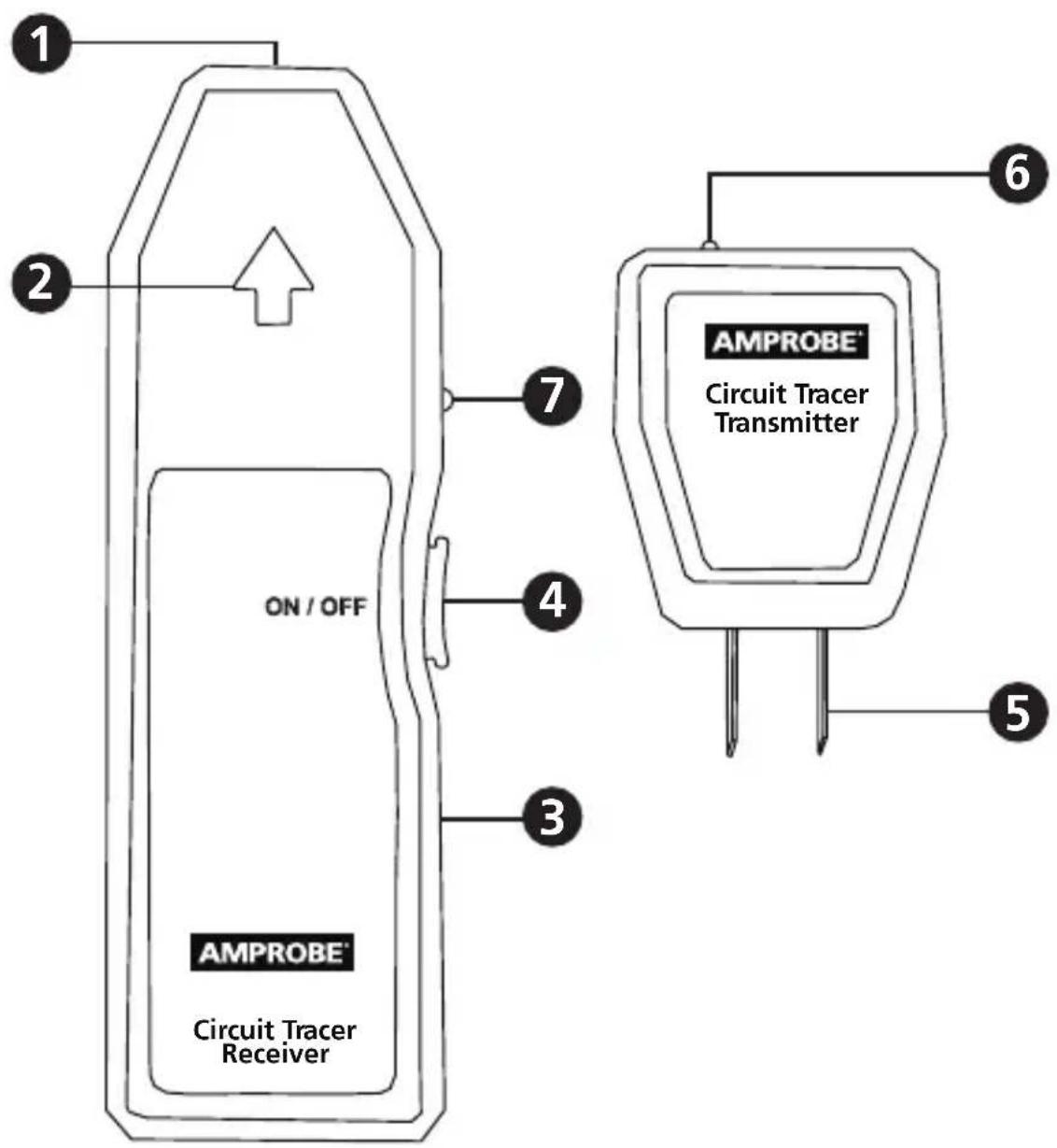
- Plug the Transmitter into an energized wall outlet (Figure 1).
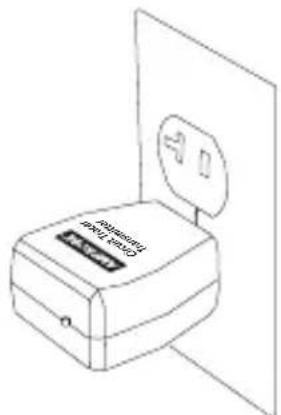
Figure 1
- Make sure the red LED is ON to indicate that the outlet is energized.
- Push the Power switch on the Receiver to turn it ON. The Receiver will beep and the Power LED will be lit.
- At the breaker panel or fuse box, hold the Receiver perpendicular to the breakers. Scan slowly all breakers once to calibrate the Receiver. During this scan, the Receiver may beep and flash at several breakers. This is a normal part of the identification process (Figure 2).
Figure 2
- Without touching the ON/OFF button, begin scanning again to identify the right breaker or fuse. When the Receiver beeps, the correct breaker has been identified.
- Push and hold the Power switch for three seconds to turn the Receiver off. Beeping and flashing during the shutdown is normal.
- Unplug the Transmitter from the wall outlet.
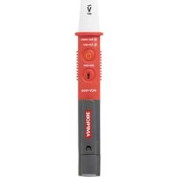
Using the BT-LFA Incandescent Light Fixture Adapter (BT-250 only)
- Remove the light bulb exercising the proper caution.
- Screw in the BT-LFA adapter.
- Plug the Transmitter into the BT-LFA (Figure 3).
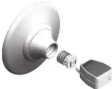
Figure 3
- Preform scan following directions in step 4 under "Operation."
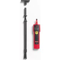
Using the BT-VLA High Voltage Leads Adapter (BT-250 only)
The BT-250 Transmitter can be used alone on 110V circuits. For circuits up to 250V or exposed circuits, use the BT-VLA and follow the directions listed below.
- Plug Transmitter into high voltage lead receptacle. Be sure that the Transmitter is completely seated and that no part of the Transmitter prongs are exposed.
- Attach the high voltage leads to the terminal or conductor while exercising extreme caution (Figure 4).
- Preform scan following directions in step 4 under "Operation."
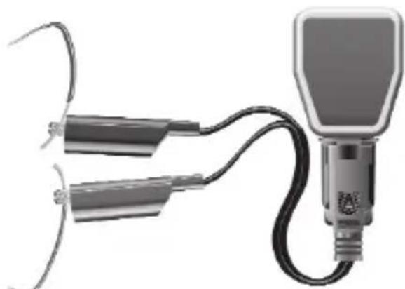
Figure 4
SPECIFICATIONS
| Operating & Detection BT | -120 BT-250 | |
| Voltage for Transmitter | 90-120 VAC, Not to exceed ±10% (inclusive in rating) | 90-250 VAC, Not to exceed ±10% (inclusive in rating) |
| Operating Frequency 50 Hz to 60 Hz 40 Hz to 70 Hz | ||
| Storage Temperature 32 °F to 104 °F (0 °C to 40 °C) | ||
| Operating Temperature 32 °F to 104 °F (0 °C to 40 °C) | ||
| Sensitivity Adjustment Automatic | ||
| Power Supply 9 V alkaline battery (Receiver) | ||
| Transmitter Polarity Automatic | ||
| Humidity 50% RH (non condensing) | ||
| Environmental Conditions | Indoor use, altitudes up to 2000 m, Pollution Degree 1 or 2, Installation Category II | |
| Caution | BT-VLA cord assembly to be used with Transmitter only according to instructions. | |
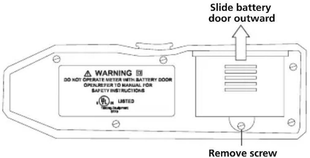
BATTERY REPLACEMENT
Power is supplied by one 9 V alkaline battery (Receiver).
The Identification Arrow LED on the Receiver will not turn ON when replacement is needed. To replace the battery, remove the screw from the back of the meter and slide the battery door outward. Remove the battery from case bottom and replace it with a fresh 9 V alkaline battery.
If there appears to be a malfunction during the operation of the tracer, the following steps should be performed in order to isolate the cause of the problem.
- Check the battery. Replace the battery immediately if the Receiver LED doesn't turn ON.
- Review the operating instructions for possible mistakes in operating procedure.
Except for the replacement of the battery, repair of the tracer should be performed only by a Factory Authorized Service Center or by other qualified instrument service personnel.
The front panel and case can be cleaned with a mild solution of detergent and water. Apply sparingly with a soft cloth and allow to dry completely before using. Do not use aromatic hydrocarbons or chlorinated solvents for cleaning.
BT-120
BT-250
REEMPLAZO DE LA PILA
Visit amprobe.com for
- Catalog
Application notes
Product specifications - User manuals
Amprobe
amprobe.com
Division of Fluke Corp.
6920 Seaway Blvd.
M/S 143F
Everett, WA 98203 USA
Tel: 877-AMPROBE (267-7623)
Beha-Amprobe
beha-amprobe.com
c/o Fluke Europe BV
Science Park
Eindhoven 5110
NL-5692 EC Son
Tel.: +49 (0) 7684 8009 - 0

Please
Recycle