IAN 309489 - Bathroom faucets MIOMARE - Free user manual and instructions
Find the device manual for free IAN 309489 MIOMARE in PDF.
User questions about IAN 309489 MIOMARE
0 question about this device. Answer the ones you know or ask your own.
Ask a new question about this device
Download the instructions for your Bathroom faucets in PDF format for free! Find your manual IAN 309489 - MIOMARE and take your electronic device back in hand. On this page are published all the documents necessary for the use of your device. IAN 309489 by MIOMARE.
USER MANUAL IAN 309489 MIOMARE
text_image
PDF ONLINE www.lidl-service.comWANNENFÜLLARMATUR MIT HANDBRAUSE / BATHTUB MIXER TAP WITH SHOWER HEAD / ROBINETTERIE DE BAIGNOIRE AVEC DOUCHETTE
DE AT CH
WANNENFÜLLARMATUR MITHANDBRAUSE
Assembly, operating and safety instructions
NL BE
BADKUIPKRAANMET HANDDOUCHE
Before reading, unfold the page containing the illustrations and familiarise yourself with all functions of the device.
FR BE
GB / IE Assembly, operating and safety instructions Page 11
(Wasseranschlüsse): G 3/4"
Brauseschlauch-
Anschluss: G 1/2"
Intended use....Page 12
Parts description Page 12
Technical Data Page 12
Scope of delivery....Page 12
Safety information......Page 12
Installation......Page 13
Connecting the fitting....Page 13
Connecting accessories (shower hose and shower head)......Page 13
Mounting the wall bracket Page 13
Operation Page 14
Start-up......Page 14
Tub filler / shower diverter Page 14
Maintenance and cleaning......Page 14
Maintaining and cleaning the tap Page 14
Replacing the cartridge Page 14
Disposal Page 15
Information......Page 15
Potability of tap water......Page 15
Warranty and service......Page 15
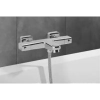
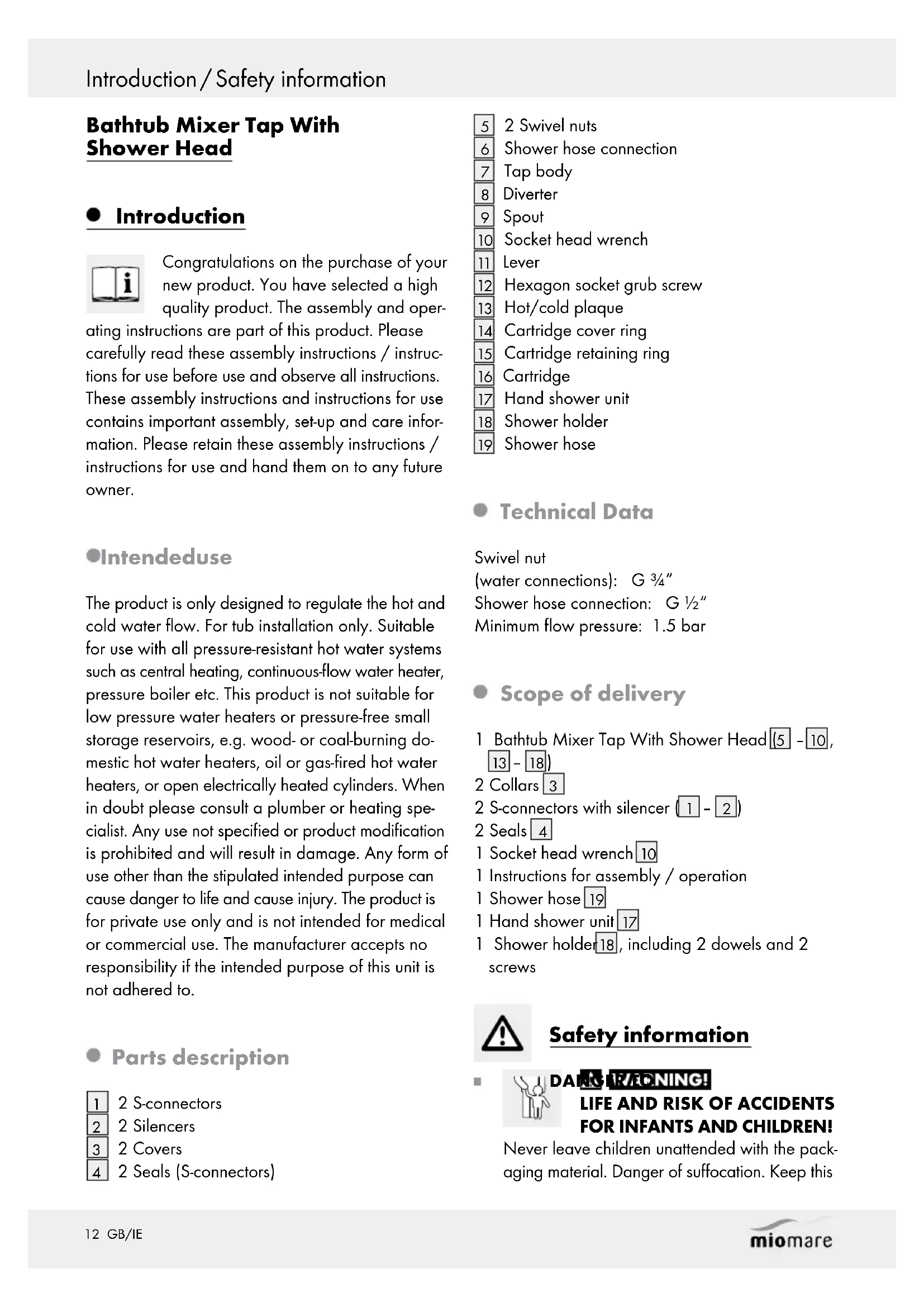
Bathtub Mixer Tap With Shower Head
- Introduction

Congratulations on the purchase of your new product. You have selected a high quality product. The assembly and operating instructions are part of this product. Please carefully read these assembly instructions / instructions for use before use and observe all instructions. These assembly instructions and instructions for use contains important assembly, set-up and care information. Please retain these assembly instructions / instructions for use and hand them on to any future owner.
Intendeduse
The product is only designed to regulate the hot and cold water flow. For tub installation only. Suitable for use with all pressure-resistant hot water systems such as central heating, continuous-flow water heater, pressure boiler etc. This product is not suitable for low pressure water heaters or pressure-free small storage reservoirs, e.g. wood- or coal-burning domestic hot water heaters, oil or gas-fired hot water heaters, or open electrically heated cylinders. When in doubt please consult a plumber or heating specialist. Any use not specified or product modification is prohibited and will result in damage. Any form of use other than the stipulated intended purpose can cause danger to life and cause injury. The product is for private use only and is not intended for medical or commercial use. The manufacturer accepts no responsibility if the intended purpose of this unit is not adhered to.
- Parts description
1 2 S-connectors
2 2 Silencers
3 2 Covers
4 2 Seals (S-connectors)
5 2 Swivel nuts
6 Shower hose connection
7 Tap body
8 Diverter
9 Spout
10 Socket head wrench
11 Lever
12 Hexagon socket grub screw
13 Hot/cold plaque
14 Cartridge cover ring
15 Cartridge retaining ring
16 Cartridge
17 Hand shower unit
18 Shower holder
19 Shower hose
- Technical Data
Swivel nut
(water connections): G 34 "
Shower hose connection: G 1/2"
Minimum flow pressure: 1.5 bar
- Scope of delivery
1 Bathtub Mixer Tap With Shower Head (5 - 10, 13 - 18)
2 Collars 3
2 S-connectors with silencer (1 - 2)
2 Seals 4
1 Socket head wrench 10
1 Instructions for assembly / operation
1 Shower hose 19
1 Hand shower unit 17
1 Shower holder[18], including 2 dowels and 2 screws

Safety information


DANG IR/IONING!
LIFE AND RISK OF ACCIDENTS FOR INFANTS AND CHILDREN!
Never leave children unattended with the packaging material. Danger of suffocation. Keep this
product well away from children. This product is not a toy.
■
BEWARE OF ELECTRIC SHOCK!
Leaking or water discharge can lead to life-threatening danger due to electric shock. Carefully check that all connections are watertight. Also ensure that all wires of electric appliances are correct and have been securely installed.
△
CAUTION! RISK OF INJURY! Please ensure that no parts are damaged and that all parts are correctly assembled. Incorrect assembly could lead to injury. Please note that washers and gaskets are wear parts and therefore will need to be replaced from time to time. Damaged parts could impact safety and function.
■
CAUTION! DAMAGE TO THE ARTICLE!
Please have all installations performed by skilled individuals.
■
Be sure all seals are correctly seated.
■
SCALDINGRISK! When adjusting the hot water temperature be sure the water temperature is not too high.
!
AUTION! Be careful not to revere the hot / cold water plaque 13. The correct placement is: t = red (hot), ht = blue (cold).
■ Please note all seals are wear items and will therefore need to be replaced over time.
■ Any leakage or sudden escape of water can cause considerable damage to buildings and property. All connections must therefore be checked carefully to ensure that they are tight.
■ Familiarise yourself prior to installation with all local conditions, e.g. water connections and shut-off device.
The product is only suitable for use in rooms with a temperature above 0 °C.
Installation
Note: Familiarise yourself with the product prior to assembly. Carefully read the following assembly instructions and safety advice. In the event of incorrect installation, all warranty claims – particularly in relation to subsequent damage – are excluded.
■
CAUTION! Before you start installation turn off the water supply at the mains. Otherwise injuries and / or property damage may occur.
●
Connecting the fitting
Note: this step requires an SW 30 mm open-end spanner and sealing tape.
Note: cover any parts which will be screwed with a damp cloth or plastic clamps. This will prevent scratches.
Follow these steps:
Wrap sealing tape around the roughened threaded part ( 12 " thread) of the S-connectors 1.
Note: sealing tape not included.
Screw the S-connectors 1 with the sealed threaded parts into the wall connectors.
☐ Horizontally align the screwed in S-connectors
☐ with the spacing guide for the fitting.
Screw the caps 3 hand tight onto the S-connectors 1 to the wall.
☐ Insert the seals 4 into the swivel nuts 5 and screw the fitting body 7 with swivel nuts 5 onto the S-connectors 1.
●
Connecting accessories (shower hose and shower head)
Note: cover each of the parts which are to be screw connected with a damp cloth or plastic clips. This will prevent scratches.
Screw the shower hose 19 tightly to the shower hose connection 6.
Connect the shower head to the shower hose 19.
●
Mounting the wall bracket
☐ Mark the place where the 2 drill holes for the shower holder 18 will be drilled.
Installation / Operation / Maintenance and cleaning
Drill 2 drill holes with a 1 14 bit and insert the dowels into the drilled holes.
☐ Screw the shower holder 18 into the wall using the screws.
Operation
- Start-up
After the initial commissioning, carefully check all connections for leaks.
☐ Check the operation of the fitting. To do so, swing the handle 11 into all permissible positions.
Open the main water supply.
☐ Lift the handle 11 and swing it to the right or left in order to regulate the speed or temperature of the water.
Hot water:
Swing the handle 11 to the left.
Cold water:
Swing the handle 11 to the right.
- Tub filler / shower diverter
Manually switch between the tub spout and the shower function by pulling out and pressing down the diverter 8.
Tub spout:
Press down the diverter 8.
Shower function:
Pull out the diverter 8.
Note: If the water is shut off when the shower function is activated, it will be switched to the tub spout the next time the product is used.
● Maintenance and cleaning
●Maintaining and cleaning the tap
Please note that sanitary taps require special care and attention. Therefore, please follow the instructions:
When cleaning, never use petrol, solvents, aggressive cleansers or hard cleaning brushes etc. These could damage the surface of the product.
Dry your fitting with a cloth after every use to prevent any lime deposits.
□ Clean the product with a damp, soft cloth and a mild cleaning agent if required.
Non-observance of the above care advice can be expected to result in damage to the surfaces of the product. This will inevitably invalidate the guarantee.
- Replacing the cartridge
A cartridge 16 is a wear part that needs replacing according to the hardness and / or degree of contamination of the water. This becomes evident when the handle 11 becomes difficult to move. A new cartridges 16 can be obtained from the listed service office.
Note: this step requires an open-end spanner SW 27 mm or fitting pliers.
Proceed as follows to replace the cartridge 16:
☐ Shut off the main water supply. Allow any remaining water in the pipework to drain.
☐ Remove the hot / cold plaque 13 by inserting a flat object between the edge of the hot / cold plaque 13 and the outside of the handle 11.
Note: use light pressure to carefully push the hot/cold plaque 13 outward so as not to scratch the surface.
☐ Loosen the hexagon socket grub screw 12 with the socket head wrench 10 by turning it counterclockwise.
CAUTION! Do not unscrew the hexagon socket grub screw 12 completely. Only loosen this as far as is necessary to remove the lever 11.
Maintenance and cleaning / Disposal / Information / Warranty and service
Remove the handle 11.
□ Unscrew the cartridge covering ring 14, do not use pliers or a spanner. Otherwise the product could be damaged.
☐ Loosen the cartridge retaining ring 15 below with fitting pliers or a 27 mm open-end spanner and remove the entire cartridge 16 from the tap fitting 7.
☐ Insert the new cartridge 16 into the fitting body 7 in the same manner.
Note: be sure the seal under the cartridge is correctly seated. Make sure that the guides are in the corresponding holes.
☐ Reassemble all the parts stated above. Tighten the cartridge retaining ring 15 using fitting pliers or a 27 mm open-end spanner while simultaneously securing the fitting from twisting. This will guarantee that it is tight and ensure the lever is not difficult to move.
CAUTION! Be careful not to revere the hot/cold water plaque 13. The correct placement is: left = red (hot water), right = blue (cold).
- Disposal
The packaging is made of environmentally friendly materials, which may be disposed of through your local recycling facilities.
Contact your local refuse disposal authority for more details of how to dispose of your worn-out product.
Information
- Potability of tap water
Please consult your local authorities on the potability of water in your town / municipality.
The following general recommendations apply to the potability of tap water:
- Let the water run freely for a short time if it has been stagnating in the pipework for more than
four hours. Do not use any of this stagnant water in the preparation of food or for drinking. This applies particularly as far as babies and infants are concerned. Otherwise health concerns can arise. Fresh water can be readily distinguished from stagnant water as fresh water is noticeably cooler as it leaves the pipe.
Do not use stagnant water from chromium-plated pipework to prepare food, for drinking, or for personal hygiene if you are allergic to nickel. This water may contain high quantities of nickel and trigger an allergic reaction.
Do not use water from lead pipework for preparing food baby food and / or to prepare foods during pregnancy. Lead dissolves in drinking water and is particularly damaging to the health of babies and young children.
● Warranty and service
The product has been manufactured to strict quality guidelines and meticulously examined before delivery. In the event of product defects you have legal rights against the retailer of this product. Your legal rights are not limited in any way by our warranty detailed below.
The warranty for this product is 5 years from the date of purchase. Should this product show any fault in materials or manufacture within 5 years from the date of purchase, we will repair or replace it - at our choice - free of charge to you.
The warranty period begins on the date of purchase. Please keep the original sales receipt in a safe location. This document is required as your proof of purchase. This warranty becomes void if the product has been damaged, or used or maintained improperly.
The warranty applies to defects in material or manufacture. This warranty does not cover product parts subject to normal wear, thus possibly considered consumables (e.g. batteries) or for damage to fragile parts, e.g. switches, rechargeable batteries or glass parts.
Customer service
(Call charges are in accordance with the fixed line rates of your telephone provider)
Tel. +800 34 99 67 53 (from abroad)
Please have the receipt and item number, e.g.
IAN 12345 ready as your proof of purchase when making an enquiry.
Introduction......Page 18
Monter le support mural......Page 20
Utilisation......Page 20
PRENEZ GARDE AU RISQUE
- Monter le support mural
links = rood (warm water),