PFM42B2 - TV SONY - Free user manual and instructions
Find the device manual for free PFM42B2 SONY in PDF.
User questions about PFM42B2 SONY
0 question about this device. Answer the ones you know or ask your own.
Ask a new question about this device
Download the instructions for your TV in PDF format for free! Find your manual PFM42B2 - SONY and take your electronic device back in hand. On this page are published all the documents necessary for the use of your device. PFM42B2 by SONY.
USER MANUAL PFM42B2 SONY
Operating Instructions GB
Mode d'emploi FR
PFM-42B1/42B2 PFM-42B1E/42B2E
© 2000 Sony Corporation
安全のたに
八一-一-二-一-一-一-一-一-一-一-一-一-一-一-一-一-一-一-一-一-一-一-一-一-一
The model and serial numbers are located on the rear.
Record the model and serial numbers in the spaces provided below. Refer to these numbers whenever you call upon your Sony dealer regarding this product.
Model No. _ Serial No. _
To prevent fire or shock hazard, do not expose the unit to rain or moisture.
To avoid electrical shock, do not open the cabinet. Refer servicing to qualified personnel only.
For customers in the U.S.A.
If you have any questions about this product, you may call: Sony's Business Information Center (BIC) at 1-800-686-SONY (7669)
or Write to: Sony Customer Information Services Center 6900-29 Daniels Parkway, PMB 330 Fort Myers, Florida 33912
Declaration of Conformity
Trade Name:SONY
Model: PFM-42B1/42B2
Responsible Party: Sony Electronics Inc.
Address: 680 Kinderkamack Road,
Oradell NJ 07649 U.S.A.
Telephone Number: 201-930-6972
This device complies with Part 15 of the FCC Rules.
Operation is subject to the following two conditions: (1) This device may not cause harmful interference, and (2) this device must accept any interference received, including interference that may cause undesired operation.
This equipment has been tested and found to comply with the limits for a Class B digital device, pursuant to Part 15 of the FCC Rules. These limits are designed to provide reasonable protection against harmful interference in a residential installation. This equipment generates, uses, and can radiate radio frequency energy and, if not installed and used in accordance with the instructions, may cause harmful interference to radio communications. However, there is no guarantee that interference will not occur in a particular installation. If this equipment does cause harmful
interference to radio or television reception, which can be determined by turning the equipment off and on, the user is encouraged to try to correct the interference by one or more of the following measures:
- Reorient or relocate the receiving antenna.
- Increase the separation between the equipment and receiver.
- Connect the equipment into an outlet on a circuit different from that to which the receiver is connected.
- Consult the dealer or an experienced radio/TV technician for help.
You are cautioned that any changes or modifications not expressly approved in this manual could void your authority to operate this equipment.
For customers in Canada
This class B digital apparatus complies with Canadian ICES-003.
The socket-outlet should be installed near the equipment and be easily accessible.
Table of Contents
Precautions 5 (GB)
Features 6 (GB)
Location and Function of Parts and Controls .... 7 (GB)
Front / Rear / Right Side 7 (GB)
(standby) Switch/Indicator Section 8 (GB)
Control Button Section (Rear) 8 (GB)
Connector Panel 9 (GB)
Remote Commander RM-42B 11 (GB)
Caution 13 (GB)
Connections 14 (GB)
Connecting the AC Power Cord 14 (GB)
Attaching the ferrite core (PFM-42B2/42B2E only) 14 (GB)
Connection Example. 14 (GB)
Using On-screen Menus 19 (GB)
Operating Through Menus. 19 (GB)
Menu Guide 19 (GB)
Watching the Picture 23 (GB)
Switching the Input Signal. 23 (GB)
Switching the Display Mode. 24 (GB)
Input Signal and Display Status Information. 25 (GB)
Adjusting the Picture 27 (GB)
Adjusting the Contrast, Brightness, Chroma, and Phase, etc. 27 (GB)
Restoring the PIC CONTROL Menu Items to Their Original Settings 28 (GB)
Resizing and Positioning the Picture 29 (GB)
Resizing the Picture 29 (GB)
Adjusting the Picture Position 30 (GB)
Restoring the Original Picture Size and Position... 30 (GB)
Changing the Aspect Ratio. 31 (GB)
Adjusting the Linearities. 31 (GB)
Adjusting the Pixels 32 (GB)
Using the Memory Function 33 (GB)
Storing the Current Setting 33 (GB)
Calling Up a Stored Setting 34 (GB)
Selecting the On-screen Language 35 (GB)
Reducing Afterimage/Ghosting (Screen Saver Function) 36 (GB)
Reversing the Image 36 (GB)
Changing the Image Position Automatically 37 (GB)
Controlling Power On/Off Automatically (Power Control Function) 38 (GB)
Energy Saving Function (PFM-42B2/42B2E only) 38 (GB)
Power Saving Function 39 (GB)
On/Off Timer Function 39 (GB)
On Timer Function (PFM-42B2/42B2E only). 41 (GB)
Off Timer Function (PFM-42B2/42B2E only) .... 41 (GB)
Setting the SERIAL REMOTE (PFM-42B2/42B2E only). 42 (GB)
Setting the baud rate 42 (GB)
OSD Function 42 (GB)
Setting the NETWORK ADAPTOR (PFM-42B2/42B2E only). 43 (GB)
Setting the power supply to the Network Adaptor 43 (GB)
If the screen freezes when you use the Network Adaptor 43 (GB)
Self-diagnosis Function 44 (GB)
Operating a Specific Display With the Remote Commander 44 (GB)
Using Other Remote Commander Models 46 (GB)
Specifications 47 (GB)
Precautions
On safety
- A nameplate indicating operating voltage, power consumption, etc. is located on the back of the unit.
- Should any solid object or liquid fall into the cabinet, unplug the unit and have it checked by qualified personnel before operating it any further.
- Unplug the unit from the wall outlet if it is not to be used for several days or more.
- To disconnect the AC power cord, pull it out by grasping the plug. Never pull the cord itself.
- When the unit is installed on the floor, be sure to use the optional stand.
On installation
- A low adequate air circulation to prevent internal heat build-up. Do not place the unit on surfaces (rugs, blankets, etc.) or near materials (curtains, draperies) that may block the ventilation holes.
- Do not install the unit in a location near heat sources such as radiators or air ducts, or in a place subject to direct sunlight, excessive dust, mechanical vibration or shock.
- When you install multiple equipment with the unit, the following problems, such as malfunction of the Remote Commander, noisy picture, noisy sound, may occur depending on the position of the unit and other equipment.
On the PDP (Plasma Display Panel)
- The plasma display panel is manufactured using extremely high precision technology. However, black points may appear or may be seen on the screen, or bright points (white, red, blue or green) may remain on the screen, or some striped or color irregularities may be seen. These are not malfunctions.
-
If you continue to display the same image on the screen for a long period of time, part of that image may burn into a part of the panel, and leave a ghosting image behind. If you display the same image for a long period of time, to avoid burning this image into the panel, use the screen function provided, displaying it over the entire screen. If ghosting occurs, use the screen saver function, or use some kind of video or imaging software to provide constant movement on the screen. If light ghosting (image burn-in) occurs, it may become less conspicuous, but once burn-in occurs, it will never completely disappear.
-
Because of the way it is made, when this plasma display panel is used in places with low air pressure, such as at high altitudes, a buzzing or humming noise may emanate from the unit.
On cleaning
To keep the unit looking brand-new, periodically clean it with a mild detergent solution. Never use strong solvents such as thinner or benzine, or abrasive cleansers since these will damage the cabinet. As a safety precaution, unplug the unit before cleaning it.
On repacking
Do not throw away the carton and packing materials. They make an ideal container in which to transport the unit. When shipping the unit to another location, repack it as illustrated on the carton.
If you have any questions about this unit, contact your authorized Sony dealer.
Features
The PFM-42B1/42B2/42B1E/42B2E series are 16:9 42-inch flat panel displays utilizing a PDP (Plasma Display Panel), which can accept various types of signals with the built-in scan converter.
Improved image quality
The PFM-42B1/42B2/42B1E/42B2E series achieves higher image quality with its PDP (Plasma Display Panel) set to 1024 dots × 1024 lines. This makes for a finely-detailed HDTV or PC image.
Internal high-performance scan converter
The display has a high performance scan converter. Using a unique algorithm, the display processes signals in a wide range of formats — Video, HDTV, PC, etc.
Flexibility
An option slot is in place for future expansion. The slot-in optional adaptor allows for quick and easy system upgrades.
Other features
- Three sets of video inputs with audio input: one composite video or Y/C input and two RGB/ component inputs. (For the PFM-42B1E/42B2E, the BKM-B10 video input adaptor or BKM-B13 video input & control S adaptor is required to input the composite video and Y/C signals.)
- Displays the HDTV signal with a tri-level sync signal.
- Three dimensional comb filter for NTSC Y/C separation.
- Line correlation comb filter for PAL Y/C separation.
- A automatic input signal detection with on-screen indication.
- W nd o w95/98 PnP (Plug and Play) compatible.
- Picture AGC function - this function automatically adjusts and improves the contrast when a low intensity signal is input.
- On-screen menu for various adjustments and settings
- On-screen display in six languages for user-friendly access. (Languages: English, German, French, Italian, Spanish and Japanese)
- Fine adjustment of image size and position
- Memory function for storage of up to twenty picture settings.
- ID control
Self-diagnosis function - Remote (RS-232C) connector (D-sub 9-pin)
- A ccepts infrared Sony Remote Commanders using SIRCS code.
Vertical setup - Closed caption decoder
- Screen saver to reduce afterimage or ghosting.
Warning on power connection
Use the proper power cord for your local power supply.
PFM-42B1/42B1E
| United States, Continental United Kingdom Canada Europe Australia, New Zealand | dom, Ireland, Japan | ||||
| Plug type VM0233 COX-07 | 636 — | a) | VM1296 | ||
| Female end VM0089 COX | 02 VM0310B VM030 | 3B VM13 | 13 | ||
| Cord type SVT H05VV-F CEE (13) 53rd (O.C) | HVCTF | ||||
| Minimum cord set rating | 10A/125V | 10A/250V | 10A/250V | 10A/125V | |
| Safety approval UL/CSA VDE VDE | DENAN-HO | ||||
PFM-42B2/42B2E
| United States, Continental United Kingdom Canada Europe Australia, New Zealand | dom, Ireland, Japan | ||||
| Plug type VM0233 COX-07 | 636 — | a) | VM1296 | ||
| Female end VM0089 COX | 02 VM0310B VM030 | 3B VM13 | 13 | ||
| Cord type SVT SHIELDED | H05VV-F | CEE (13) 53rd (O.C) | HVCTF SHIELDED | ||
| Minimum cord set rating | 10A/125V | 10A/250V | 10A/250V | 10A/125V | |
| Safety approval UL/CSA V DE | V DE | DENAN-HO | |||
a) Note: Use an appropriate rating plug which is applied to local regulations.
Location and Function of Parts and Controls
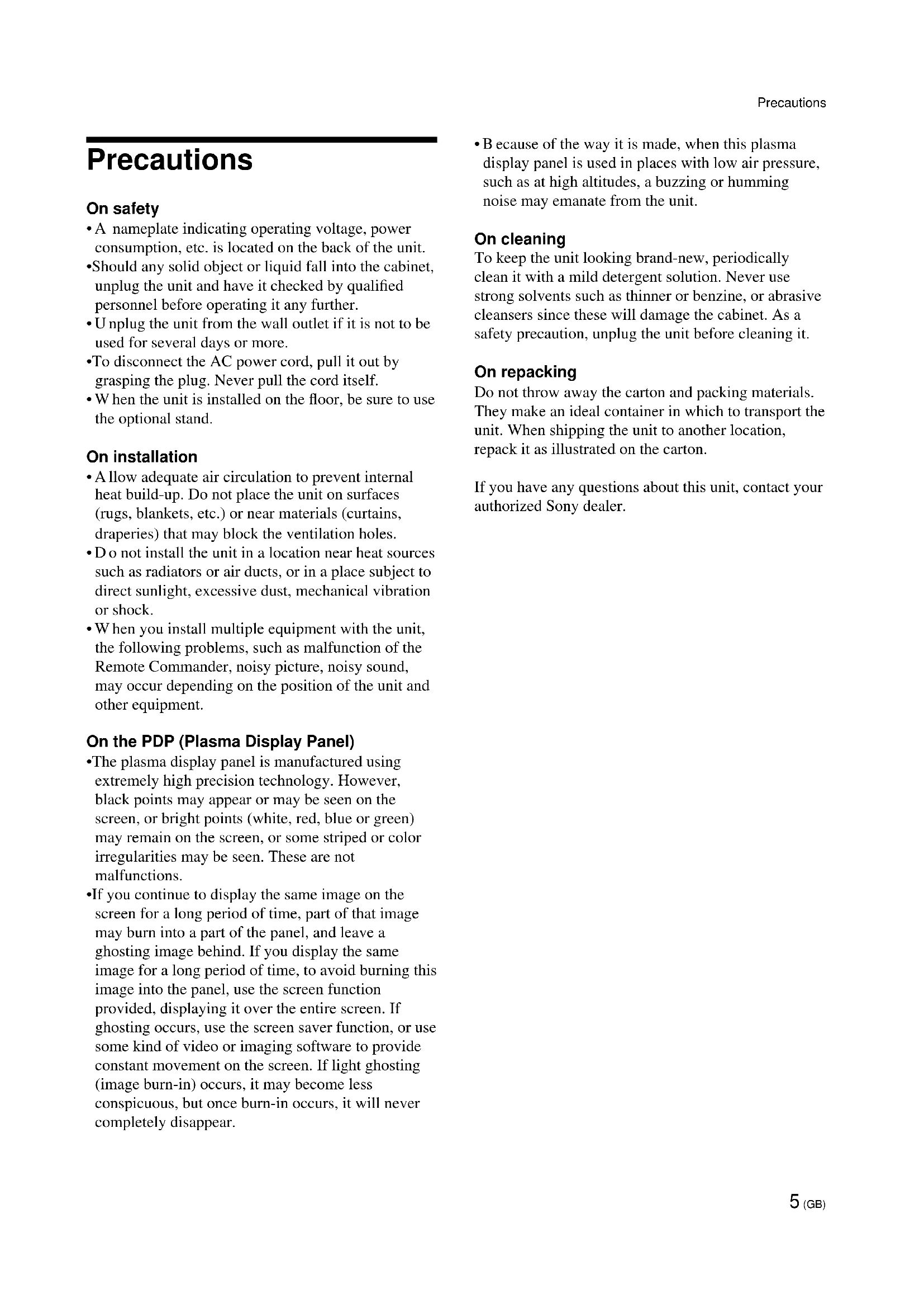
Front / Rear / Right Side
Front
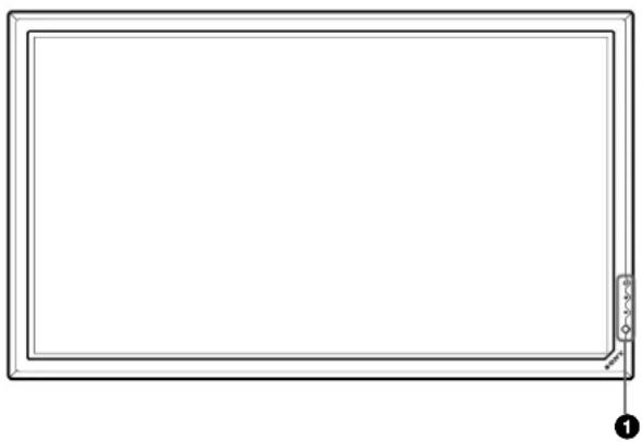
Rear
The shaded areas shown in the illustration above are all ventilation holes.
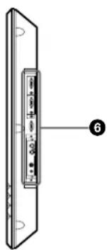
Right side
(standby) switch / indicator section
For details on the (standby) switch / indicator section, see " (standby) Switch / Indicator Section" on page 8 (GB).
Control button section
For details on the control button section, see "Control Button Section (Rear)" on page 8 (GB).
Carrying handles
AC IN socket
Connect the supplied AC power cord to this socket and to a wall outlet. Once you connect the AC power cord, the STANDBY indicator lights up in red and the display turns to the standby mode.
Stand installation hooks
Use these hooks to install the stand (not supplied).
Connector panel
For details on the connector panel, see "Connector Panel" on page 9 (GB).
(standby) Switch / Indicator Section
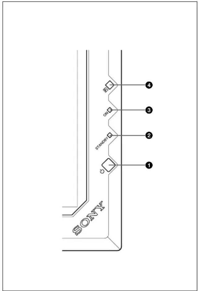
(standby) switch
Press to turn on the display unit. Press again to go back to the standby mode.
STANDBY indicator
Lights up in red in the standby mode.
When the STANDBY indicator flashes, see "Self-diagnosis Function" on page 44 (GB).
ON indicator
Lights up in green when the display unit is turned on.
Remote control detector
Receives the signal from the Remote Commander.
Control Button Section (Rear)
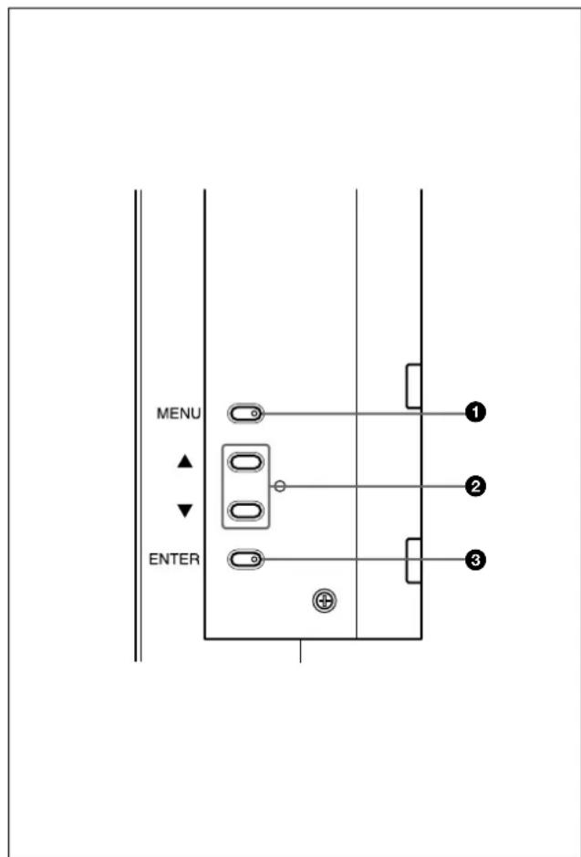
1 MENU button
Press to make the menu appear. When the menu appears on the display screen, press to return to the previous menu level. To clear the menu, press this button repeatedly until the menu disappears.
/ buttons
Press to move the cursor () to an item or to adjust a value in a menu.
③ ENTER button
Press to select the desired item from the menu displayed.
Connector Panel
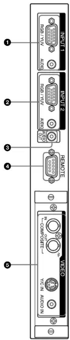
INPUT1 connectors
RGB/YUV (D-sub 15-pin): Connects to the RGB signal or component (YUV) signal output of a computer or a piece of video equipment. This display also accepts an HD analog component (Y / P_B / P_R) signal. See "Pin assignment" on page 48 (GB) when inputting a component signal.
AUDIO (Stereo minijack): Inputs an audio signal. Connects to the audio output of a computer or a piece of video equipment.
INPUT2 connectors
RGB/YUV (D-sub 15-pin): Connects to the RGB signal or component (YUV) signal output of a computer or a piece of video equipment. This display also accepts an HD analog component (Y / P_B / P_R) signal. See "Pin assignment" on page 48 (GB) when inputting a component signal.
AUDIO (Stereo minijack): Inputs an audio signal. Connects to the audio output of a computer or a piece of video equipment.
AUDIO OUT jack (Stereo minijack)
From among the audio signals input at the audio input jacks, outputs the audio signal shown on the display panel.
REMOTE (RS-232C) connector (D-sub 9-pin)
This connector allows remote control of the display using the RS-232C protocol. For details, contact your authorized Sony dealer.
VIDEO connectors
The PFM-42B1E/42B2E are not equipped with VIDEO connectors. For the PFM-42B1E/42B2E, composite video and Y/C input can be input to the display when the BKM-B10 video input adaptor or BKM-B13 video input & control S adaptor (not supplied) is installed in the display.
COMPOSITE IN (BNC-type): Connects to the composite video signal output of a piece of video equipment.
COMPOSITE OUT (BNC-type): Connects to the composite video signal input of a piece of video equipment.
Y/C IN (Mini DIN 4-pin): Connects to the Y/C signal output of a piece of video equipment.
AUDIO IN (Stereo minijack): Inputs an audio signal. Connects to the audio output of a piece of video equipment.
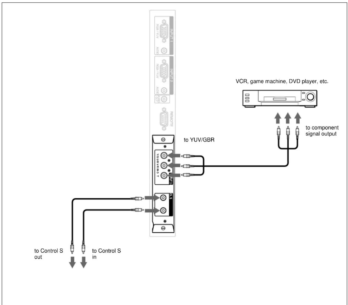
Component Input Adaptor (with Control S) BKM-B12 (Not supplied)
The VIDEO connectors are Slot-in connectors. You can replace the VIDEO connectors with the Component Input Adaptor (with Control S) BKM-B12.
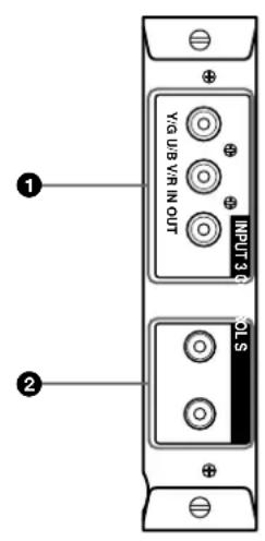
INPUT3 (RGB/YUV signal input) connectors RGB/YUV (RGB/YUV signal input) connector (Phono jack): Connects to the analog RGB signal output connector (image device) or to the Component (YUV) signal output connector. Yo can also input the HD analog component (Y / P_B PR) signals to this connector.
CONTROL S IN/OUT (Control S signal input/output) connector (Minijack)
CONTROL S IN/OUT (Control S signal input/output) connector (Minijack)
You can connect the CONTROL S connector on a video device or display to this connector, you can control multiple devices from one Remote Commander. Connect the CONTROL S OUT connector on this adaptor to the CONTROL S IN connector on the other device.
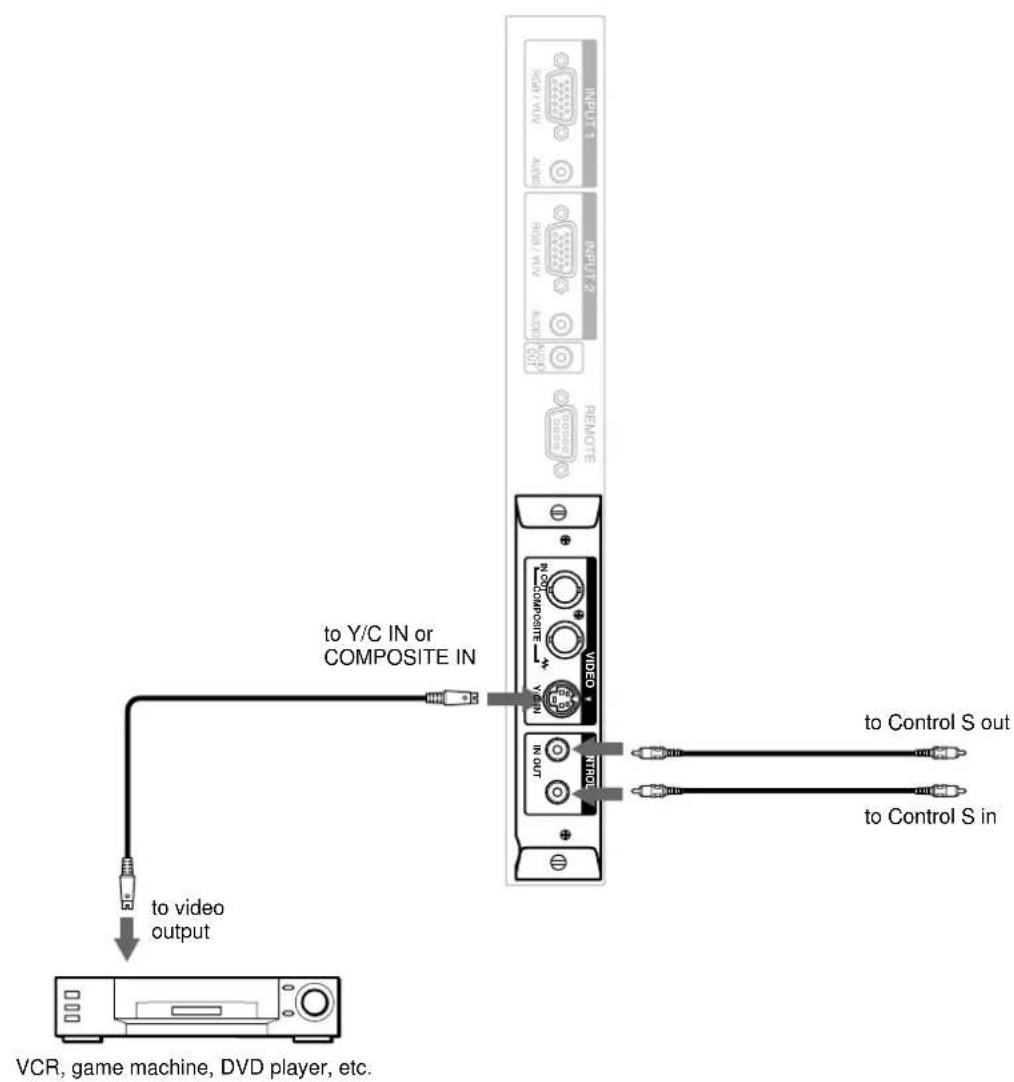
Video Input & Control S Adaptor BKM-B13 (Not supplied)
The VIDEO connectors are Slot-in connectors. You can replace the VIDEO connectors with the VIDEO Input & Control S Adaptor BKM-B13.
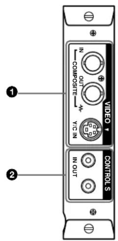
VIDEO Connectors
COMPOSITE IN (Video Input) connector (BNC): Connects to the composite signal output connector on the video device.
COMPOSITE OUT (Video Output) connector (BNC): Connects to the composite signal input connector on the video device.
Y/C IN (Video Input) connector (Mini-DIN 4-pin): Connects to the Y/C output connector on the video device.
CONTROL S IN/OUT (Control S signal input/output) connector (Minijack)
You can connect the CONTROL S connector on a video device or display to this connector, you can control multiple devices from one Remote Commander. Connect the CONTROL S OUT connector on this adaptor to the CONTROL S IN connector on the other device.
Network Adaptor BKM-B30NW (Not supplied)
The VIDEO connectors are Slot-in connectors. You can replace the VIDEO connectors with the Network Adaptor BKM-B30NW.
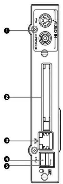
VIDEO IN connector
Y/C connector (Mini DIN 4 pin): Connect to the Y/ C output connector of an image device.
COMPOSITE connector (Pinjack): Connect to the composite output connector of an image device.
PC card slot
Install a LAN card or PC memory card as needed.
Ethernet connector
Connect to another networked computer with a 10/ 100BASE-T LAN cable.
4 Keyboard connector
Connect a USB keyboard.
Mouse connector
Connect a USB mouse.
Remote Commander RM-42B
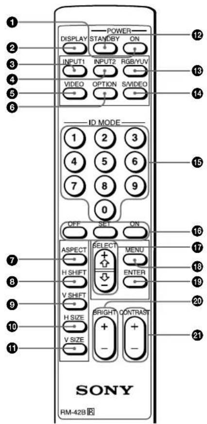
POWER ON switch
Press to turn on the display.
② DISPLAY button
Displays the input signal information and the time at the top of the display panel. Press again to clear it.
INPUT1 button
Selects the signal input from the INPUT1 connectors.
4 INPUT2 button
Selects the signal input from the INPUT2 connectors.
⑤VIDEO button
Selects the signal input from the COMPOSITE IN connector or Y/C IN connector from among the VIDEO connectors.
OPTION button
Selects the signal input from the optional adaptor when you install it in the unit.
ASPECT button
Changes the aspect ratio of the picture.
H SHIFT button
Adjusts the horizontal centering. Press this button and then adjust the horizontal centering with the SELECT + / - button 17.
VSHIFT button
Adjusts the vertical centering. Press this button and then adjust the vertical centering with the SELECT + / - button 17.
H SIZE button
Adjusts the horizontal picture size. Press this button and then adjust the horizontal picture size with the SELECT + / - button 17.
VSIZEbutton
Adjusts the vertical picture size. Press this button and then adjust the vertical picture size with the SELECT + / - button 17.
STANDBY button
Press to turn the display to the standby mode.
RGB/YUV button
Press to select the format matching that of the input signal connected to the INPUT1 or INPUT2 connector. Each press toggles between RGB and YUV.
S/VIDEO button
Press to select the signal input from the COMPOSITE IN connector or Y/C IN connector from among the VIDEO connectors. Each press toggles between COMPOSITE IN and Y/C IN.
15 Number buttons
Press to enter the index number.
ID MODE (ON/SET/OFF) buttons
Press the ON button to make an index number appear on the screen. Then enter the index number of the display you want to operate using the number buttons
15 and press the SET button. After you finish the operation, press the OFF button to return from the ID mode to the normal mode.
For details about the index number, see "Operating a Specific Display With the Remote Commander" on page 44 (GB).
SELECT +/-- button
Press to move the cursor () to an item or to adjust a value in a menu.
18 MENU button
Press to make the menu appear. When the menu appears on the display panel, press to return to the previous menu level. To clear the menu, press this button repeatedly until the menu disappears.
19 ENTER button
Press to select the desired item in a menu.
20 BRIGHT + / - button
Adjusts the brightness.
21 CONTRAST + / - button
Adjusts the contrast.
Installing batteries
Insert two size AA (R6) batteries in correct polarity.
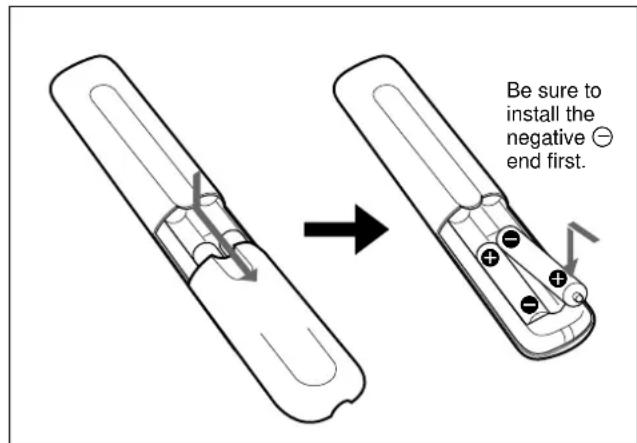
- In normal operation, batteries will last up to half a year. If the Remote Commander does not operate properly, the batteries might be exhausted sooner. Replace them with new ones.
- To avoid damage from possible battery leakage, remove the batteries if you do not plan to use the Remote Commander for a fairly long time.
When the Remote Commander does not work
Check that the STANDBY indicator lights up and the REMOTE MODE in the REMOTE menu is not set to OFF. The Remote Commander operates the display only when both of the two conditions below are met.
The display is turned on, or it is in the standby mode.
- The REMOTE MODE in the REMOTE menu is set to TV or to PJ.
For details about the REMOTE MODE, see "REMOTE menu" on page 21 (GB).
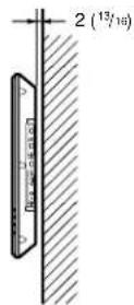
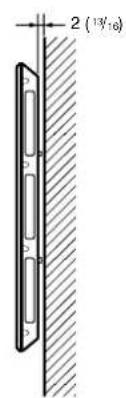
Caution
- When you use the display, make sure there is more space around the display than that shown in the figure below. This will allow for proper ventilation.
The ambient temperature must be 0^ to +35^ (32^ to 95^) - U see the SU-42B display stand (not supplied) as a stand.
The wall should be reinforced to bear at least five times the weight of the display (PFM-42B1/42B1E: approx. 29.4kg /PFM-42B2/42B2E: approx. 28.4kg ) plus the wall bracket you are planning to use. - Regarding installation of hardware such as brackets, screws, and bolts, we cannot specify what to use because actual installation is up to the authorized local dealers. For installation, consult with qualified Sony personnel.
When using the stand (not supplied)
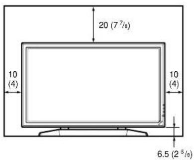
Front
Side
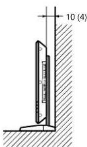
Units: cm (inches)
When mounting the display horizontally Front
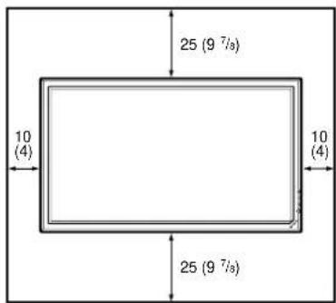
Side
Units: cm (inches)
When mounting the display vertically Front
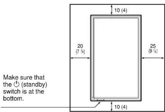
Side
Units: cm (inches)
Connections
Connecting the AC Power Cord
1 Plug the AC power cord into the AC IN socket. Then, attach the AC plug holder (supplied) to the AC power cord.
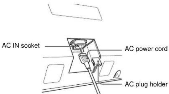
2 Slide the AC plug holder over the cord until it connects to the AC IN socket cover.
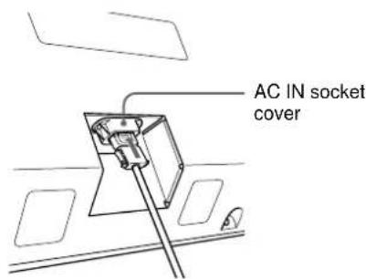
To remove the AC power cord
After squeezing the AC plug holder and freeing it, grasp the plug and pull out the AC power cord.
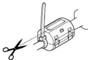
Attaching the ferrite core (PFM42B2/42B2E only)
1 Attach the ferrite cores to both ends of the AC power cord and close the ferrite cores until they click.

2 Wind the stopper round the cord so that the ferrite cores do not slide.
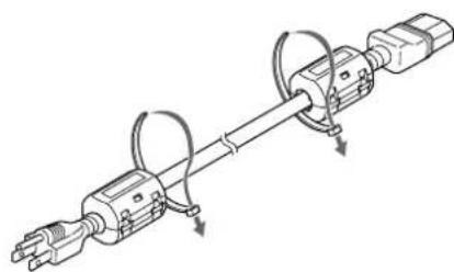
3 Tighten the stopper and cut the surplus.
Connection Example
Before you start
- First make sure that the power to each piece of equipment is turned off.
- Use connecting cables suitable for the equipment to be connected.
The cable connectors should be fully inserted into the jacks. A loose connection may cause hum and other noise. - To disconnect the cable, pull it out by grasping the plug. Never pull the cable itself.
- Refer to the instruction manual of the equipment to be connected.
- Insert the plug securely into the AC IN socket.
- Use one of the two AC plug holders (supplied) that will securely hold the AC plug.
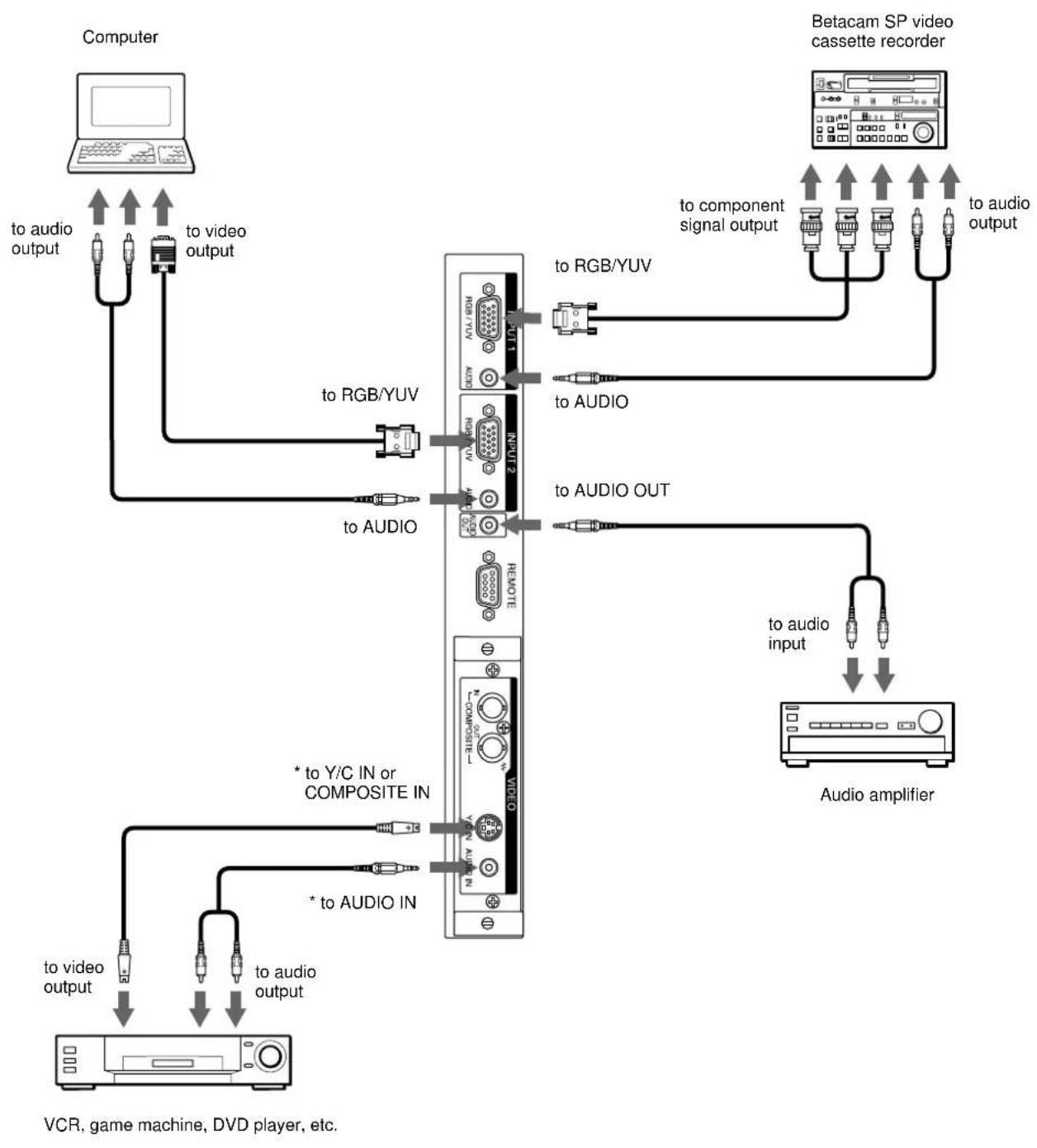
* For the PFM-42B1E/42B2E, this can be used when the BKM-B10 video input adaptor (not supplied) is installed in the display unit.
Connection Example: The Component Input Adaptor (with Control S) BKM-B12 (Not supplied) has been installed.
The following shows the connection example where the Component Input Adaptor (with Control S) BKM-B12 (Not supplied) has been installed.
Connection Example: The Video Input & Control S Adaptor BKM-B13 (Not supplied) has been installed.
The following shows a connection example where the Video Input & Control S Adaptor BKM-B13 (Not supplied) has been installed.
For a connection example of the BKM-B30NW network adaptor (Not supplied), see the BKM-B30NW instruction manual.
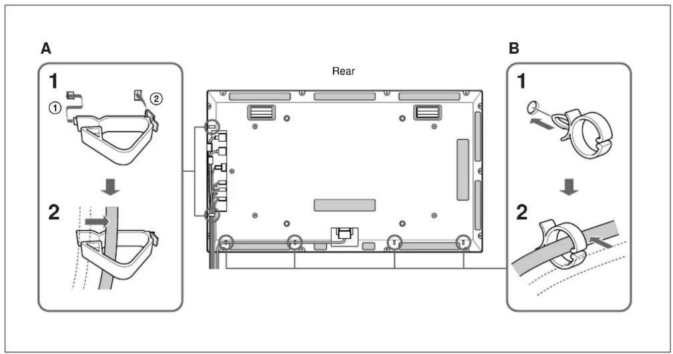
Using the cable holders
You can fasten the connecting cables and AC power cord with the cable holders A (× 2) and B (× 4) . Attach the cable holders A and B as the illustration below.
Using On-screen Menus
Operating Through Menus
Menu operating buttons
Use the buttons on the display unit or the Remote Commander for menu operations.
Remote Commander


Control button section

The buttons on the control button section are used for purposes of explanation in this operating instructions.
The SELECT + / - button on the Remote
Commander has the same functions as the /
buttons on the control button section.
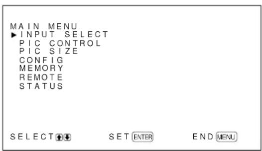
Configuration of the menu
To select the language used in the menu, see page 35 (GB).
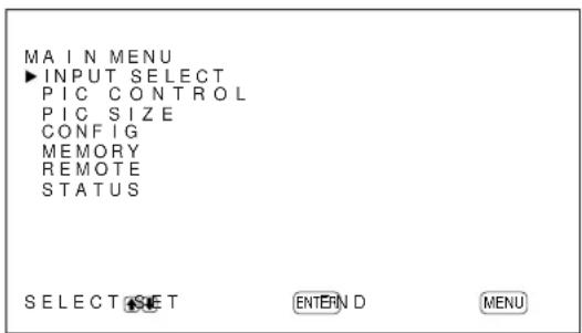
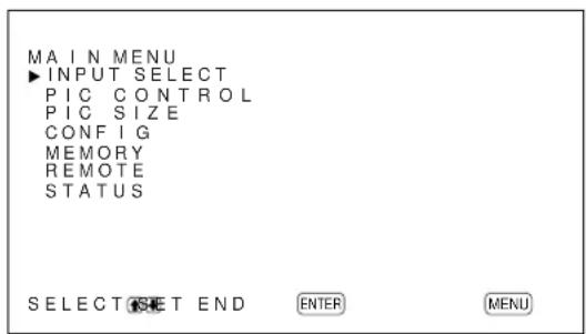
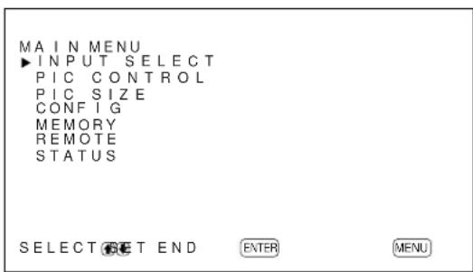
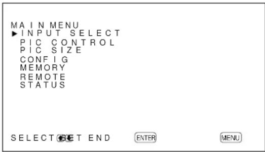
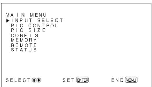
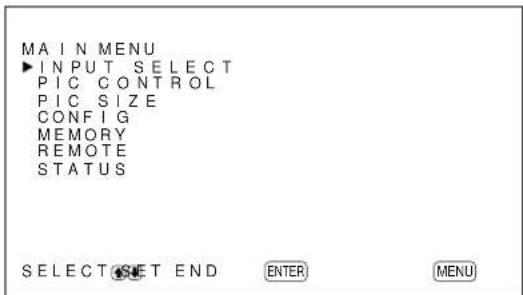
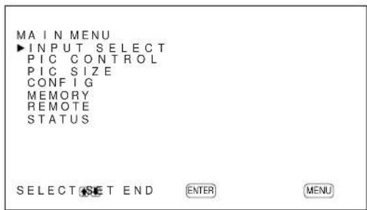
1 Press MENU.
The main menu appears on the display panel.
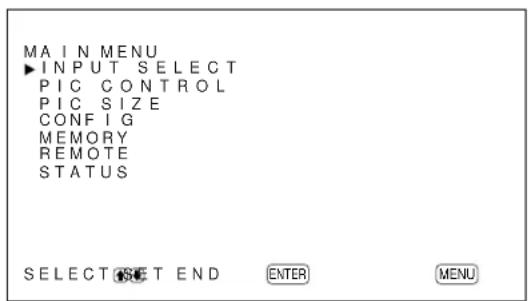
2 Press / to move the cursor (▶) and press ENTER to select a menu.
The selected menu appears on the display panel.
3 Press / to move the cursor (▶) and press ENTER to select an item.
The menu for the selected item appears on the display panel.
4 Press / to adjust or select the setting and press ENTER to set.
The setting is registered and the menu returns to the previous menu.
To return to the normal screen, press the MENU button repeatedly until the menu disappears.
Menu Guide
Note
"---" appears next to an item when its function is not available. The availability depends on the types of input signal.
PIC CONTROL menu
This menu is used for adjusting the picture.
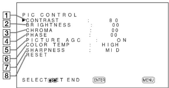
1 CONTRAST
Press to increase the contrast and press to decrease it.
2 BRIGHTNESS
Press to make the picture brighter and press to make it darker.
3 CHROMA
Press to increase color saturation and press to decrease it.
4PHASE
Press to make the overall picture greenish and press to make it purplish.
5 PICTURE AGC
Select ON to automatically increase the brightness when a low brightness signal is input.
This function works only for VIDEO input or 15kHz YUV input.
6 COLOR TEMP
Changes the color temperature.
For details, see "COLOR TEMP" on page 27 (GB).
7 SHARPNESS
Changes the outline correction level using the following three levels (HIGH, MID or LOW).
For details, see "SHARPNESS" on page 28 (GB).
8 RESET
Restores the factory settings in the PIC CONTROL menu items 1 to 7.
For details on using the reset function, see "Restoring the PIC CONTROL Menu Items to Their Original Settings" on page 28 (GB).
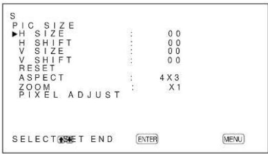
PIC SIZE menu
This menu is used for resizing and positioning the picture.
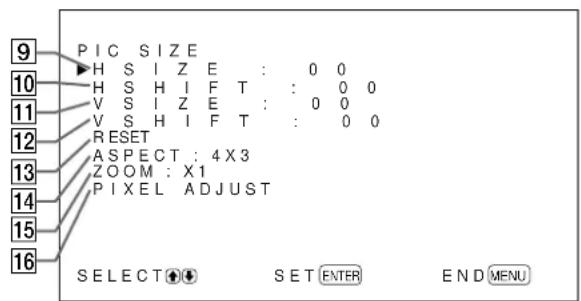
9 H SIZE
Adjusts the horizontal picture size. Press to enlarge the horizontal size and press to diminish it.
10 H SHIFT
Adjusts the horizontal centering. Press to move the picture to the right and press to move it to the left.
VSIZE
Adjusts the vertical picture size. Press to enlarge the vertical size and press to diminish it.
12 V SHIFT
Adjusts the vertical centering. Press to move the picture up and press to move it down.
13 RESET
Restores the factory settings in PIC SIZE menu items
9 to 12.
For details on using the reset function, see "Restoring the Original Picture Size and Position" on page 30 (GB).
14 ASPECT
Changes the aspect ratio of the picture.
For details, see "Changing the Aspect Ratio" on page 31 (GB).
15 ZOOM
Enlarges the image (in order) to double (× 2) , triple (× 3) and quadruple (× 4) .
Note
When you set ASPECT to W ZOOM or LB ZOOM, "---" appears and you cannot set ZOOM to × 2 , × 3 or × 4 .
16PIXELADJUST
Adjusts the dot phase and the total number of horizontal pixels when you see noise on the edges of the characters and the vertical lines.
For details, see "Adjusting the Pixels" on page 32 (GB).
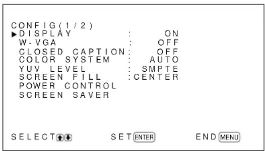
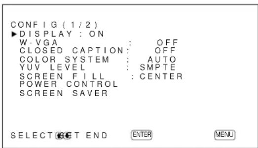
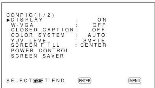
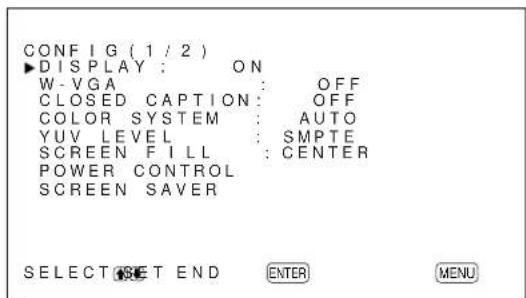
CONFIG menu
This menu is used for adjusting the signal or selecting the language. This menu consists of two pages;
CONFIG (1/2), CONFIG (2/2). To toggle between pages, press the / buttons repeatedly until the other page appears.
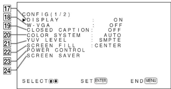
PFM-42B1/42B1E: "YUV LEVEL" is not displayed.
PFM-42B1/42B1E: "SERIAL REMOTE" is not displayed. If you have installed the Network Adaptor (BKM-B30NW), the "NETWORK ADAPTOR" is added but it does not appear in the PFM-42B1/42B1E.
17 DISPLAY
Select ON to display the input signal information for about five seconds at the top of the display panel when the power is turned on or when switching the input signal.
18 W-VGA
Select ON to input the W-VGA (852× 480) signal.
When you set this item to ON, the VGA input signal is determined to be 852 × 480 . Otherwise, the VGA input signal is determined to be 640 × 480 .
19 CLOSED CAPTION
Displays closed captions.
For details, see "Displaying closed captions" on page 24 (GB).
20 COLOR SYSTEM
Selects the input signal.
AUTO: to display NTSC, PAL or SECAM signals
443NT: to display NTSC4.43 signals
PAL60: to display PAL60 signals
PAL-M: to display PAL-M signals
21 YUV LEVEL (PFM-42B2/42B2E only)
Select the component signal level.
SMPTE: SMPTE level signal
BETA: BETACAM level signal
22 SCREEN FILL
Selects the point of origin for resizing the picture.
CENTER: Sets the point of origin at the center of the display panel.
CORNER: Sets the point of origin at the upper-left corner of the display panel.
23 POWER CONTROL
Sets the length of time until the system goes into the power saving mode.
For details, see "Controlling Power On/Off Automatically (Power Control Function)" on page 38 (GB).
24 SCREENSAVER
Enables a screen saver to reduce afterimage or ghosting.
For details, see "Reducing Afterimage/Ghosting (Screen Saver Function)" on page 36 (GB).
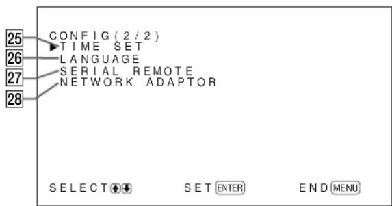
25 TIME SET
Sets the time.
For details, see "Adjusting the time" on page 24 (GB).
26 LANGUAGE
Selects the on-screen language (English, German, French, Italian, Spanish or Japanese).
For details, see "Selecting the On-screen Language" on page 35 (GB).
27 SERIAL REMOTE (PFM-42B2/42B2E only)
Setting the Serial Remote.
For details, see "Setting the SERIAL REMOTE" on page 42 (GB).
28 NETWORK ADAPTOR (PFM-42B2/42B2E only)
Setting the Network Adaptor.
For details, see "Setting the NETWORK ADAPTOR" on page 43 (GB).
MEMORY menu
This menu is used for saving or recalling the settings in the PIC CONTROL and PIC SIZE menus.
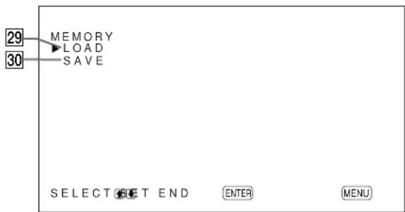
For details, see "Using the Memory Function" on page 33 (GB).
29 LOAD
Recalls the preset settings.
30 SAVE
Saves the settings.
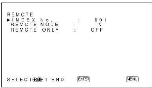
REMOTE menu
This menu is used for remote control settings.
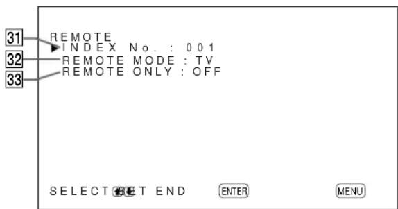
31 INDEX No.
Sets the index number of the display.
Note
When you set the number, use the buttons on the display unit.
For details about the index number, see "Operating a Specific Display With the Remote Commander" on page 44 (GB).
32 REMOTE MODE
Selects the Remote Commander mode.
TV: The Sony display's or the TV's commander
PJ: The Sony projector's commander
OFF: Disables the remote control.
Note
When you change the Remote Commander mode, use the buttons on the display unit. You cannot change the Remote Commander mode with the Remote Commander.
For details, see "Using Other Remote Commander Models" on page 46 (GB).
33 REMOTE ONLY
Select ON to disable the control buttons on the display unit. The display can only be controlled with the Remote Commander.
To cancel the REMOTE ONLY mode, set REMOTE ONLY to OFF with the Remote Commander, or press the MENU button while pressing the (standby) switch on the display unit. The display turns to the standby mode and the REMOTE ONLY mode is cancelled.
The setting in this item is still retained when the AC power cord is disconnected or when you turn the display on/off with the Remote Commander.
STATUS menu
This menu is used for displaying the internal status of the display unit.
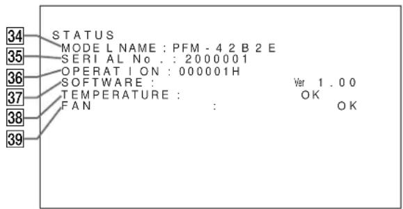
34 MODEL NAME
Indicates the model name.
The description in this section is based on the PFM-42B2E.
35 SERIAL No.
Indicates the serial number.
36 OPERATION
Indicates the total number of hours of operation.
Note
The standby mode is not counted as part of the OPERATION time.
37 SOFTWARE
Indicates the system software version.
38 TEMPERATURE
Indicates whether the internal temperature of the display unit is normal.
OK: Normal
NG: Unusual
When the internal temperature is unusual, NG is displayed and the item flashes in red. The STANDBY indicator on the (standby) switch / indicator section also flashes.
Note
The "TEMPERATURE NG" message may appear when the ventilation holes are blocked or the display unit is installed in a poorly ventilated location. In this case, check that the ventilation holes are not blocked and install the display unit in a well ventilated location. If the message is still shown, contact your authorized Sony dealer.
When the STANDBY indicator flashes or NG is indicated, see "Self-diagnosis Function" on page 44 (GB).
39 FAN
Cooling fans are built into this display unit. This item indicates whether the cooling fans work properly.
OK: Normal
NG: Unusual
When the cooling fans are not working normally, NG is displayed and the item flashes in red. The STANDBY indicator on the (standby) switch / indicator section also flashes.
Notes
- When the "FAN NG" message appears, contact your authorized Sony dealer.
When the STANDBY indicator flashes or NG is indicated, see "Self-diagnosis Function" on page 44 (GB).
- The cooling fans detect the display unit's internal temperature and control the fan rotation. If the ambient temperature is high, the fan speed increases and the fan noise will be louder.
Watching the Picture
Before you start
- Turn on the display.
- Turn on the connected equipment and play a video source.
- To display the input signal information on the screen when turning on the power or switching the input signal, set "DISPLAY" in the CONFIG (1/2) menu to ON.
To select the on-screen language used in the menu, see page 35 (GB).
Switching the Input Signal
1 Press MENU.
The main menu appears on the display panel.
2 Press / to move the cursor () to "INPUT SELECT" and press ENTER.
The currently selected input signal and INPUT SELECT menu appear on the display panel.
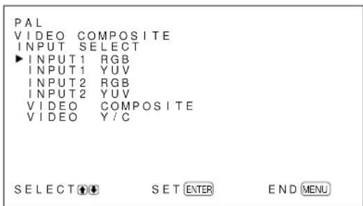
3 Press / to move the cursor () to the input source to be displayed and press ENTER.
INPUT1 RGB: Selects the audio and video signal input from the INPUT1 connectors when the input signal is an RGB signal.
INPUT1 YUV: Selects the audio and video signal input from the INPUT1 connectors when the input signal is a component signal.
INPUT2 RGB: Selects the audio and video signal input from the INPUT2 connectors when the input signal is an RGB signal.
INPUT2 YUV: Selects the audio and video signal input from the INPUT2 connectors when the input signal is a component signal.
VIDEO COMPOSITE: Selects the audio and video signal input from the COMPOSITE IN connector and AUDIO IN jack among the VIDEO connectors.
VIDEO Y/C: Selects the audio and video signal input from the Y/C IN connector and AUDIO IN jack among the VIDEO connectors.
(For the PFM-42B1E/42B2E,VIDEO
COMPOSITE and VIDEO Y/C only appear when the BKM-B10 video input adaptor or BKM-B13 video input & control S adaptor (not supplied) is installed.)
INPUT3 RGB: Selects the input signal (RGB signal) from the device connected to the INPUT 3 connector. (Only when the BKM-B12 component adaptor is installed.)
INPUT3 YUV: Selects the input signal (Component signal) from the device connected to the INPUT3 connector. (Only when the BKM-B12 component adaptor is installed.)
INPUT3 PC: Selects the signal from the BKM-B30NW network adaptor installed in the VIDEO connector unit. (Only when the BKM-B30NW network adaptor is installed.)
The selected input signal appears on the display panel.
You can also switch the input signal using the Remote Commander.
Note
We recommend input source video equipment equipped with a TBC (time base corrector). If the display receives a signal without TBC, the picture may disappear due to disturbance of the sync signal.
Switching the Display Mode
Displaying closed captions
1 Press MENU.
The main menu appears on the display panel.
2 Press / to move the cursor (▶) to "CONFIG" and press ENTER.
The CONFIG (1/2) menu appears on the display panel.
3 Press / to move the cursor () to "CLOSED CAPTION" and press ENTER.
The following menu appears on the display panel.
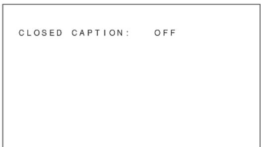
4 Select the caption type with / .
OFF: The caption is not displayed.
CAPT1: Displays caption1 over the picture.
CAPT2: Displays caption2 over the picture.
TEXT1: Displays caption1 against a black background.
TEXT2: Displays caption2 against a black background.
5 Press MENU.
The menu returns to the CONFIG (1/2) menu.
Adjusting the time
1 In the CONFIG (2/2) menu, press / to move the cursor () to "TIME SET" and press ENTER. The following menu appears on the display panel.
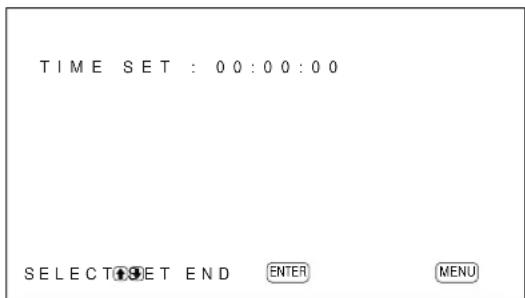
2 Press ENTER.
The background of the hour is displayed in cyan.
3 Adjust the hour with / and press ENTER. The setting for the hour is entered and the background of the minute is displayed in cyan.
4 Similarly, adjust the minute and press ENTER. The setting for the minute is entered and the second is reset to 00.
To display the time
Press the DISPLAY button on the Remote Commander. The time is shown in the upper-right corner of the display.
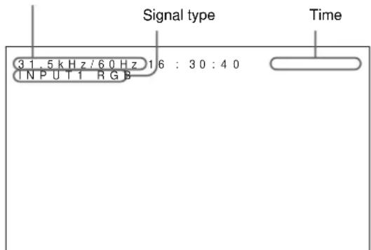
Input Signal and Display Status Information
Input signal and display status information is appears on the display panel for about five seconds when the power is turned on or when switching the input signal. To disable this function, follow the steps below.
1 In the CONFIG (1/2) menu, press / to move the cursor () to "DISPLAY" and press ENTER. The following menu appears on the display panel.

2 Press / to set DISPLAY to OFF and press ENTER. The DISPLAY function is disabled.
To display the information
Set DISPLAY to ON in step 2 above. The factory default is ON.
Note
You can display the input signal information and the time anytime by pressing the DISPLAY button on the Remote Commander, regardless of the above setting.
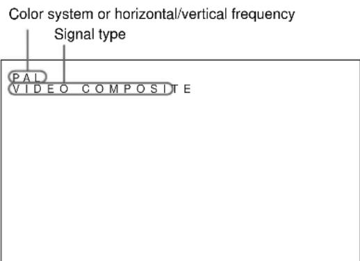
The input signal information list
Color system or horizontal/vertical frequency
| Preset input signals | |||
| Signal name | Color system or horizontal/vertical frequency | ||
| Computer signals | |||
| 1 | VGAa)-1 (VGA 350) 31.5kHz | Hz 70.1Hz | |
| 2 | 640×350@85Hz (VESAb) STD) | 37.9kHz 85.1Hz | |
| 3 | 640×400@85Hz (VESA STD) | 7.9kHz 85.1Hz | |
| 4 | 640×480@60Hz (VESA STD) | 31.5kHz 59.9Hz | |
| 5 | Macc) 13" | 35.0kHz 66.7Hz | |
| 6 | 640×480@72Hz (VESA STD) | 7.9kHz 72.8Hz | |
| 7 | 640×480@75Hz (VESA STD) | 37.5kHz 75.0Hz | |
| 8 | 640×480@85Hz (VESA STD) | 3.3kHz 85.0Hz | |
| 9 | 852×480@60Hz (I -O DATA)d) | 31.7kHz 60.0Hz | |
| 10 | VGA (VGA TEXT) 31.5kHz 70.1Hz | ||
| 11 | 720×400@85Hz (VESA STD) | 37.9kHz 85.0Hz | |
| 12 | 800×600@56Hz (VESA STD) | 35.2kHz 56.3Hz | |
| 13 | 800×600@60Hz (VESA STD) | 37.9kHz 60.3Hz | |
| 14 | 800×600@72Hz (VESA STD) | 48.1kHz 72.2Hz | |
| 15 | 800×600@75Hz (VESA STD) | 6.9kHz 75.0Hz | |
| 16 | 800×600@85Hz (VESA STD) | 3.7kHz 85.1Hz | |
| 17 | Mac 16 " | 49.7kHz 74.6Hz | |
| 18 | 1024×768@60Hz (VESA STD) | 48.4kHz | 60.0Hz |
| 19 | 1024×768@70Hz (VESA STD) | 56.5kHz | 70.1Hz |
| 20 | 1024×768@75Hz (VESA STD) | 60.0kHz | 75.0Hz |
| 21 | 1024×768@85Hz (VESA STD) | 68.7kHz | 85.0Hz |
| 22 | 1152×864@75Hz (VESA STD) | 67.5kHz | 75.0Hz |
| 23 | Mac 21 " | 68.7kHz 75.1Hz | |
| 24 | 1280×960@60Hz (VESA STD) | 60.0kHz | 60.0Hz |
| 25 | 1280×960@85Hz (VESA STD) | 85.9kHz | 85.0Hz |
| 26 | 1280×1024@60Hz (VESA STD) | 64.0kHz 60.0Hz | |
| 27 | 1280×1024@75Hz (VESA STD) | 80.0kHz 75.0Hz | |
| 28 | 1280×1024@85Hz (VESA STD) | 91.1kHz 85.0Hz | |
| 29 | 1600×1200@60Hz (VESA STD) | 75.0kHz 60.0Hz | |
| 30 | 856×480@60Hz (Matrox) e) | 30.2kHz 60.0Hz | |
| 31 | 856×480@59.6Hz (Matrox) e) | 30.1kHz 59.6Hz | |
| 32 | 856×480@60.1Hz (Matrox) e) | 30.1kHz 60.1Hz | |
| SDTV/HDTV | |||
| 1 | PAL PAL | ||
| 2 | NTSC | NTSC | |
| 3 | SECAM | SECAM | |
| 4 | NTSC4.43 | NTSC/4.43 | |
| 5 | PAL60 | PAL/60 | |
| 6 | PAL-M | PAL-M | |
| 7 | 575/50i | 575/50i | |
| 8 | 480/60i | 480/60i | |
| 9 | 1080/24psf | 1080/48i | |
| 10 | 1080/50i | 1080/50i | |
| 11 | 576/50p | 576/50P | |
| 12 | 480/60p | 480/60P | |
| 13 | 1080/60i | 1080/60i | |
| 14 | 720/60p | 720/60P | |
a) VGA is a registered trademark of International Business Machines Corporation, U.S.A.
b) VESA is a registered trademark of the Video Electronics Standards Association.
c) Mac (Macintosh) is a registered trademark of Apple Computer, Inc.
d) This item is only available when you use a graphic accelerator board manufactured by I-O DATA DEVICE, INC.
e) This item is only available when you use a graphics card manufactured by Matrox Graphics Inc.
Notes
- When inputting an HDTV signal, input the tri-level sync signal to the 2nd pin of the INPUT1 or INPUT2 (D-sub 15-pin) connector.
- When inputting a computer signal at the resolution shown in item No. 29, set H SIZE, H SHIFT, V SIZE and V SHIFT to the standard (00) and set ZOOM to × 1 in the PIC SIZE menu, or the picture might oscillate.
- If the image color is too light after inputting the DVD signal in the PFM-42B1/42B1E, adjust the color in the "CHROMA" setting in the PIC CONTROL menu. In the PFM-42B2/42B2E, select "SMPTE" in YUV LEVEL in the CONFIG menu.
- For 480/60p , input it using a YUV signal. If you input an RGB signal, the system will determine the frequency to be a VGA signal, it will display at 31.5kHz / 59.9Hz , the screen phase will be off, and compared to YUV input, the resolution will be reduced. To address problems with screen phase, use the H SHIFT and V SHIFT items on the Signal Adjustment menu, or use the H SHIFT, V SHIFT and SELECT buttons on the RM-42B Remote Commander to make the necessary adjustments.
- When inputting a DTV signal (No.7 to No.14), input it using a YUV signal.
Actual on-screen display of the unit's status
| On-screen display | Significance |
| 31.5kHz / 59.9Hz (e.g.) | The selected input signal is computer RGB. |
| 480 / 60I (e.g.) | The selected input signal is component video. |
| NTSC (e.g.) The selected input signal is NTSC. | |
| OTHERS | The input signal is out of the capture range. |
| NO SYNC | There is no input signal. |
| INPUT1 RGB | The signal mode of INPUT1 is set to RGB. |
| INPUT1 YUV | The signal mode of INPUT1 is set to component video. |
| VIDEO COMPOSITE | Composite video input is selected for VIDEO. |
| VIDEO Y/C | Y/C video input is selected for VIDEO. |
Adjusting the Picture
While watching the picture, you can adjust contrast, brightness, chroma, phase, and so on, to suit your taste. The adjustments can be carried out for each input signal separately. You can also store the adjusted levels in memory.
Adjusting the Contrast, Brightness, Chroma, and Phase, etc.
Press MENU so that the main menu appears on the display panel and select "CONTRAST", "BRIGHTNESS", "CHROMA", "PHASE", "PICTURE AGC", "COLOR TEMP" or "SHARPNESS" from the PIC CONTROL menu with / .
CONTRAST
Select "CONTRAST" with / and press ENTER. Adjust the contrast with / in the range from MIN (0) to MAX (+100).
to increase picture contrast
: to decrease picture contrast
BRIGHTNESS
Select "BRIGHTNESS" with / and press ENTER. Adjust the brightness with / in the range for MIN (-50) to MAX (+50).
to make the picture brighter
: to make the picture darker
CHROMA
Select "CHROMA" with / and press ENTER. Adjust the chroma with / in the range from MIN (-50) to MAX (+50).
to increase color intensity
: to decrease color intensity
PHASE
Select "PHASE" with / and press ENTER. Adjust the phase with / in the range from MIN (-50) to MAX (+50).
to make the overall picture greenish
: to make the overall picture purplish
Automatic brightness control Enhancing the image contrast
If the average brightness of the image is low, the system can automatically raise the contrast level to enhance the brightness. This function works well for displaying dark images.
Select "PICTURE AGC" with / and press ENTER. Set PICTURE AGC to ON or OFF with / .
COLOR TEMP (Color temperature)
You can also set the color temperature. You can select HIGH or LOW, or adjust each gain more precisely. Up to six adjusted color temperatures can be registered. You can rename them (up to six characters in length).
1 Select "COLOR TEMP" with / and press ENTER.
2 Select the color temperature with / and press ENTER.
HIGH: to set the color temperature to high LOW: to set the color temperature to low 1-6: to set the gain more precisely
When you select HIGH or LOW, the menu returns to the PIC CONTROL menu.
When you select "1" to "6"
When you select "1" to "6", the following menu appears on the display panel.
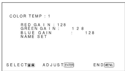
The PFM-42B1/42B1E displays "255" for each gain.
(1) Select a number to register with / and press ENTER. The cursor () appears on the display pane
(2) Press / to move the cursor (▶) to the gain item that you want to set and press ENTER. The following menu appears on the display panel.
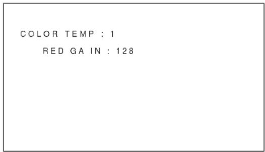
(3) Adjust the gain (0 to 255) with / and press MENU. The menu returns to the COLOR TEMP menu. The PFM-42B1/42B1E variable range is 10 to 255.
(4) Repeat steps (2) and (3) to set the other gain items and press MENU. The menu returns to the COLOR TEMP menu.
When you rename the adjusted color temperature, follow the steps below.
(5) Press / to move the cursor (▶) to "NAME SET" and press ENTER. The following menu appears on the display panel.
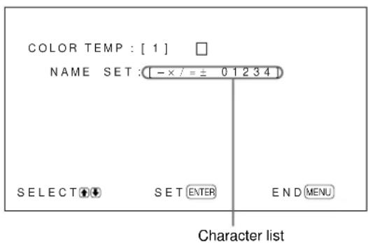
(6) Select the character to be changed with / and press ENTER. The background of a character in the character list changes to cyan.
(7) Select a character in the character list with / and press ENTER. The selected character is input.
(8) Repeat steps (6) and (7) until you finish inputting the name, then press MENU. The menu returns to the COLOR TEMP menu.
SHARPNESS
You can change the outline correction level to one of three levels (HIGH, MID or LOW).
1 Press / to move the cursor (▶) to "SHARPNESS" and press ENTER.
2 Select the outline correction level with / and press ENTER.
HIGH: sharper picture
MID: standard value
LOW: softer picture
Notes
- CHROMA and PHASE controls do not function with an RGB signal.
PHASE control does not function with a component signal.
PHASE control does not function with a PAL or SECAM color source. - Do not change the CHROMA/PHASE (NTSC only) level when the selected signal is black-and-white. Although it has no effect on the current picture, it does affect the picture of color signals such as NTSC or PAL which may be input later.
Restoring the PIC CONTROL Menu Items to Their Original Settings
1 In the PIC CONTROL menu, Press / to move the cursor (▶) to "RESET" and press ENTER. The following menu appears on the display panel.
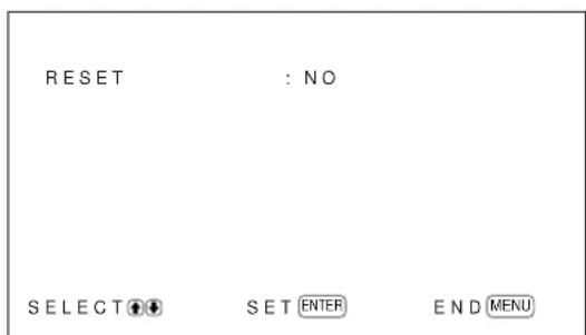
2 Press / .
"NO" changes to "YES".
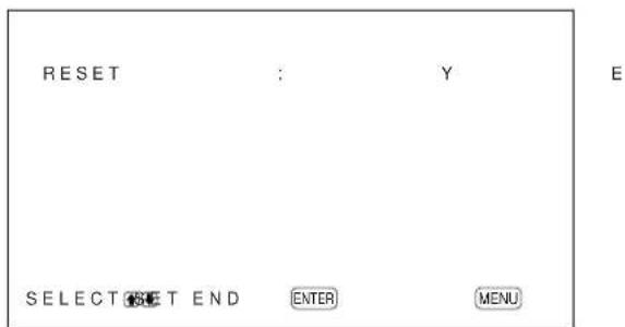
3 Press ENTER.
The PIC CONTROL menu items are restored.
To cancel the reset function
Press MENU before pressing ENTER.
Resizing and Positioning the Picture
You can shift the position of the picture so that it fits the screen, or adjust the vertical and horizontal size of the picture separately.
Resizing the Picture
1 Press MENU.
The main menu appears on the display panel.

2 Press / to move the cursor (▶) to "PIC SIZE" and press ENTER.
The PIC SIZE menu appears on the display panel.
3 Press / to move the cursor (▶) to "H SIZE" and press ENTER.
The following menu appears on the display panel.
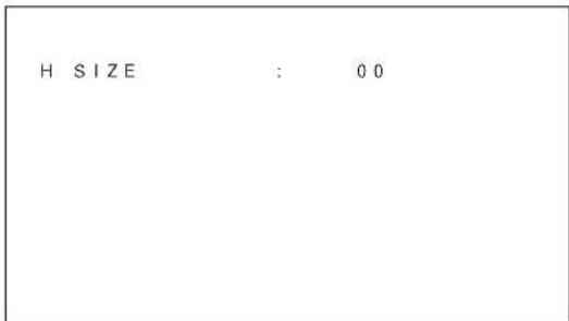
4 Press / to resize the picture.
to increase the horizontal size
: to reduce the horizontal size
The horizontal picture size is indicated on the display panel in the range from MIN (-50) to MAX (+50) . The factory preset value is 00.
Note
The lower limit of the setting may be above the MIN depending on the input signal type.
5 Press ENTER.
The menu returns to the PIC SIZE menu.
6 Press / to move the cursor (▶) to "V SIZE" and press ENTER.
The following menu appears on the display panel.
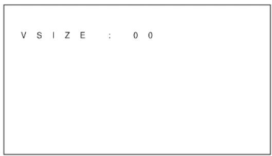
7 Press / to resize the picture.
to increase the vertical size
: to reduce the vertical size
The vertical picture size is indicated on the display panel in the range from MIN (-50) to MAX (+50) . The factory preset value is 00.
8 Press ENTER.
The menu returns to the PIC SIZE menu.
Adjusting the Picture Position
1 In the PIC SIZE menu, press / to move the cursor () to "H SHIFT" and press ENTER.
The following menu appears on the display panel.
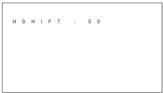
2 Press / to shift the picture.
to shift the picture to the right
: to shift the picture to the left
The horizontal picture position is indicated on the display panel in the range from MIN (-50) to MAX (+50) . The factory preset value is 00.
3 Press ENTER.
The menu returns to the PIC SIZE menu.
4 Press / to move the cursor (▶) to "V SHIFT" and press ENTER.
The following menu appears on the display panel.
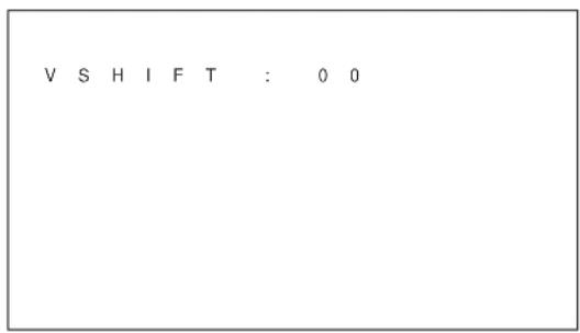
5 Press / to shift the picture.
to shift the picture upward
: to shift the picture downward
The vertical picture position is indicated on the display panel in the range from MIN (-50) to MAX (+50) . The factory preset value is 00.
6 Press ENTER.
The menu returns to the PIC SIZE menu.
Restoring the Original Picture Size and Position
1 In the PIC SIZE menu, press / to move the cursor () to "RESET" and press ENTER.
The following menu appears on the display panel.
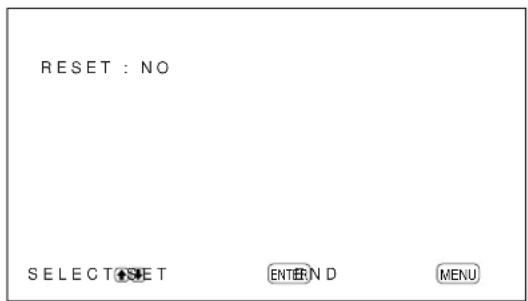
2 Press / .
"NO" changes to "YES".
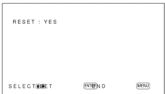
3 Press ENTER.
The original picture size and position are restored.
To cancel the reset function
Press MENU before pressing ENTER.
Changing the Aspect Ratio
This device can display images in various aspect ratios, such as the normal 4:3 TV program ratio, a widescreen image, etc. That means you can choose a suitable aspect ratio to display images.
1 In the PIC SIZE menu, press / to move the cursor () to "ASPECT" and press ENTER.
The following menu appears on the display panel.
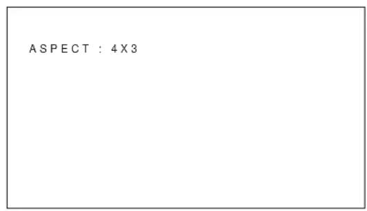
2 Select an aspect ratio item with / and press ENTER.
4 × 3 : to display a standard 4:3 image
16 × 9 : to display a 16:9 widenscreen image
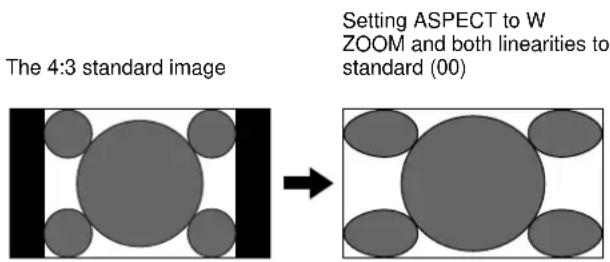
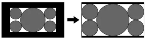
W ZOOM: to enlarge a 4:3 image to a 16:9 screen naturally as illustrated below
LB (letterbox) ZOOM: to enlarge images in various aspect ratios to fit proportionally to the left and right sides of the screen as illustrated below
Widescreen image such as CinemaScope, VistaVision, etc.
Setting ASPECT to LB ZOOM
Notes
- If you select W ZOOM or LB ZOOM, it is recommended that you set the H SIZE, H SHIFT, V SIZE and V SHIFT to the standard (00). If you change them too much, a W ZOOM or LB ZOOM display may be distorted. Before you select W ZOOM or LB ZOOM, set ZOOM to × 1 . If ZOOM is set to × 2 , × 3 or × 4 , W ZOOM or LB ZOOM cannot be selected.
- B lack bands may display at the top and bottom of the screen depending on the input signal type.
Adjusting the Linearities
When you select W ZOOM for ASPECT, you can change the linearities by adjusting the H LINEARITY and V LINEARITY settings.
1 In the ASPECT menu, press / to move the cursor (▶) to "W ZOOM" and press ENTER. The following menu appears on the display panel.
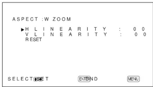
2 Press / to move the cursor () to "H LINEARITY" or "V LINEARITY" and press ENTER.
H LINEARITY: to change the linearity in the horizontal direction
V LINEARITY: to change the linearity in the vertical direction
The following menu appears on the display panel. (The illustration below is for selecting H LINEARITY.)
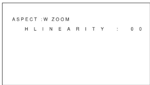
3 Adjust the linearity with / .
To restore wide zoom mode items to their original settings
In the ASPECT menu, select W ZOOM and press ENTER. Press / to move the cursor () to "RESET" and press ENTER. Then select YES with / and press ENTER.
Adjusting the Pixels
If there is too much noise on the edges of the characters or the vertical lines, you can adjust the dot phase and the total number of horizontal pixels.
1 Press MENU.
The main menu appears on the display panel.
2 Press / to move the cursor (▶) to "PIC SIZE" and press ENTER.
The PIC SIZE menu appears on the display panel.

3 Press / to move the cursor (▶) to "PIXEL ADJUST" and press ENTER.
The following menu appears on the display panel.
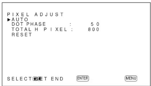
4 You can adjust the dot phase and the total number of horizontal pixels automatically or manually.
Adjusting automatically
(1) Select AUTO with / and press ENTER. The following menu appears on the display panel.
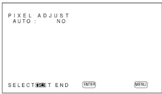
(2) Select YES with / and press ENTER. The dot phase and the total number of horizontal pixels are adjusted automatically.
Adjusting manually
(1) Select DOT PHASE or TOTAL H Pixel with / and press ENTER. The following menu appears on the display panel. (The illustration below is for selecting DOT PHASE.)
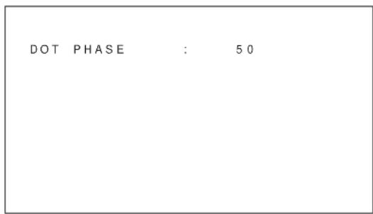
(2) Adjust the dot phase or the total number of horizontal pixels with / and press ENTER.
To restore Pixel ADJUST menu items to their original settings
In the PILXEL ADJUST menu, press / to move the cursor () to "RESET" and press ENTER. Then select YES with / and press ENTER.
Notes
- D ot phase adjustment is effective for computer signals (except for UXGA and above).
- When noise can't be eliminated using Adjusting automatically, make fine Adjusting manually.
- A cross-hatch pattern is convenient for use as the input signal when adjusting the dot phase.
Using the Memory Function
You can save the current picture setting for each input signal using the MEMORY function. The saved settings can be restored whenever necessary. The items in the PIC CONTROL and PIC SIZE menus can be memorized. You can save the picture settings of up to twenty input signals. You can name the settings of the items (up to 10 characters in length).
Storing the Current Setting
1 Press MENU.
The main menu appears on the display panel.
2 Press / to move the cursor (▶) to "MEMORY" and press ENTER.
The MEMORY menu appears on the display panel.

3 Press / to move the cursor (▶) to "SAVE" and press ENTER.
The following menu appears on the display panel.
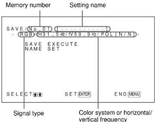
If there is no data in the selected memory number, the “-- EMPTY --” message appears on the display panel in cyan. The signal type and the color system or horizontal/vertical frequency are displayed in cyan (showing that the signal type of the selected memory number is the same as that of the current setting) or in yellow (showing that the signal type of the selected memory number is not the same as that of the current setting).
4 Select a memory number (01 to 20) with / and press ENTER.
The cursor () appears on the display panel.
5 Press / to move the cursor (▶) to "SAVE EXECUTE" and press ENTER.
The current data is stored under the selected memory number. The "SAVE COMPLETED" message appears for about five seconds.
When you name the setting, follow the steps below.
6 Press ENTER, then press / to move the cursor () to "NAME SET" and press ENTER again. The following menu appears on the display panel.
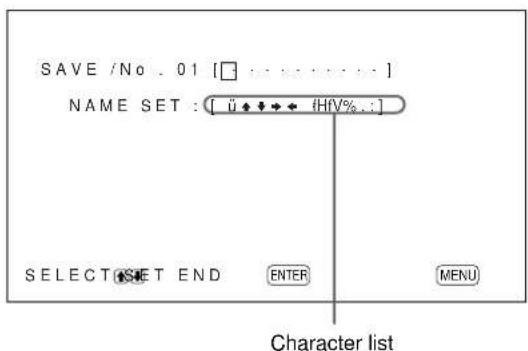
7 Select the character to be changed with / and press ENTER.
The background of a character in the character list changes to cyan.
8 Select a character in the character list with / and press ENTER.
The selected character is input.
9 Repeat steps 7 and 8 until you finish inputting the name, then press MENU.
The menu returns to the SAVE menu.
Note
If the storing of the setting fails, the "SAVE ERROR" message appears on the display panel. Try to store the setting again.
Calling Up a Stored Setting
1 In the MEMORY menu, press / to move the cursor () to "LOAD" and press ENTER.
The first page of the stored settings appears on the display panel.
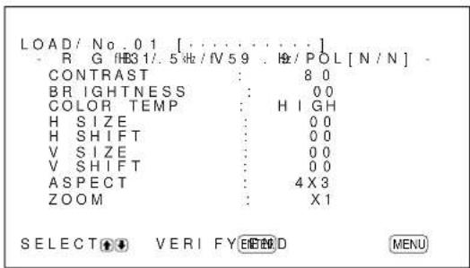
2 Select a memory number (01 to 20) with / and press ENTER.
The second page of the stored settings appears on the display panel.
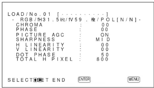
The signal type and the color system or horizontal/ vertical frequency are displayed in cyan (showing that the signal type of the selected memory number is the same as that of the current setting and you can call up the stored setting) or in red (showing that the signal type of the selected memory number is not the same as that of the current setting and you cannot call up the stored setting).
3 Press ENTER.
The "LOAD COMPLETED" message appears for about five seconds and the picture is adjusted to the selected setting.
Note
If the loading fails, the "LOAD ERROR" message appears on the display panel. Try to load the setting again.
Selecting the On-screen Language
You can select the on-screen language from among English, German, French, Italian, Spanish or Japanese.
1 Press MENU.
The main menu appears on the display panel.
2 Press / to move the cursor (▶) to "CONFIG" and press ENTER.
The CONFIG (1/2) menu appears on the display panel.
3 Press / to move the cursor () to
"LANGUAGE" on the CONFIG (2/2) menu and press ENTER.
The following menu appears on the display panel.
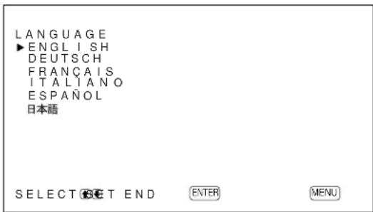
4 Press / to move the cursor () to the desired language and press ENTER.
The on-screen language is switched to the one you selected.
ENGLISH: English
DEUTsCH:German
FRANÇAIS: French
ITALIANO: Italian
ESPANOL: Spanish
日本語:Japanese
5 Press MENU.
The menu returns to the CONFIG (2/2) menu.
Reducing Afterimage/ Ghosting (Screen Saver Function)
If an image like a computer screen or a still picture, the brightness of which does not change, is displayed for a long time, this image may be burnt into the panel or may leave a ghosting image behind. To avoid this, or to attempt to fix it, a screen saver function has been provided with this unit. The screen saver function has two screen savers. One screen saver reverses the image (PIC INVERSION) while the other automatically changes the position of the image displayed (PIC ORBITING).
Reversing the Image
1 Press MENU.
The main menu appears on the display panel.
2 Press / to move the cursor (▶) to "CONFIG" and press ENTER.
The CONFIG (1/2) menu appears on the display panel.
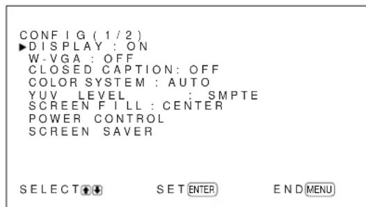
3 Press / to move the cursor (▶) to "SCREEN Saver" and press ENTER.
The following menu appears on the display panel.
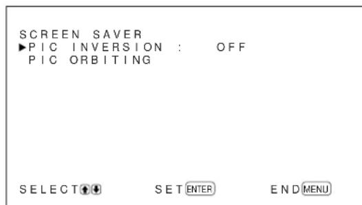
4 Press / to move the cursor (▶) to "PIC INVERSION" and press ENTER.
The following menu appears on the display panel.
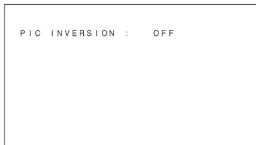
5 Select the PIC INVERSION mode with /
OFF: to set the PIC INVERSION to OFF
ON: to set the PIC INVERSION to ON
AUTO: Carry out the PIC INVERSION process once a day.
When you select AUTO, the following menu appears.

(1) Press ENTER.
The cursor () appears on the display panel.
(2) Press / to move the cursor () to "START TIME" and press ENTER.
The following menu appears and the background of the hour is displayed in cyan.
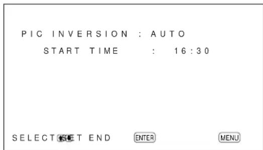
(3) Set the hour when the image is to be reversed with / and press ENTER.
The setting for the hour is entered and the background of the minute is displayed in cyan.
(4) Set the minute with / and press MENU.
The setting for the minute is entered and the menu returns to the PIC INVERSION menu.
(5) Similarly, set the time when the PIC
INVERSION function is to be cancelled. The display image will be reversed at the START TIME and will return to the original display image at the END TIME. This cycle is carried out automatically once a day.
To set the change to the standby mode at the END TIME
1 After selecting AUTO for PIC INVERSION mode, select POWER OFF and press ENTER.
The following menu appears on the display panel.
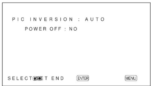
2 Select YES with / and press MENU.
The display changes to standby mode at the designated END TIME.
Notes
The power off function, power saving function and on/off timer function in the POWER CONTROL menu cannot be used simultaneously. When one of those functions is set to ON (YES), "--" appears next to the others and their functions are not available.
- If you set START TIME and END TIME to the same time, the setting of START TIME takes priority over that of END TIME. The display image does not return to the original image at the END TIME.
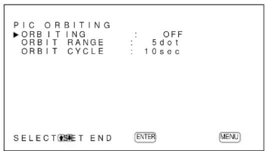
Changing the Image Position Automatically
1 In the SCREEN Saver menu, press / to move the cursor (▶) to "PIC ORBITING" and press ENTER.
The following menu appears on the display panel.
2 Press / to move the cursor (▶) to
"ORBITING" and press ENTER.
The following menu appears on the display panel.
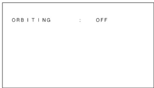
3 Select the ORBITING mode with /
OFF: Cancel the PIC ORBITING function.
ON: Set the PIC ORBITING function.
4 Press MENU.
The menu returns to the PIC ORBITING menu.
5 Select ORBIT RANGE (moving distance) or ORBIT CYCLE (time) with / and press ENTER.
The following values can be selected:
ORBIT RANGE: 5dot, 10dot, 15dot, 20dot
ORBIT CYCLE: 10sec, 30sec, 1min, 5min
The following menu appears on the display panel. (The illustration below is for selecting ORBIT RANGE.)
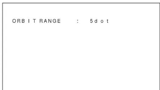
6 Adjust the ORBIT RANGE or ORBIT CYCLE with / and press MENU.
When both PIC INVERSION and PIC ORBITING are set to ON
If the PIC ORBITING function is actuated while the picture is reversed, the reversed picture is displayed changing position.
Controlling Power On/Off Automatically (Power Control Function)
This display has two power controlling functions. You can set one to turn off the power automatically after a certain period if there is no input signal from the INPUT1 or INPUT2 connectors (POWER SAVING function). You can set the time when the power automatically turns on/off (ON/OFF TIMER function). The PFM-42B2/42B2E has ON TIMER and OFF TIMER functions for which you can individually set the power on/off times.
Energy Saving Function (PFM-42B2/ 42B2E only)
1 Press MENU.
The main menu appears on the display panel.

2 Press / to move the cursor (▶) to "CONFIG" and press ENTER.
The "CONFIG" (1/2) menu appears on the display panel.
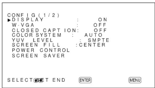
3 Press / to move the cursor (▶) to "POWER CONTROL" and press ENTER.
The following menu appears on the display panel.
4 Press / to move the cursor () to "ENERGY SAVING" and press ENTER.
The following menu appears on the display panel.

5 Press / to select the ENERGY SAVING Mode ON/OFF.
OFF: No energy saving
ON: energy saving
By enabling the ENERGY SAVING (ON), the screen brightness is reduced and you can view the display unit while saving energy.
Power Saving Function
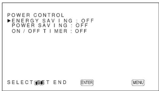
1 In the CONFIG (1/2) menu, press / to move the cursor () to "POWER CONTROL" and press ENTER.
The following menu appears on the display panel.
PFM-42B1/42B1E: "ENERGY SAVING" is not displayed.
2 Press / to move the cursor (▶) to "POWER SAVING" and press ENTER.
The following menu appears on the display panel.
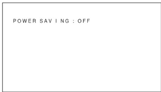
3 Press / to select the length of time until the change to power saving mode.
OFF: The power saving function does not work.
5min: Changes to the power saving mode after five minutes if there is no input signal.
10min: Changes to the power saving mode after 10 minutes if there is no input signal.
The ON indicator flashes when the unit is in the power saving mode.
To cancel the power saving function
- Input the sync signal again.
- Press the switch on the (standby) switch / indicator section or the POWER ON switch on the Remote Commander.
Signal specification for using the power saving function
The sync signal should be connected to the 13th pin of the RGB/YUV (D-sub 15-pin) connector in the INPUT1 or INPUT2 connectors.
On/Off Timer Function
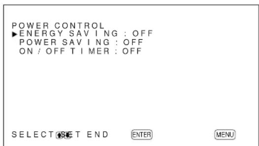
1 In the CONFIG (1/2) menu, Press / to move the cursor () to "POWER CONTROL" and press ENTER.
The following menu appears on the display panel.

PFM-42B1/42B1E: "ENERGY SAVING" is not displayed.
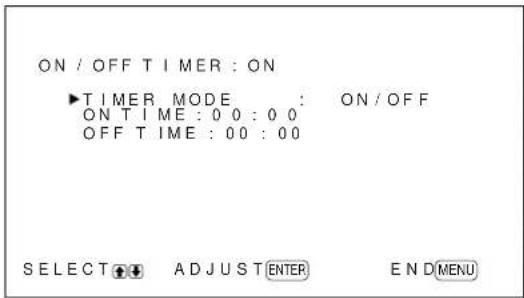
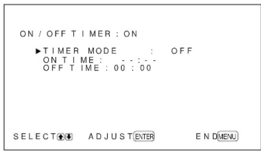
2 Press / to move the cursor (▶) to "ON/OFF TIMER" and press ENTER. The following menu appears on the display panel.
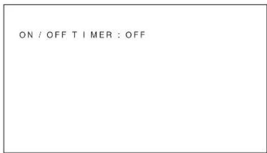
3 Select ON with / and press ENTER. The following menu appears on the display panel.
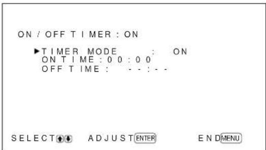
Note
The screen being displayed may differ depending on the timer mode previously set. The steps described here assume that the last timer mode has been set to ON. The factory default is ON/OFF.
4 Press ENTER again on this screen to select the timer mode. The following menu appears on the display panel.
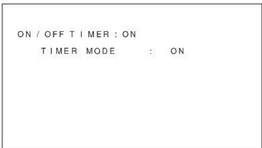
5 Press / to move the cursor (▶) to "ON/OFF" and press ENTER. The following menu appears on the display panel.
6 Press / to move the cursor () to "POWER ON TIME" and press ENTER. The following menu appears on the display panel. The area behind the hour is displayed in light blue.
7 Press / to set the hour and press ENTER. The time is entered and the area behind the minutes is displayed in blue.
8 Press / to set the minute and press ENTER.
9 Press / to move the cursor (▶) to "POWER OFF TIME" and press Enter. Do the same thing for the power on hour and minute. When the power-off timer expires, the system power is turned off, the standby mode is activated, and the ON indicator flashes.
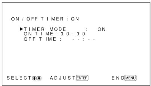
On Timer Function (PFM-42B2/ 42B2E only)
1 When the Step 4 screen in the ON/OFF TIMER function is displayed, select ON with / and press ENTER.
The following menu appears on the display panel.
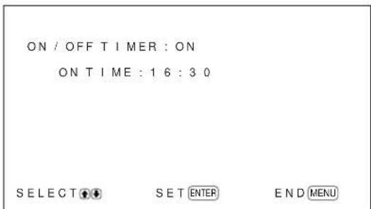
2 Press / to select "ON TIME" and press ENTER.
The following menu appears on the display panel. The area behind the hour is displayed in light blue.
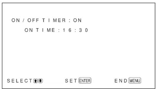
3 Press / to set the hour and press ENTER. The time is entered and the area behind the minute is displayed in blue.
4 Press / to set the minute and press ENTER. If the system turns off the power and goes into the standby mode, the ON indicator flashes.
Off Timer Function (PFM-42B2/ 42B2E only)
1 When the Step 4 screen in the ON/OFF TIMER function is displayed, select OFF with / and press ENTER.
The following menu appears on the display panel.
2 Press / to select "OFF TIME" and press ENTER.
The following menu appears on the display panel. The area behind the hour is displayed in light blue.
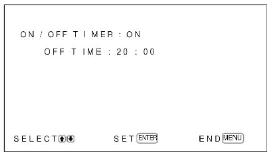
3 Press / to set the hour and press ENTER. The time is entered and the area behind the minute is displayed in blue.
4 Press / to set the minute and press ENTER. The display unit changes to the wait mode when the power-off timer turns off.
Notes
The power saving function does not work when the signal is input from the VIDEO connectors.
- If the sync signal is not connected to the 13th pin of the RGB/YUV (D-sub 15-pin) connector in the INPUT1 or INPUT2 connectors, the display unit does not turn on even if the sync signal is input. Be sure to set POWER SAVING to OFF when only an RGB signal is connected.
The power saving function, on/off timer function and power off function in the PIC INVERSION mode cannot be used simultaneously. When one of those functions is set to ON (YES), "---" appears next to the others and their functions are not available.
- If you set ON TIME and OFF TIME to the same time, the setting of ON TIME takes priority over that of OFF TIME. The display unit does not turn off at the OFF TIME.
Setting the SERIAL REMOTE (PFM-42B2/42B2E only)
You can set the serial remote controls.
Setting the baud rate
This parameter is used to synchronize the baud rate to the controlled device.
The factory default is 9600bps.
1 Press MENU.
The main menu appears on the display panel.
2 Press / to move the cursor (▶) to "CONFIG" and press ENTER.
The CONFIG (1/2) menu appears on the display panel.
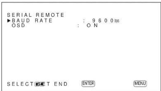
3 Press / move the cursor (▶) to "SERIAL REMOTE" on the CONFIG (2/2) menu and press ENTER.
The following menu appears on the display panel.

4 Press / to move the cursor () to "BAUD RATE" and press ENTER.
The following menu appears on the display panel.
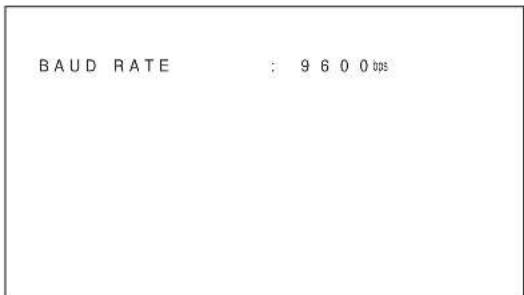
5 Select the baud rate (9600bps, 19200bps or 38400bps) with / and press ENTER.
6 Press MENU.
The menu returns to the CONFIG (2/2) menu.
OSD Function
If the system is controlled by the Serial Remote mode, the controlled functions appear on the screen.
You can hide the serial remote data as follows:
1 In the CONFIG (2/2) menu, Press / to move the cursor () to "SERIAL REMOTE" and press ENTER.
The following menu appears on the display panel.
2 Press / to move the cursor (▶) to "OSD" and press ENTER.
The following menu appears on the display panel.

3 Press / to set OSD to OFF and press ENTER. The serial remote data is not shown.
To display the serial remote data Set OSD to ON in step 3 above. The factory default is ON.
Setting the NETWORK ADAPTOR (PFM-42B2/42B2E only)
Sets the network adaptor.
Setting the power supply to the Network Adaptor
The power is supplied to the Network Adaptor even if the system is in the standby mode. You can disable the power supply in the standby mode as follows:
1 Press MENU. The main menu appears on the display panel.
2 Press / to move the cursor (▶) to "CONFIG" and press ENTER. The CONFIG (1/2) menu appears on the display panel.
3 Press / to move the cursor (▶) to "NETWORK ADAPTOR" on the CONFIG (2/2) menu and press ENTER. The following menu appears on the display panel.
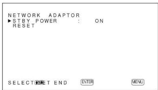
4 Press / to move the cursor (▶) to "STBY POWER" and press ENTER. The following menu appears on the display panel.

5 Press / to set STBY POWER to OFF and press ENTER. If the system is in the standby mode, the power is not supplied to the Network Adaptor.
To supply the power Set STBY POWER to ON in step 5 above. The factory default is ON.
If the screen freezes when you use the Network Adaptor
Reset the screen as follows:
1 In the CONFIG (2/2) menu, Press / to move the cursor () to "NETWORK ADAPTOR" and press ENTER.
The following menu appears on the display panel.
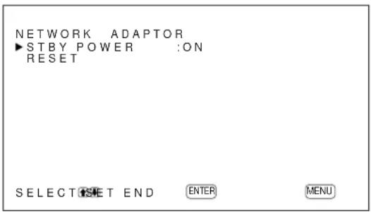
2 Press / to move the cursor (▶) to "RESET" and press ENTER.
The following menu appears on the display panel.
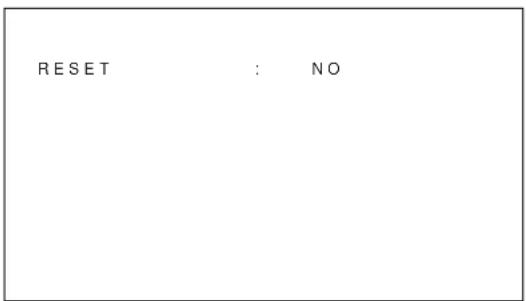
3 Press / to set RESET to YES and press ENTER.
The Network Adaptor is restarted.
Self-diagnosis Function
The unit has a self-diagnosis function.
This function shows the display's condition based on the pattern shown by the flashing of the STANDBY indicator. The flashing pattern informs you of the display's current condition.
If the STANDBY indicator flashes, check the number of flashes and contact your authorized Sony dealer.
1 Check the flashing pattern of the STANDBY indicator.
The indicator flashes (with an image showing on the display) or flashes at intervals of three seconds (with no image showing on the display).
Count the number of flashes if the indicator flashes at intervals of three seconds. For example, the indicator flashes twice, followed by a three second pause, two more flashes and this pattern repeats. In this case, the count for the number of flashes is two.
2 Unplug the unit.
Inform your authorized Sony dealer of the number of flashes.
Operating a Specific Display With the Remote Commander
Using the supplied Remote Commander, you can operate a specific display without affecting other displays that are installed at the same time.
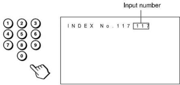
1 Press ID MODE ON on the Remote Commander. Monitor index numbers appear in white characters on all the displays. (Every display is allocated an individual preset index number from 1 to 255.) See "To change the index number" in the right-hand column on the next page to change the index number.

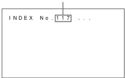
Index number
2 Input the index number of the display you want to operate using the 0-9 buttons on the Remote Commander.
The input number appears right next to the index number of each display.
3 Press ID MODE SET.
The characters on the selected display change to cyan while the others change to red.

You can operate only the display specified. (All operations are available in ID mode except power on/off.)
4 After the necessary adjustment, press ID MODE OFF.
The display returns to the normal mode.

To change the index number
You can change the index number if necessary. When you change the number, use the buttons on the control button section of the display unit.
1 Press MENU.
The main menu appears on the display panel.

2 Press / to move the cursor (▶) to "REMOTE" and press ENTER.
The REMOTE menu appears on the display panel.
3 Press / to move the cursor (▶) to "INDEX No." and press ENTER.
The following menu appears on the display panel.
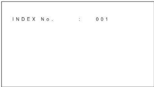
4 Select the index number with / and press ENTER.
The menu returns to the REMOTE menu.
Using Other Remote Commander Models
The following operations can be carried out using other Remote Commander models.
- Power on/off
-Input selection - Menu operations
- Picture adjustments: contrast, phase and chroma
- On-screen display on/off
The operations available and the buttons to be used for each operation are limited depending on each Remote Commander. See the table below.
| Remote Commander model | RM-854 RM-921 RM-PJ1001 | ||
| REMOTE MODE setting TV TV PJ | |||
| Input selection INPUT | T1 RGB R | RGB1 A | |
| INPUT2 — RGB2 B | |||
| VIDEO LINE1 LINE VIDEO | |||
| Menu operation | MENU | MENU | MENU or ← |
| ENTER | ENTER ENTER | ENTER or → | |
| ▲ | + | SELECT+↑ ↑ | |
| ▼ | - | SELECT-↓ ↓ | |
| Picture adjustment | Contrast | CONTRAST+/- | — |
| Chroma | CHROMAL-— | COLOR R+/- | |
| Phase | PHASE+/- | — HUE+/- | |
| On-screen information | DISPLAY | DISPLAY STATUS ON | |
Specifications
Video processing
Preset signal See page 26 (GB).
Sampling rate 13.5MHz to 140MHz
Panel system AC-type Plasma Display Panel
Display resolution 1024 dots (horizontal) × 1024 lines (vertical)
Pixel pitch 0.90 (horizontal) × 0.51 (vertical) mm (%16× %32 inches)
Picture size 921 (horizontal) × 522 (vertical) mm (36%)× 20% inches
Panel size 42-inch (diagonal 1058mm )
Inputs and Outputs
INPUT1/INPUT2
RGB/YUV D-sub 15-pin (female) (See "Pin assignment" on page 48 (GB).)
AUDIO Stereo minijack 500 mVrms, high impedance
VIDEO (NTSC, PAL, SECAM, NTSC4.43, PAL60, PAL-M)1)
COMPOSITE IN BNC (× 1) Composite video, 1Vp - p± 2 dB sync negative,75-ohm (automatic termination)
Y/C IN Mini DIN 4-pin (× 1) Y (luminance): 1Vp - p± 2 dB sync negative,75-ohm terminated C (chrominance):Burst 0.286Vp - p± 2 dB NTSC), 75-ohm terminated Burst 0.3Vp - p± 2 dB PAL), 75-ohm terminated
AUDIO IN Stereo minijack 500 mVrms, high impedance
COMPOSITE OUT
BNC (× 1) Loop-through
AUDIO OUT Stereo minijack 500 mVrms, high impedance
REMOTE (RS-232C) D-sub 9-pin (× 1)
Safety regulations
UL1950, CSA No. 950 (c-UL), FCC Class B, IC Class B, EN60 950 (NEMKO), CE, C-Tick
Component Input Adaptor (with Control S) BKM-B12 (Not supplied)
INPUT3
RGB/YUV Phono jack (female) (× 3)
CONTROL S (IN/OUT)
Stereo minijack (× 2) 5Vp - p
Video Input & Control S Adaptor BKM-B13 (Not supplied)
VIDEO (NTSC, PAL, SECAM, NTSC4.43, PAL60, PAL-M)
COMPOSITE IN BNC (× 1) Composite video, 1Vp - p± 2 dB sync negative, 75-ohm (automatic termination)
Y/C IN Mini DIN 4-pin (× 1) Y (luminance): 1Vp - p± 2 dB sync negative,75-ohm terminated C (chrominance):Burst 0.286Vp - p± 2 dB NTSC), 75-ohm terminated Burst 0.3Vp - p± 2 dB PAL), 75-ohm terminated
COMPOSITE OUT
BNC (× 1) loop-through
CONTROL S (IN/OUT)
Stereo minijack (× 2) 5Vp - p
General
Power requirements
100 V to 240 V AC, 50/60 Hz, PFM-42B1/42B1E:
4.5 A to 1.8 A
PFM-42B2/42B2E:
4.2 A to 1.5 A
Power consumption
PFM-42B1/42B1E: 400 W
PFM-42B2/42B2E:360W
Operating conditions
Temperature: 0^ to 35^ (32^ to 95^)
Humidity: 20% to 90% (no condensation)
Atmospheric pressure: 800 to 1060hPa
Storing/transporting conditions
Temperature: -10^ to +40^ (14°F to 104°F)
Humidity: 20% to 90% (no condensation)
Atmospheric pressure: 800 to 1060hPa
Dimensions 1033× 631× 83mm
(40% × 24% × 3% inches)
(w/h/d, excluding projections)
Mass PFM-42B1/42B1E:
29.4 kg (64 lb 13 oz)
PFM-42B2/42B2E:
28.4 kg (62 lb 10 oz)
Supplied accessories
AC power cord (1)
AC plug holder (2)
Cable holder A (2)
Cable holder B (4)
Ferrite Cores (2) (PFM-42B2/ 42B2E only)
Stoppers (2) (PFM-42B2/42B2E only)
Remote Commander RM-42B (1)
Size AA (R6) batteries (2)
Operating instructions (1)
Optional accessories
Display stand SU-42B
Video input adaptor BKM-B10 (for the PFM-42B1E/42B2E only)
Component Input Adaptor (with Control S) BKM-B12
Video Input & Control S Adaptor BKM-B13
Network Adaptor BKM-B30NW
Design and specifications are subject to change without notice.
Pin assignment
RGB/YUV connector (D-sub 15-pin)
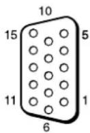
| Pin No. Signal | |
| 1 Red video or R-Y or PR | |
| 2 Green video (Composite Sync On Green) or Y | |
| 3 Blue video or B-Y or PB | |
| 4 Ground | |
| 5 Ground | |
| 6 Red ground | |
| 7 Green ground | |
| 8 Blue ground | |
| 9 Not used | |
| 10 Ground | |
| 11 Ground | |
| 12 SDA | |
| 13 H sync or composite sync | |
| 14 V sync | |
| 15 SCL |
AVENTISSEMENT
Raccordements. 14 (FR)
Specifications 47 (FR)
Précautions
Sécurité
16 Touches ID MODE (ON/SET/OFF)
UL1950, CSA No. 950 (c-UL),
FCC Class B, IC Class B,
EN60 950 (NEMKO), CE,
C-Tick
± 2 dB (NTSC), 75 ohms
(termination)
Salve 0,3 Vcc ± 2 dB (PAL),
75 ohms (terminaison)
COMPOSITE OUT
PFM-42B1/42B1E: 400 W
PFM-42B2/42B2E:360W
± 2 dB (NTSC), 75-Ohm
EN60 950 (NEMKO), CE, C-
Tick
± 2 dB (NTSC), 75-Ohm
PFM-42B1/42B1E: 400 W
PFM-42B2/42B2E:360W
16 Tasti ID MODE (ON/SET/OFF)
21 LIVELLO YUV (solo PFM-42B2E)
27 SERIAL REMOTE (solo PFM-42B2E)
UL1950, CSA N. 950 (c-UL), FCC
Class B, IC Class B, EN60 950
(NEMKO), CE, C-Tick
Nuclei in ferrite (2) (solo PFM42B2E)
Fermi (2) (solo PFM-42B2E)
Telecomando RM-42B (1)
Pile R6 (formato AA) (2)
Printed on recycled paper
「二一業務用製品相談窓口の案内」に線口
Sony Corporation Printed in Japan