AcousticDesign ADS32T - Speaker QSC - Free user manual and instructions
Find the device manual for free AcousticDesign ADS32T QSC in PDF.

User questions about AcousticDesign ADS32T QSC
0 question about this device. Answer the ones you know or ask your own.
Ask a new question about this device
Download the instructions for your Speaker in PDF format for free! Find your manual AcousticDesign ADS32T - QSC and take your electronic device back in hand. On this page are published all the documents necessary for the use of your device. AcousticDesign ADS32T by QSC.
USER MANUAL AcousticDesign ADS32T QSC
AcousticDesign™ Series
QSC™
User Guide
AD-S6T - 6" two-way, foreground/background loudspeaker with 70/100V transformer
AD-S8T - 8" two-way, foreground/background loudspeaker with 70/100V transformer
AD-S10T - 10" two-way, foreground/background loudspeaker with 70/100V transformer
AD-S12 - 12" two-way, foreground/background loudspeaker
AD-S112sw - 12" direct-radiating subwoofer
natural_image
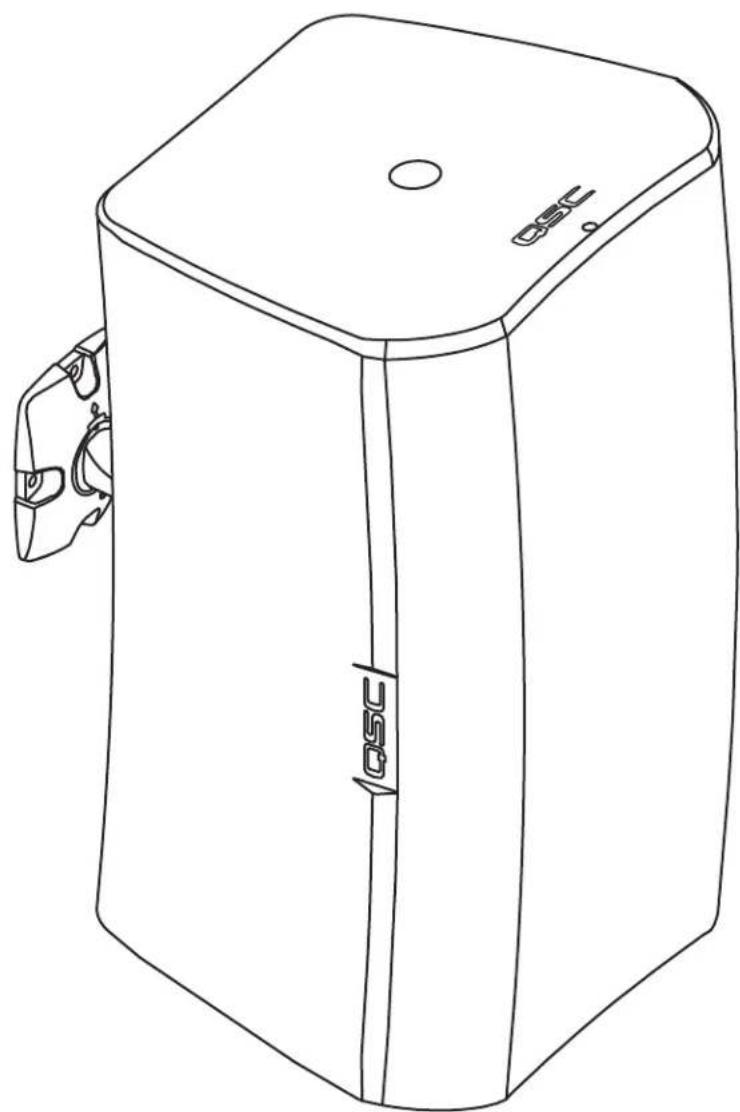
Line drawing of a rectangular electronic device with a lid and label 'OSC' (no text or symbols on the device itself)TD-000329-00-C
*TD-000329-00*

EXPLANATION OF SYMBOLS
The term "WARNING!" indicates instructions regarding personal safety. If the instructions are not followed the result may be bodily injury or death.
The term "CAUTION!" indicates instructions regarding possible damage to physical equipment. If these instructions are not followed, it may result in damage to the equipment that may not be covered under the warranty.
The term "IMPORTANT!" indicates instructions or information that are vital to the successful completion of the procedure.
The term "NOTE" is used to indicate additional useful information.

NOTE: The intent of the lightning flash with arrowhead symbol in a triangle is to alert the user to the presence of un-insulated "dangerous" voltage within the product's enclosure that may be of sufficient magnitude to constitute a risk of electric shock to humans.

NOTE: The intent of the exclamation point within an equilateral triangle is to alert the user to the presence of important safety, and operating and maintenance instructions in this manual.

IMPORTANT SAFETY INSTRUCTIONS


WARNING!: TO PREVENT FIRE OR ELECTRIC SHOCK, DO NOT EXPOSE THIS EQUIPMENT TO RAIN OR MOISTURE.

WARNING!: While it is possible for one person to lift a loudspeaker, it is important to use proper lifting techniques. Suggested reading: OSHA Technical Manual on Back Disorders and Injuries (http://www.osha.gov/dts/osta/otm/otm_vii/otm_vii_1.html#app_vii:1_2).
- Keep these instructions.
- Heed all warnings.
- Follow all instructions.
- Clean only with a dry cloth.
- Do not install near any heat sources such as radiators, heat registers, stoves, or other apparatus (including amplifiers) that produce heat.
- Only use attachments/accessories specified by the manufacturer.
- Refer all servicing to qualified service personnel.
- Adhere to all applicable, local codes.
- Consult a licensed, professional engineer when any doubt or questions arise regarding a physical equipment installation.
Introduction
AcousticDesign series is a line of premium surface-mount loudspeakers intended for permanent installation applications. Housed in rugged ABS molded enclosures, each loudspeaker (except the AD-S12 and AD-S112sw) features a 70/100V transformer for use with distributed-audio lines. The unique X-Mount™ Bracket and Euro-style connector, supplied with each AcousticDesign loudspeaker, are designed for maximum flexibility and a quick install. Featuring a knurled ball-mount and discrete angle deployment marks, installers can set loudspeaker deployment angles quickly and securely. The Euro-style connector allows pre-wiring of the system and when combined with the quick "snap-on" deployment of the loudspeaker to the mount, installation is completed in a fraction of the time required versus competitive models.
Unpacking
Package Contents
- Quick-Start Guide
- AcousticDesign Loudspeaker
-
Euro-style Connector, 4-pin
-
Terminal Weather Protection Cover
- Phillips Screws (4) M4 (Terminal Weather Protection Cover)
- X-Mount™ Bracket (Yoke Mount for AD-S112sw)
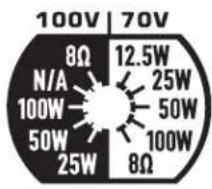
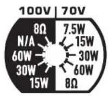
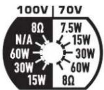
Set the Transformer Tap Switch
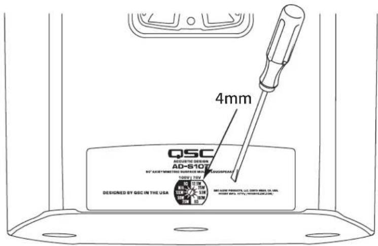
Refer to – Figure 1
- Insert a 4mm fl at-tip screwdriver into Transformer Tap hole and engage the slot.
- At fully clockwise the transformer is in 8Ω-bypass.
AD-S10T
| 100 Volt 70 Volt | |
| 8 Ω8 Ω | |
| N/A 100W | |
| 100W 50W | |
| 50W 25W | |
| 25W 12.5W | |
text_image
100V | 70V 8Ω 12.5W N/A 25W 100W 50W 50W 100W 25W 8Ω- Figure 2 -
- Table 1 -
text_image
4mm QSC ACQUATIC DESIGN AD-S107 R' ARBITMETHI SURFACE RED CLOWSPEAT 100V / 70V DESIGNED BY QSC IN THE USA R' ARBIT MOUNTS, U.S. DART MEAL CO., INC. ARBIT MOUNTS, R'ARBITMETHI CO., INC.- Figure 1 -
AD-S6T, AD-S8T
| 100 Volt 70 Volt | |
| 8 Ω8 Ω | |
| N/A 60W | |
| 60W 30W | |
| 30W 15W | |
| 15W 7.5W | |
text_image
100V | 70V 8Ω 7.5W N/A 15W 60W 30W 30W 60W 15W 8Ω- Figure 3 -
- Table 2 -
EN
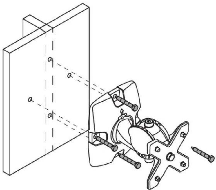
Mount the Loudspeakers
Install the X-Mount™ Bracket
Refer to – Figure 4

WARNING!: Install the system in accordance with local building codes and regulations. Use a licensed contractor or professional engineer. QSC Audio Products is not responsible for damages resulting from the negligent installation of any bracket or loudspeaker.
- Mount to a surface capable of supporting the weight of the loudspeaker.
natural_image
Technical line drawing of a mechanical assembly with fasteners and a bracket, no text or symbols present- Figure 4 -
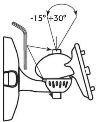
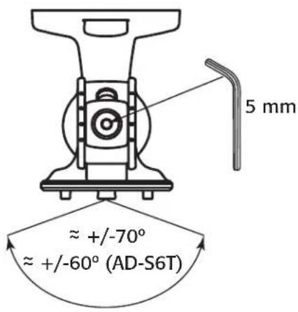
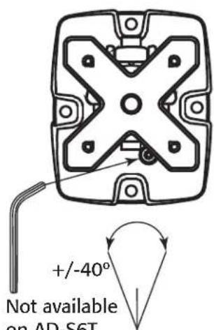
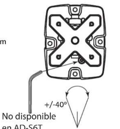
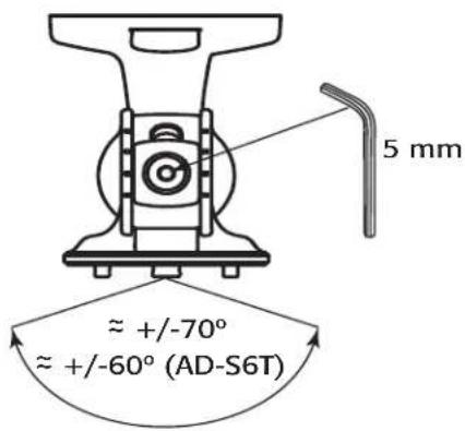
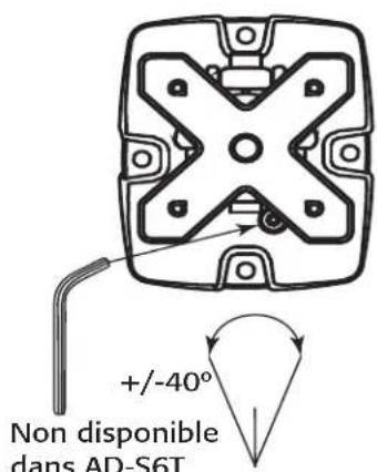
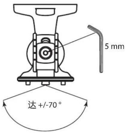
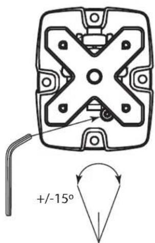
Adjust the Angle of the X-Mount™ Bracket
Refer to – Figure 5

NOTE: This step may be done now or after mounting the loudspeaker.
- Use a 5mm hex wrench to loosen the adjustment locking screws.
- Orient the bracket as necessary.
text_image
-15° +30°SIDE
text_image
5 mm ≈ +/-70° ≈ +/-60° (AD-S6T)TOP
text_image
+/ -40° Not available on AD-S6TFRONT
- Figure 5 -
- Tighten the adjustment locking screws.
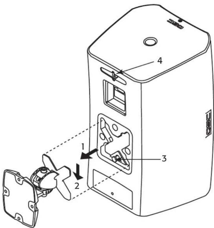
Mount the Loudspeaker on the Bracket
Refer to – Figure 6.

NOTE: The loudspeaker can be placed on the mount in ANY direction (Up, Down, Left, Right).
- Align the "X" slot with the X-Mount™ bracket and push the loudspeaker onto the bracket. (1)
- When seated, pull the loudspeaker down to lock the loudspeaker onto the bracket. (2)
- (Optional) Remove and retain the security tab (3); pull straight out. To remove the loudspeaker, re-install the security tab, press in and then remove the loudspeaker.
Connect a Safety Tether (Not supplied)

WARNING!: DO NOT connect the tether to the mounting bracket or the screws holding the mounting bracket.
- It is recommended that you connect a safety tether from the safety ring (4) on the back of the loudspeaker to a spot on the wall that is structurally sufficient to hold the weight of the loudspeaker in the event the loudspeaker should fall.
text_image
Technical diagram of a device with numbered components and labeled parts, showing internal assembly and component alignment.- Figure 6 -
EN
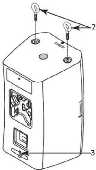
Suspend the Loudspeaker
Refer to – Figure 7

WARNING!: Suspend the loudspeaker in accordance with local building codes and regulations. Use a licensed contractor or professional engineer. QSC Audio Products is not responsible for damages resulting from the negligent installation of suspension cabling, or loudspeaker.
The AcousticDesign loudspeakers (models AD-S8T, AD-S10T and AD-S12) may be suspended using the pull-back point and M10 eyebolts you install at the bottom of the enclosures.

NOTE: Suspending the enclosure woofer side up positions the HF closer to the listener and helps improve bass response when coupled against the ceiling and wall planes.
- Remove 2 M10 plugs (not shown) from the bottom of the loudspeaker enclosure.
- Install two M10-1.5 eyebolts (2) (accessory M10 Kit-C) in the M10 installation points on the bottom of the loudspeaker enclosure.
- Attach an appropriate cable to the tether Safety Ring (3) for the pull-back point.
text_image
Technical diagram of a device with labeled components and light indicators- Figure 7 -
Yoke-mount the Loudspeaker
In addition to the mounting methods listed above, you can mount the loudspeaker using the optional Yoke mounting kit. Refer to instructions provided in the Yoke kit. See the "Specifications" on page 12 for information.
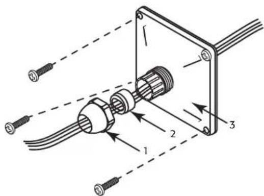
Install the Weather Cover (Optional)
Refer to – Figure 8
- Slide the nut (1), compression gasket (2), and weather cover / gasket (3) over the wiring for the loudspeaker.
- Terminate the wiring to the Euro-style connector, refer to "Wire the Loudspeaker" on page 6
- Install the Euro-style connector.
- Slide the weather cover/gasket (3) up next to the connection box, use a small amount of wire, inside the cover, to provide strain relief.
- Attach the weather cover to the enclosure with four screws (supplied).
- Slide the compression gasket (2) into the weather cover receptacle.
- Slide the nut over the weather cover receptacle and tighten.
text_image
Technical diagram of a cable connector assembly with labeled parts and wiring connections- Figure 8 -
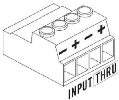
Wire the Loudspeaker
Use up to 12 gage wiring as appropriate. Refer to — Figure 9.
- If you are using the optional weather cover, make sure the wiring is inserted through all three parts of the weather cover in the proper order.
- Install the negative and positive wires in the "Input" +/- as shown. Tighten the wire-clamp screws.
- Install the daisy-chaining wires into the "Thru" +/- as shown. These wires go to the next loudspeaker in the daisy-chain.
text_image
INPUT THRU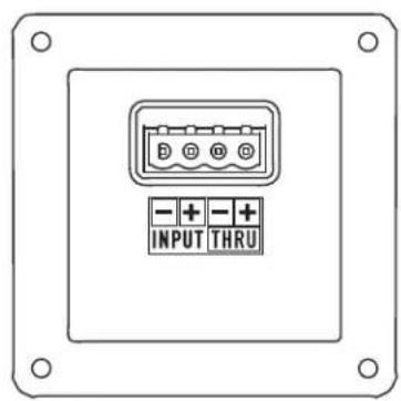
text_image
- + INPUT - + THRU- Figure 9 -
Remove the Loudspeaker
- Make sure all the wiring is disconnected, and the safety tether is removed.
- If the security tab, located at the base of the loudspeaker mount, has NOT been removed, push the tab in and slide the loudspeaker in the opposite direction of how it was installed.
- If the security tab has been removed, re-insert it, or use a small rod (<4 mm / 0.16") to push in and release the mount lock.
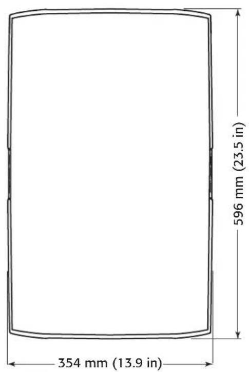
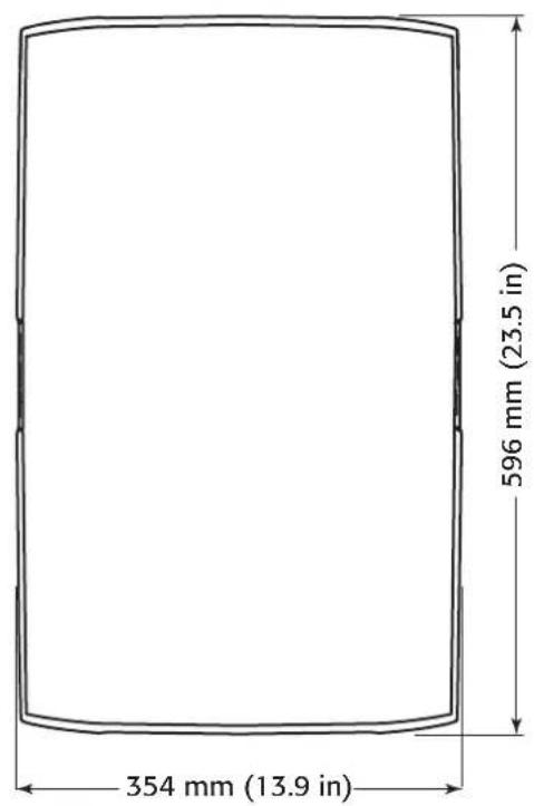
AD-S12 Dimensions
text_image
354 mm (13.9 in) 596 mm (23.5 in)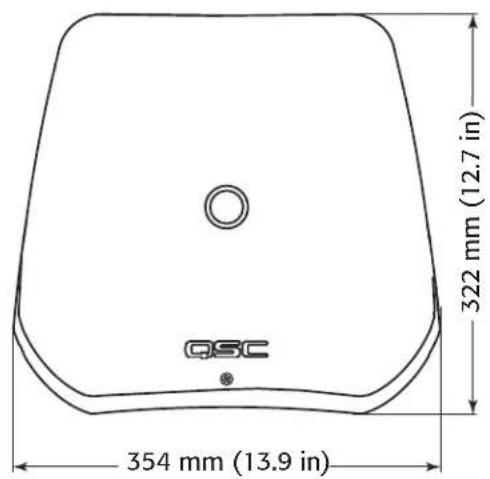
text_image
QSC 354 mm (13.9 in) 322 mm (12.7 in)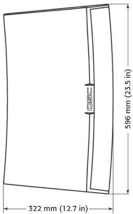
text_image
322 mm (12.7 in) 596 mm (23.5 in)- Figure 10 -
EN
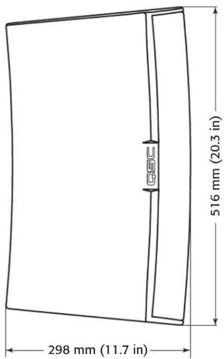
AD-S10T Dimensions

text_image
318 mm (12.5 in) 516 mm (20.3 in)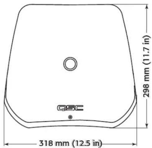
text_image
QSC 318 mm (12.5 in) 298 mm (11.7 in)EN
text_image
298 mm (11.7 in) 516 mm (20.3 in)- Figure 11 -
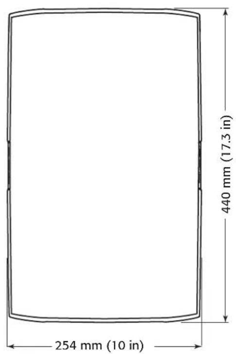
AD-S8T Dimensions
text_image
254 mm (10 in) 440 mm (17.3 in)
text_image
254 mm (10 in) 251 mm (9.9 in) QSC
text_image
251 mm (9.9 in) 440 mm (17.3 in)- Figure 12 -
EN
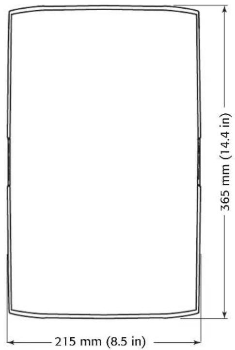
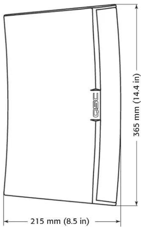
AD-S6T Dimensions
text_image
215 mm (8.5 in) 365 mm (14.4 in)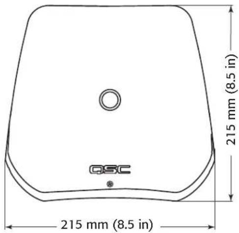
text_image
215 mm (8.5 in) QSC 215 mm (8.5 in)EN
text_image
215 mm (8.5 in) 365 mm (14.4 in)- Figure 13 -
AD-S112sw Dimensions

text_image
354 mm (13.9 in) 596 mm (23.5 in)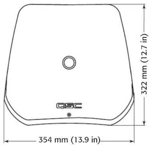
text_image
QSC 322 mm (12.7 in) 354 mm (13.9 in)
text_image
322 mm (12.7 in) 596 mm (23.5 in)- Figure 14 -
EN
Specifications
AD-S6T AD-S8T AD-S10T
| Configuration 6" 2-way with transformer 8" 2-way with transformer 10" 2-way with transformer | |||
| Effective Frequency Range (-10 dB)1 | 60 - 20 kHz 55 - 20 kHz 50 - 19 kHz | ||
| Rated Voltage / Power2 | 35 Vrms / 150 W 40 Vrms / 200 W 45 Vrms / 250 W | ||
| Broad-band Sensitivity3 | 89 dB SPL 90 dB SPL 92 dB SPL | ||
| Coverage Angle (-6 dB)4 | 105° 105° 90° | ||
| Directivity Factor (Q) 5 | 7 | 10 | |
| Directivity Index | 7 dB 9 dB | 10 dB | |
| Maximum SPL Continuous (1 m)5 | 110 dB | 113 dB | 116 dB |
| Maximum SPL Peak (1 m)5 | 116 dB | 119 dB | 122 dB |
| Nominal Impedance | 8Ω | 8Ω | 8Ω |
| Recommended Amplifier Power | 300 W | 400 W | 500 W |
| Transformer Tap 70 V | 60, 30, 15, 7.5 W and 8Ω bypass | 60, 30, 15, 7.5 W and 8Ω bypass | 100, 50, 25, 12.5 W and 8Ω Bypass |
| Transformer Tap 100 V | 60, 30, 15 W and 8Ω bypass | 60, 30, 15 W and 8Ω bypass | 100, 50, 25 W and 8Ω Bypass |
| High-frequency Transducer | 1" silk dome tweeter / 1" voice-coil horn loaded | 1" Exit / 1.4" Voice-coil Compression Driver | 1" Exit / 1.4" Voice-coil Compression Driver |
| Low-frequency Transducer | 6" weather resistant paper cone woofer, 38 mm / 1.5" voice-coil | 8" Weather Resistant Paper Cone Woofer, 50 mm / 2" Voice-coil | 10" Weather Resistant Paper Cone Woofer, 64 mm / 2.5" Voice-coil |
| Input Connector | Euro-style Connector with Parallel Output | ||
| Enclosure Details | |||
| Material | ABS Polymer | ||
| Finish | Black RAL 9011 or White RAL 9010 Paint | ||
| Grille | Powder-coated Aluminum | ||
| X-Mount Material | Powder-coated Aluminum | ||
| Ingress Protection | Meets IP-54 for dust and splash resistance. | ||
| Operating Environment | Designed for indoor and outdoor use | ||
| Operating Temperature Range | -20 to 50 °C / -4 to 122 °F | ||
| Testing: Qualifi ed for outdoor use using the following tests: | Salt fog: MIL-STD-810G Method 509.5 for 100 hrs.Humidity: MIL-STD-810G Method 507.5, Natural cycle B2, cyclic high RH for 7 daysHigh and low temperature: tested to QSC internal standards between -20° and 50°C | ||
| Weight (Net) | 6.2 kg / 13.6 lbs | 11 kg / 24 lbs | 14 kg / 31 lbs |
| Dimensions (HWD) | 365 mm x 215 mm x 215 mm14.4" x 8.5" x 8.5" | 440 mm x 254 mm x 251 mm17.3" x 10.0" x 9.8" | 516 mm x 318 mm x 298 mm20.3" x 12.5" x 11.7" |
| Included Accessories | X-MountTM system, Euro-style connector, input panel cover | X-MountTM system, Euro-style connector | X-MountTM system, Euro-style connector |
| Optional Accessories | N/A | Yoke Mount Bracket Kit - YMS8T-WHT / YMS8T-BLKM10 Kit-C | Yoke Mount Bracket Kit - YMS10T-WHT / YMS10T-BLKM10 Kit-C |
1 Free-fi eld, -10 dB from on-axis sensitivity
2 IEC60268-1 noise signal for 2 Hrs
3 On-Axis, free-fi eld sensitivity, 2.83V, 1 m
4 Coverage angle measured with 3 - 10 kHz bandwidth
5 Calculated from rated noise voltage and sensitivity
Specifications
AD-S12 AD-S112sw
| Configuration 12" 2-way 12" direct-radiating subwoofer | ||
| Effective Frequency Range (-10 dB)1 | 52 - 20 kHz 30 - 135 Hz | |
| Rated Voltage / Power2 | 50 Vrms / 300 W 50 Vrms / 300 W | |
| Broad-band Sensitivity3 95 dB SPL 90 dB SPL | ||
| Coverage Angle (-6 dB)4 | 75° M10 Kit-C | |
| Directivity Factor (Q) 12 N/A | ||
| Directivity Index 11 dB | N/A | |
| Maximum SPL Continuous (1 m)5 | 120 dB | 115 dB |
| Maximum SPL Peak (1 m)5 | 126 dB | 121 dB |
| Nominal Impedance | 8Ω 8Ω | |
| Recommended Amplifi er Power | 600 W | 600 W |
| Transformer Tap 70 V | N/A | N/A |
| Transformer Tap 100 V | N/A | N/A |
| High-Frequency Transducer | 1" Exit / 1.4" Voice-coil Compression Driver | N/A |
| Low-frequency Transducer | 12" Weather Resistant Paper Cone Woofer, 64 mm / 2.5" Voice-coil | 12" weather resistant paper cone woofer, 64 mm / 2.5" voice-coil |
| Input Connector | Euro-style Connector with Parallel Output | |
| Enclosure Details | ||
| Material | ABS Polymer | |
| Finish | Black RAL 9011 or White RAL 9010 Paint | Black RAL 9011 Paint |
| Grille | Powder-coated Aluminum | |
| Yoke Material | Powder coated galvanized steel | |
| Ingress Protection Meets IP-54 for dust and splash resistance. | ||
| Operating Environment | Designed for indoor and outdoor use | |
| Operating Temperature Range | -20 to 50 °C / -4 to 122 °F | |
| Testing: Qualifi ed for outdoor use using the following tests: | Salt fog: MIL-STD-810G Method 509.5 for 100 hrs.Humidity: MIL-STD-810G Method 507.5, Natural cycle B2, cyclic high RH for 7 daysHigh and low temperature: tested to QSC internal standards between -20° and 50°C | |
| Weight (Net) | 16 kg / 35.0 lbs | 13.2 kg / 29 lbs |
| Dimensions (HWD) | 596 mm x 354 mm x 323 mm23.5" x 13.9" x 12.7" | 596 mm x 354 mm x 322 mm23.5" x 13.9" x 12.7" |
| Included Accessories | X-MountTM system, Euro-style connector | 596 mm x 354 mm x 323 mm23.4" x 13.9" x 12.7" |
| Optional Accessories | Yoke Mount Bracket Kit - YMS12-WHT / YMS12-BLK M10 Kit-C | M10 Kit-C |
1 Free-fi eld, -10 dB from on-axis sensitivity
2 IEC60268-1 noise signal for 2 Hrs
3 On-Axis, free-fi eld sensitivity, 2.83V, 1 m
4 Coverage angle measured with 3 - 10 kHz bandwidth
5 Calculated from rated noise voltage and sensitivity
QSC™
Mailing Address:
QSC Audio Products, LLC
1675 MacArthur Boulevard
Costa Mesa, CA 92626-1468 USA
Telephone Numbers:
Main Number: (714) 754-6175
Sales & Marketing: (714) 957-7100 or toll free (USA only) (800) 854-4079
Customer Service: (714) 957-7150 or toll free (USA only) (800) 772-2834
Facsimile Numbers:
Sales & Marketing FAX: (714) 754-6174
Customer Service FAX: (714) 754-6173
World Wide Web:
www.qsc.com
E-mail:
info@qsc.com
service@qsc.com
Serie AscousticDesign™
Guía del usuario
natural_image
Line drawing of a rectangular electronic device with a lid and front panel, no text or symbols presenttext_image
100V | 70V 8Ω 7.5W N/A 15W 60W 30W 30W 60W 15W 8Ω- Figure 3 -
Monte los altavoces
natural_image
Technical line drawing of a mechanical assembly with screws and a star-shaped component, no text or symbols present- Figure 4 -
text_image
5 mm ≈ +/-70° ≈ +/-60° (AD-S6T) NCARA SUPERIOR
text_image
m +/-40° No disponible en AD-S6TCARA DELANTERA
- Figure 5 -
text_image
Technical diagram of a device with numbered components and labeled parts, showing internal structure and assembly steps.- Figure 6 -
Cuelgue el altavoz
Consulte Figure 7.

text_image
Technical diagram of a device with labeled components and light indicators- Figure 7 -
text_image
Technical diagram of a cable connector assembly with labeled parts and wiring connections- Figure 8 -
text_image
INPUT THRU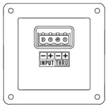
text_image
- + INPUT THRU- Figure 9 -
Retire el altavoz
QSC Audio Products, LLC
1675 MacArthur Boulevard
text_image
100V | 70V 8Ω 7.5W N/A 15W 60W 30W 30W 60W 15W 8Ω- Figure 3 -
natural_image
Technical line drawing of a mechanical assembly with fasteners and a bracket, no text or symbols present- Figure 4 -
text_image
-15° +30°CÔTÉ
text_image
5 mm ≈ +/-70° ≈ +/-60° (AD-S6T)DESSUS
text_image
Technical diagram of a device with numbered components and labeled parts, showing internal assembly and component alignment.- Figure 6 -
text_image
Technical diagram of a device with labeled components and directional arrows indicating flow or movement.- Figure 7 -
text_image
Technical diagram of a cable connector assembly with labeled parts and wiring connections- Figure 8 -
text_image
INPUT THRU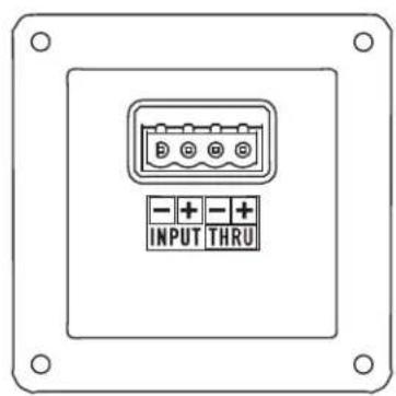
text_image
B + - + INPUT THRU- Figure 9 -
QSC Audio Products, LLC
1675 MacArthur Boulevard
natural_image
Line drawing of a rectangular electronic device with a lid and label 'DSU' on its side (no additional text or symbols)text_image
4mm QSC ACQUATIC DESIGN AD-S107 BY:ACQUITYMEETING SURFACE WITH COOLISPEAK 100V / 70V DESIGNED BY QSC IN THE USA BY:ACQUITY MEETING SURFACE WITH COOLISPEAK BY:ACQUITY MEETING SURFACE WITH COOLISPEAK BY:ACQUITY MEETING SURFACE WITH COOLISPEAK- Figure 1 -
AD-S6T, AD-S8T
| 100 V 70 V | |
| 8 Ω8 Ω | |
| -- 60 W | |
| 60 W 30 W | |
| 30 W 15 W | |
| 15 W 7,5 W | |
text_image
100V | 70V 8Ω 7.5W N/A 15W 60W 30W 30W 60W 15W 8Ω- Figure 3 -
- Table 2 -
natural_image
Technical line drawing of a mechanical assembly with screws and a bracket, showing alignment and disassembly (no text or symbols)- Figure 4 -
text_image
Nicht in AD-S6T +/-40°text_image
Technical diagram of a device with numbered components and labeled parts, showing internal structure and assembly steps.text_image
Technical diagram of a device with labeled parts and directional arrows indicating components- Figure 7 -
text_image
Technical diagram of a cable connector assembly with numbered parts and wire connections- Figure 8 -
text_image
INPUT THRU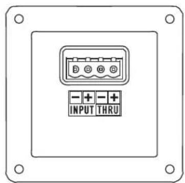
text_image
- + INPUT - + THRU- Figure 9 -
QSC Audio Products, LLC
1675 MacArthur Boulevard
Costa Mesa, CA 92626-1468 USA
Telefonnummern:
text_image
100V | 70V 8Ω 7.5W N/A 15W 60W 30W 30W 60W 15W 8Ω— 图 3 —
—表2—
安装扬声器
安装 X-Mount™ 支架
请参阅图 4。

natural_image
Technical line drawing of a mechanical assembly with screws and a bracket, showing alignment and disassembly (no text or symbols)— 图 4 —
调整 X-Mount™ 支架的角度
请参阅图 5。

text_image
-15°/+30°侧面
text_image
5 mm 达 +/-70°顶部
text_image
+/-15°正面
一图5一
3.拧紧固定螺丝。
在支架上安装扬声器
请参阅图6。

text_image
Technical diagram of a device with labeled parts and directional arrows indicating assembly or component alignment.— 图 6 —
悬挂扬声器
请参阅图7。

text_image
Technical diagram of a device with labeled parts and light indicators, showing internal components and connections.一图7一
使用轭安装扬声器
text_image
Technical diagram showing cable installation with labeled components and wiring connections—图8—
为扬声器接线
text_image
INPUT THRU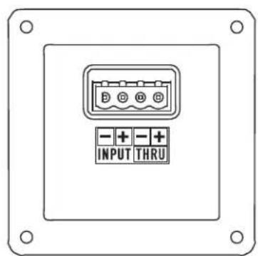
text_image
D D G - + - + INPUT THRU— 图 9 —
拆卸扬声器
text_image
215 mm (8.5 in) 215 mm (8.5 in)CH

text_image
215 mm (8.5 in) 365 mm (14.4 in)一图13一
AD-S112sw 尺寸
text_image
354 mm (13.9 in) 596 mm (23.5 in)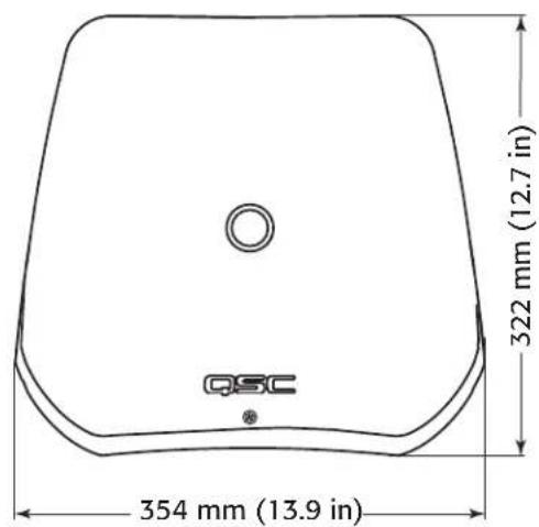
text_image
354 mm (13.9 in) 322 mm (12.7 in) QSC
text_image
322 mm (12.7 in) 596 mm (23.5 in)— 图 14 —
CH
规格
AD-S6T AD-S8T AD-S10T
QSC Audio Products, LLC
1675 MacArthur Boulevard
Costa Mesa, CA 92626-1468 USA
电话:
总机:(714) 754-6175