
SC422 - Speaker QSC - Free user manual and instructions
Find the device manual for free SC422 QSC in PDF.
User questions about SC422 QSC
0 question about this device. Answer the ones you know or ask your own.
Ask a new question about this device
Download the instructions for your Speaker in PDF format for free! Find your manual SC422 - QSC and take your electronic device back in hand. On this page are published all the documents necessary for the use of your device. SC422 by QSC.
USER MANUAL SC422 QSC
- Two-way, bi-amplified screen channel system
- HF-75 provides 90^ horizontal by +20^ to -30^ vertical coverage
• LF-4215 is constructed of MDF and features single woofer chambers - Low-distortion waveguide provides highly articulate dialogue
- Shallow depth (20") facilitates installation
natural_image
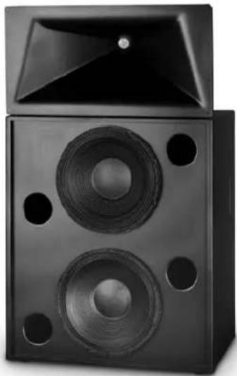
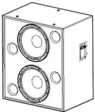
Black studio speaker chamber with two speakers and a top cover (no visible text or symbols)Developed specifically for the unique requirements of professional motion picture playback, the SC-422 extends QSC's commitment to the cinema market. As a member of the DCS Digital Cinema Speaker Series, the SC-422 is a two-way, bi-amplified screen channel loudspeaker system comprised of two main units—the HF-75 high-frequency system and the LF-4215 low-frequency system.
The HF-75 high-frequency system features a large format, 3" (75mm) titanium diaphragm compression driver mounted on a custom designed high-frequency cinema horn with an adjustable pan and tilt bracket. The HF-75 includes a driver protection and equalization network. DC blocking capacitors protect against DC or low-frequency signals that would likely destroy an unprotected driver. Power limiter circuitry protects the driver from overpowering and a response correction filter smoothes the frequency response of the horn/ driver combination. The driver and equalization network provides for more reliable operation, ensuring the show will go on.
The LF-4215 dual 15" (381mm) low-frequency enclosure is designed specifically to address the extended low-frequency response required for cinema applications. The LF-4215 covers the frequency range from 35 Hz to 1000 Hz, depending upon the high-frequency system requirements. Close Coupled Woofers (CCW), with their tight spacing between woofers, improves coupling and keeps coverage angles wide over a greater frequency range than more widely spaced designs.
The SC-422 is designed for ease of installation. The HF-75 components come pre-assembled to reduce field assembly time. Three bolts are all that are required to secure the HF-75 to the top of the LF-4215 enclosure.
| Specifications | SC-422 | |
| Nominal Coverage | 90° horizontal x +20 to -30° vertical | |
| Frequency Range | 38 Hz - 16 kHz (-6 dB) | |
| Crossover Frequency | 700 Hz, 24 dB per octave | |
| LF-4215 HF-75 | ||
| Impedance | 4Ω | 8Ω |
| Sensitivity 1 watt/1 meter, half space | 99.5 dB | 107.5 dB |
| Maximum Input Power ^1 | ||
| 8 hours of 6 db crest factor IEC 268 noise spectrum | 800 W RMS | 60 W RMS |
| 2 hours of 6 db crest factor pink noise, 50 Hz - 20 kHz, AES method | 1000 W RMS | 80 W RMS |
| Recommended Amplifier Power | 1600 W RMS maximum | 100 W RMS maximum |
| Recommended Processing | Subsonic filter below 30 Hz, >18 dB per octave | 4th order LR crossover at 1000 Hz |
| Connectors | Barrier strip screw terminals accept up to #10 AWG stranded wire, four terminals; two inputs and two parallel outputs | Barrier strip screw terminals accept up to #10 AWG stranded wire, four terminals; two inputs and two HF outputs |
| Transducers | Two 15" (381mm) high efficiency, extended bass woofer featuring 4" copper voice coils | 1.5" (38mm) exit, 3" titanium diaphragm compression driver |
| Enclosure | Quasi B4 alignment, ported enclosure with fully flared ports, symmetrical port design, tuned to 36 Hz, constructed of MDF and heavily braced. Features vandal resistant woofer mounting bolts | Tilt/Pan Bracket ±10° vertical tilt ±10° horizontal pan |
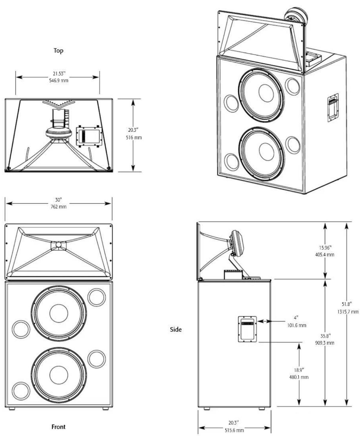
| Dimensions (HWD) | 36" x 30" x 20.3" (910 mm x 762 mm x 516 mm) | 16" x 30" x 20" (406 mm x 762 mm x 508 mm) |
| Weight - Net | 172 lbs (78 kg) | 40 lbs (18.4 kg) |
| System Weight | 212 lbs (96.4 kg) | |
| Baffle Cut-Out | 53" x 32" | |
1) Maximum input power tested in accordance with IEC 268-5 recommendations, 50 Hz - 20 kHz band limiting, 6 dB signal crest factor.
Specifications subject to change without notice.
Cinema Loudspeaker Systems User Manual
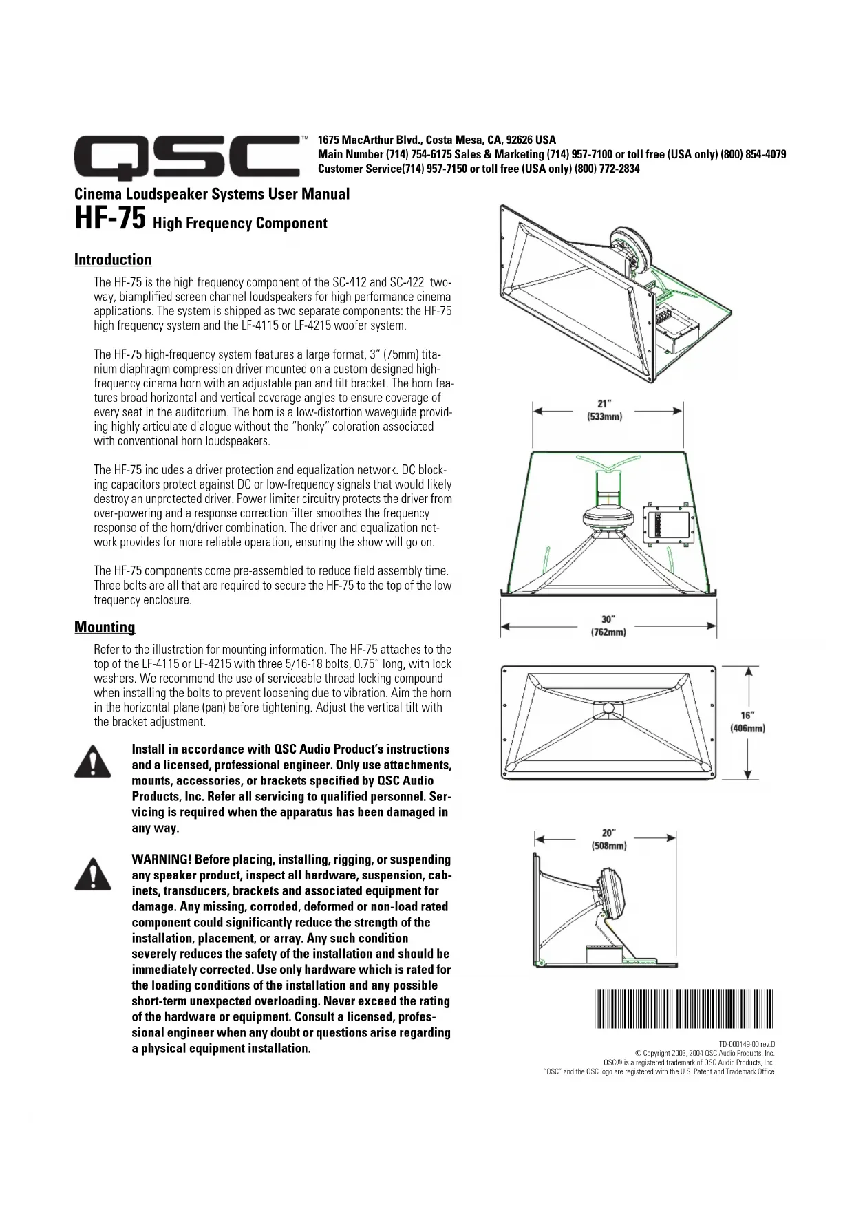
HF-75 High Frequency Component
Introduction
The HF-75 is the high frequency component of the SC-412 and SC-422 two-way, biamplified screen channel loudspeakers for high performance cinema applications. The system is shipped as two separate components: the HF-75 high frequency system and the LF-4115 or LF-4215 woofer system.
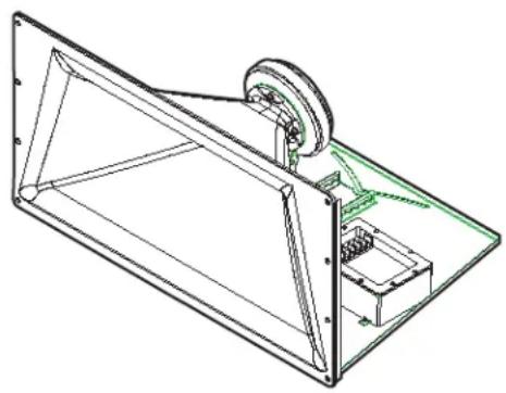
The HF-75 high-frequency system features a large format, 3" (75mm) titanium diaphragm compression driver mounted on a custom designed high-frequency cinema horn with an adjustable pan and tilt bracket. The horn features broad horizontal and vertical coverage angles to ensure coverage of every seat in the auditorium. The horn is a low-distortion waveguide providing highly articulate dialogue without the "honky" coloration associated with conventional horn loudspeakers.
The HF-75 includes a driver protection and equalization network. DC blocking capacitors protect against DC or low-frequency signals that would likely destroy an unprotected driver. Power limiter circuitry protects the driver from over-powering and a response correction filter smoothes the frequency response of the horn/driver combination. The driver and equalization network provides for more reliable operation, ensuring the show will go on.
The HF-75 components come pre-assembled to reduce field assembly time. Three bolts are all that are required to secure the HF-75 to the top of the low frequency enclosure.
Mounting
Refer to the illustration for mounting information. The HF-75 attaches to the top of the LF-4115 or LF-4215 with three 5/16-18 bolts, 0.75" long, with lock washers. We recommend the use of serviceable thread locking compound when installing the bolts to prevent loosening due to vibration. Aim the horn in the horizontal plane (pan) before tightening. Adjust the vertical tilt with the bracket adjustment.

Install in accordance with QSC Audio Product's instructions and a licensed, professional engineer. Only use attachments, mounts, accessories, or brackets specified by QSC Audio Products, Inc. Refer all servicing to qualified personnel. Servicing is required when the apparatus has been damaged in any way.

WARNING! Before placing, installing, rigging, or suspending any speaker product, inspect all hardware, suspension, cabinets, transducers, brackets and associated equipment for damage. Any missing, corroded, deformed or non-load rated component could significantly reduce the strength of the installation, placement, or array. Any such condition severely reduces the safety of the installation and should be immediately corrected. Use only hardware which is rated for the loading conditions of the installation and any possible short-term unexpected overloading. Never exceed the rating of the hardware or equipment. Consult a licensed, professional engineer when any doubt or questions arise regarding a physical equipment installation.
natural_image
Technical line drawing of a mechanical assembly with no visible text or symbols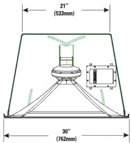
text_image
21" (533mm) 30" (762mm)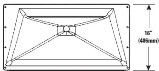
text_image
16" (406mm)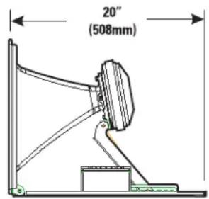
text_image
20" (508mm)
TD-000149-00 rev.D
© Copyright 2003, 2004 QSC Audio Products, Inc
QSC® is a registered trademark of QSC Audio Products, Inc.
"QSC" and the QSC logo are registered with the U.S. Patent and Trademark Office
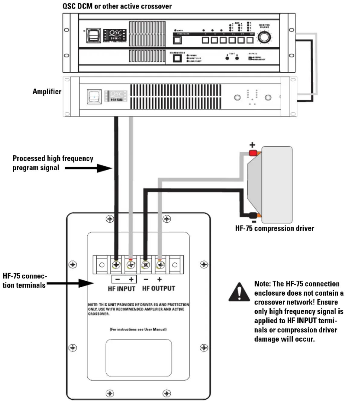
Connections
The HF-75 has barrier strip screw terminals that accept up to #10 AWG stranded loudspeaker wire.
HF INPUT Terminals
Connect the amplifier's output signal to the loudspeaker's HF INPUT terminals. Observe proper polarity; amplifier + signal to loudspeaker + HF INPUT, amplifier - signal to loudspeaker - HF INPUT. Use the largest wire size and shortest length for the application.

NOTE! Do not apply full range signal to the HF-75! There is no crossover in the HF-75, only a compensation/delay network. All required signal processing must be done upstream of the HF-75. Maintain proper loud-speaker connection polarity throughout the entire system for maximum performance.
HF OUTPUT Terminals
The HF OUTPUT terminals are factory-connected to the compression driver. These terminals should ONLY be connected to the HF-75's compression driver.
text_image
QSC DCM or other active crossover Amplifier Processed high frequency program signal HF-75 connection terminals HF-75 connection driver Note: The HF-75 connection enclosure does not contain a crossover network! Ensure only high frequency signal is applied to HF INPUT terminals or compression driver damage will occur. NOTE: THIS UNIT PROVIDES HF DRIVER EQ AND PROTECTION ONLY. USE WITH RECOMMENDED AMPLIFIER AND ACTIVE CROSSOVER. (For instructions see User Manual)
Note: The HF-75 connection enclosure does not contain a crossover network! Ensure only high frequency signal is applied to HF INPUT terminals or compression driver damage will occur.
HF-75 Specifications (subject to change without notice)
Frequency Range: 600 - 16kHz (-6 dB, full space)
Nominal Coverage:
90° horizontal X +15° to -35° vertical (50° total, adjustable mount provides for vertical plane adjustments. The horizontal plane can be adjusted by altering mounting position on the LF-4215 enclosure before tightening bolts.
DI: 9.0 dB (600 to 16,000 Hertz average)
Q: 8.0 (600 to 16,000 Hertz average)
Maximum Output: 133 dB SPL calculated peak, 1 meter, half space.
Impedance: 8 ohms nominal
8.0 ohms minimum at 3,000 Hertz
104 ohms maximum at 475 Hertz
Maximum Input Power:
60 watts rms (100 hours of 6 dB crest factor pink noise, 500 to 20,000 Hertz, IEC method)
80 watts rms (2 hours of 6 dB crest factor pink noise, 60 - 6,000 Hertz, AES method)
Sensitivity: 108 dB half space, 1 watt, 1 meter
Crossover Frequency: 700 Hertz or higher, 24 dB per octave
Connectors:
Barrier strip screw terminals accept up to #10 AWG stranded wire. Four terminals: (two HF INPUT and two post compensation HF OUTPUT). HF OUTPUT factory wired to compression driver.
Transducers: 1.5" (38mm) exit, 3.0" (76mm) titanium diaphragm compression driver.
Mounting Hardware:
Attaches to top of low frequency cabinet using three 5/16"-18 x 3/4" long bolts.
Size: 30" wide X 16" high X 20" deep (762mm X 406mm X 508mm)
Weight:
50 lbs. (shipping), 40 lbs. (net), 22.7/18.4 kilograms
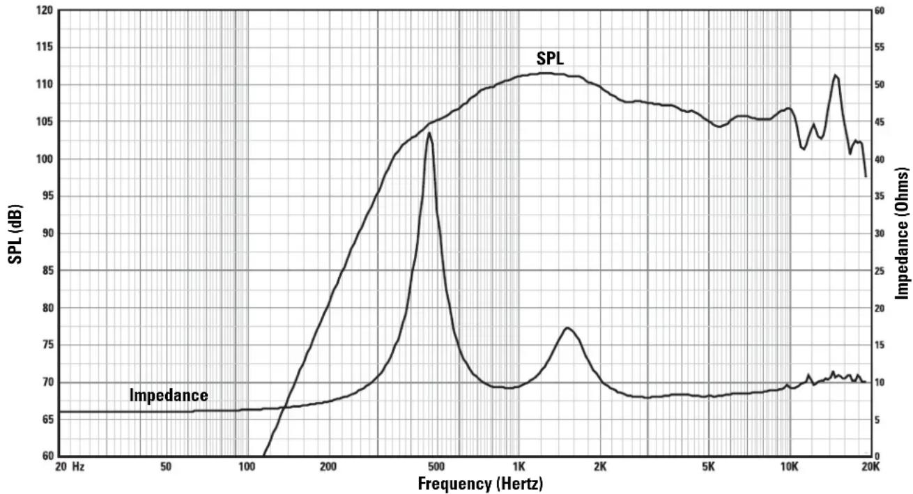
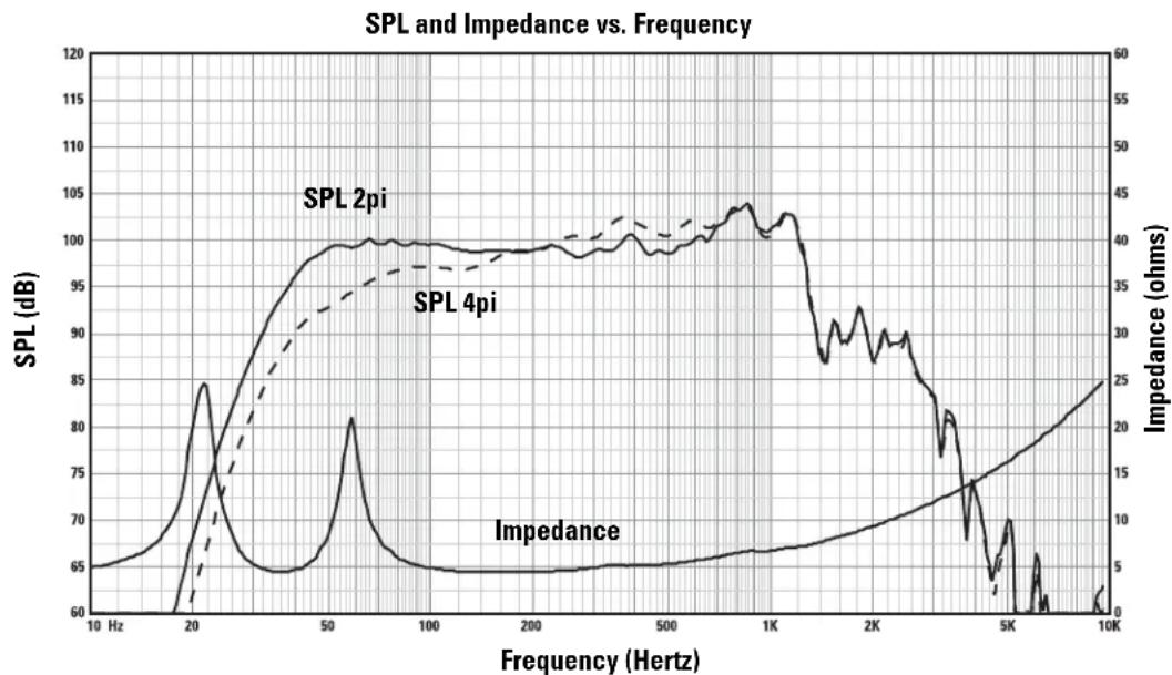
SPL and Impedance vs. Frequency
bar_line
| Frequency (Hz) | SPL (dB) | Impedance (Ohms) | | -------------- | -------- | ---------------- | | 20 | 65 | 5 | | 50 | 65 | 5 | | 100 | 65 | 5 | | 200 | 80 | 7 | | 500 | 103 | 15 | | 1K | 108 | 10 | | 2K | 107 | 9 | | 5K | 106 | 9 | | 10K | 107 | 10 | | 20K | 102 | 11 |Warranty (USA only; other countries, see your dealer or distributor)
Disclaimer
QSC Audio Products, Inc. is not liable for any damage to amplifiers, or any other equipment that is caused by negligence or improper installation and/or use of this loudspeaker product.
QSC Audio Products 3 Year Limited Warranty
QSC Audio Products, Inc. ("QSC") guarantees its products to be free from defective material and / or workmanship for a period of three (3) years from date of sale, and will replace defective parts and repair malfunctioning products under this warranty when the defect occurs under normal installation and use - provided the unit is returned to our factory or one of our authorized service stations via pre-paid transportation with a copy of proof of purchase (i.e., sales receipt). This warranty provides that the examination of the return product must indicate, in our judgment, a manufacturing defect. This warranty does not extend to any product which has been subjected to misuse, neglect, accident, improper installation, or where the date code has been removed or defaced. QSC shall not be liable for incidental and/or consequential damages. This warranty gives you specific legal rights. This limited warranty is freely transferable during the term of the warranty period.
Customer may have additional rights, which vary from state to state.
In the event that this product was manufactured for export and sale outside of the United States or its territories, then this limited warranty shall not apply. Removal of the serial number on this product, or purchase of this product from an unauthorized dealer, will void this limited warranty. Periodically, this warranty is updated. To obtain the most recent version of QSC's warranty statement, please visit www.qscaudio.com. Contact us at 800-854-4079 or visit our website at www.qscaudio.com.
Contacting QSC Audio Products
Mailing address: QSC Audio Products, Inc.
1675 MacArthur Boulevard
Costa Mesa, CA 92626-1468 USA
Telephone Numbers:
Main Number (714) 754-6175
Sales & Marketing (714) 957-7100 or toll free (USA only) (800) 854-4079
Customer Service(714) 957-7150 or toll free (USA only) (800) 772-2834
Facsimile Numbers:
Sales & Marketing Fax(714) 754-6174
Customer Service Fax(714) 754-6173
World Wide Web: www.qscaudio.com
E-mail:info@qscaudio.com
service@qscaudio.com
Cinema Loudspeaker Systems User Manual
LF-4215 Low Frequency Loudspeaker
Introduction
The LF-4215 dual 15" (381mm) low frequency enclosure is designed specifically for cinema applications. Meeting cinema requirements for extended low frequency response differentiates the LF-4215 from more conventional "rock-and-roll" woofer systems. The LF-4215 covers the frequency range from 35 Hertz to 1000 Hertz, depending upon the high frequency system requirements. Close Coupled Woofers (CCW), with its tight spacing between woofers, improves coupling and keeps coverage angles wide over a greater frequency range than more widely spaced designs.
The two custom 400 watt, 15" transducers were developed especially for cinema use. They feature extremely large 4" (100mm) voice coils and a multi-vented pole piece to ensure cool operation, even at high power levels. Cooler temperatures increase transducer lifespan and decrease the problem of power compression at high power. An undercut pole piece ensures the voice coil operates in a Symmetrical Magnetic Gap (SMG), reducing second harmonic distortion.
The enclosure is constructed of high quality MDF panels and features Single Woofer Chambers (SWC, separate chambers for each transducer). In the rare event of a transducer failure, this prevents over-excision of the remaining transducer caused by improper box loading.
Large, Fully Radiused Ports (FRP) ensure smooth air flow through the ports, especially at higher power. This prevents potentially audible port turbulence noise. Both internal and external port openings are fully radiused.
With Symmetrical Port Loading (SPL), bass ports are evenly spaced on each side of the transducers, making internal pressure more uniform across the back surface of the transducer. This prevents the cone from being displaced to one side or another by unbalanced forces, reducing the chance of driving the voice coil out of the center of the gap at high power.
Three T-nuts in the top of the enclosure provide easy mounting of QSC's HF-75 high frequency system, or MH-1075 mid-high system.

Enclosure is not designed to be suspended, flown, or rigged. Do not suspend, fly, or rig this enclosure.
This product is capable of producing sound pressure levels that can permanently damage human hearing. Always keep sound pressure levels in the listening area below levels that can damage human hearing.
Install in accordance with QSC Audio Product's instructions and a licensed, professional engineer. Only use attachments, mounts, accessories, or brackets specified by QSC Audio Products, Inc. Refer all servicing to qualified personnel. Servicing is required when the apparatus has been damaged in any way.

WARNING! Before placing, installing, rigging, or suspending any speaker product, inspect all hardware, suspension, cabinets, transducers, brackets and associated equipment for damage. Any missing, corroded, deformed or non-load rated component could significantly reduce the strength of the installation, placement, or array. Any such condition severely reduces the safety of the installation and should be immediately corrected. Use only hardware which is rated for the loading conditions of the installation and any possible short-term unexpected overloading. Never exceed the rating of the hardware or equipment. Consult a licensed, professional engineer when any doubt or questions arise regarding a physical equipment installation.
natural_image
Technical line drawing of a two-tiered speaker enclosure with circular cutouts and mounting holes (no text or symbols)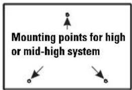
text_image
Mounting points for high or mid-high system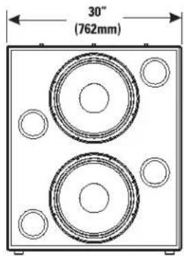
text_image
30" (762mm)
text_image
4" (102mm) 35" (889mm) 18" 457mm) 20" 508mm
TD-000141-00 rev.D
© Copyright 2003, 2004, QSC Audio Products, Inc.
QSC® is a registered trademark of QSC Audio Products, Inc.
"OSC" and the OSC logo are registered with the U.S. Patent and Trademark Office
Connections
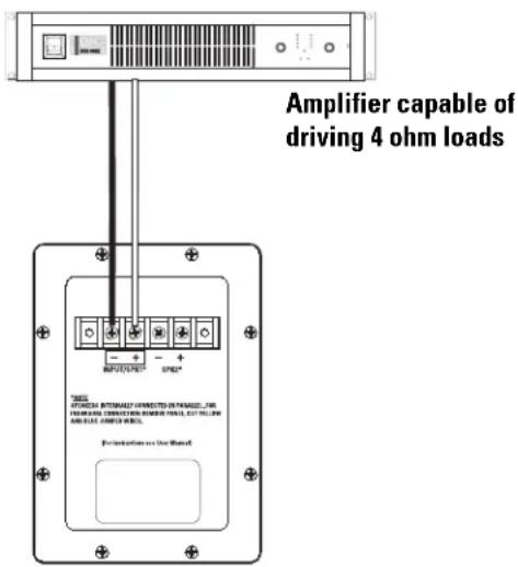
Normal Connection
The LF-4215 has barrier strip screw terminals for connection. The terminals accept up to #10 AWG stranded loudspeaker wiring. Use the largest wire size and shortest wire length possible for a given installation. Observe the polarity markings and keep polarity consistent throughout the system for best performance.
Normal Connection Example:
Parallel Connection of Second SB-5218
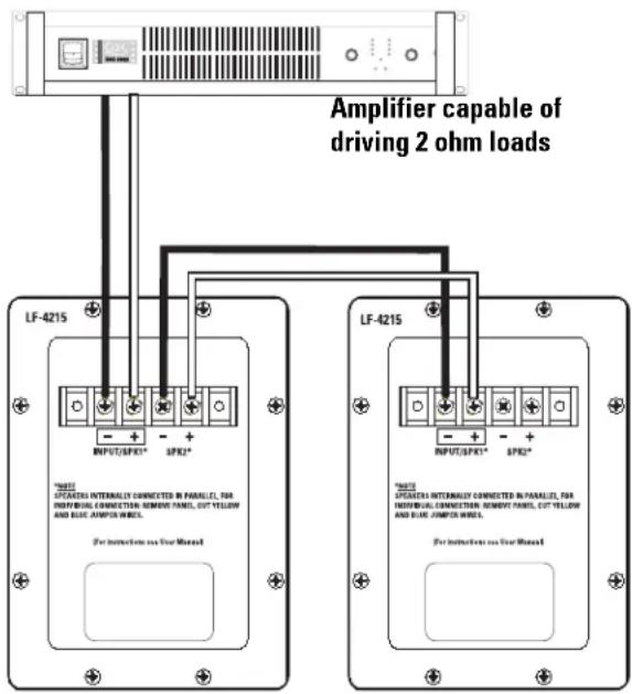
The terminals marker SPK2 may be used to connect another LF-4215 in parallel. Connect the wires as shown in the illustration, at right. Note: If the LF-4215's internal wiring has been modified in any way, this may not function. If this is the case, remove the terminal cup and verify the presence of the factory yellow jumper and blue jumper wires; remedy as required or have the loudspeaker serviced.
Parallel Connection Example:
text_image
Amplifier capable of driving 2 ohm loads LF-4215 * 注释 UPDATES internally connected in parallel, for INDIVIDUAL CONNECTION, REMOVED PANEL, CUT YELLOW AND BLUE AMPOWER WHEEL. For instructions on Your Manual LF-4215 * 注释 UPDATES internally connected in parallel, for INDIVIDUAL CONNECTION, REMOVED PANEL, CUT YELLOW AND BLUE AMPOWER WHEEL. For instructions on Your ManualIndividual Transducer Connection (requires modification)
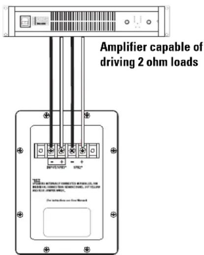
The transducers are wired in parallel inside the enclosure. If individual transducer connection is required, remove the terminal cup and remove the yellow and the blue jumper wires that are connected between the SPK1 and SPK2 terminals. Replace the terminal cup and mark the enclosure with a note of the modification.
Individual Transducer Connection Example:

CAUTION!
Requires removal
of terminal cup
and cutting of both the yellow and the blue jumper wires that connect the SPK1 and SPK2 terminals
text_image
Amplifier capable of driving 2 ohm loads IMPACTED* SPR* FOR INJUNCTION AND CONNECTOR IMPLACEMENT, FOR INJUNCTION, LAYOUT OR RECONNECTOR, FOR YELLOW AND NOT COATED ON/OFF. For INJUNCTION AND CONNECTORLF-4215 Specifications (subject to change without notice)
Frequency Range: 38 - 1300 Hertz (±3 dB)
30 - 1400 Hertz useable range (-10 dB)
Nominal Coverage: 100° horizontal X 55° vertical at 600 Hertz
Maximum Output:
134.5 dB SPL calculated peak, 1 meter, half space, at rated rms power with 6 dB crest factor pink noise input, 25 - 250 Hertz. 128.5 dBA SPL calculated maximum continuous, 1 meter. The dBA scale is typically used to identify sound sources which can cause permanent hearing loss.
Impedance: 4 ohms nominal
3.4 ohms minimum, 150 Hertz
25 ohms maximum, 22 Hertz
Maximum Input Power:
800 watts rms (100 hours of 6 dB crest factor pink noise, 30 - 500 Hertz)
1000 watts rms (2 hours of 6 dB crest factor pink noise, 30 - 500 Hertz, AES method)
recommended amplifier power capability- 1600 watts rms maximum into 4 ohms (per LF-4218)
Sensitivity: 99.5 dB half space, 93.5 dB full space, 35 - 1000 Hertz, 1 watt, 1 meter
Recommended Processing:
Subsonic filter below 30 Hertz, >18 dB per octave, maximum recommended crossover frequency is 1000 Hertz. QSC DSP configurations are available at www.qscaudio.com. Parameters for alternative processing hardware are available upon request.
Connectors:
Barrier strip screw terminals accept up to #10 AWG stranded wire. Four terminals: (two INPUT and two PARALLEL OUT). Drivers are internally wired in parallel. For independent transducer connection, remove blue jumper wire and yellow jumper wire on internal-side of terminal cup and mark enclosure accordingly.
Transducers:
Two 15" (381mm) high efficiency low frequency transducers featuring vented 4" (100mm) copper voice coils on Kapton® formers. High excursion/low distortion design, with extremely high power handling, and low thermal and port compression.
Enclosure:
Quasi B4 alignment, ported enclosure with fully flared ports, low turbulence symmetrical port design, tuned to 36 Hertz, constructed of medium density fibreboard and heavily braced. Features vandal resistant woofer mounting bolts.
Size: 30" wide X 35" high X 20" deep (762 mm X 889 mm X 508 mm)
Weight: 195 lbs. shipping, 172 lbs. net (88/78 kg.)
line
| Frequency (Hertz) | SPL 2pi (dB) | SPL 4pi (dB) | Impedance (ohms) | | ----------------- | ------------ | ------------ | ---------------- | | 10 | 65 | - | - | | 20 | 85 | - | - | | 50 | 100 | 95 | - | | 100 | 100 | 98 | - | | 200 | 100 | 100 | - | | 500 | 100 | 100 | - | | 1K | 105 | 102 | - | | 2K | 90 | 95 | - | | 5K | 70 | 80 | - | | 10K | - | - | 25 |Warranty (USA only; other countries, see your dealer or distributor)
Disclaimer
QSC Audio Products, Inc. is not liable for any damage to amplifiers, or any other equipment that is caused by negligence or improper installation and/or use of this loudspeaker product.
QSC Audio Products 3 Year Limited Warranty
QSC Audio Products, Inc. ("QSC") guarantees its products to be free from defective material and / or workmanship for a period of three (3) years from date of sale, and will replace defective parts and repair malfunctioning products under this warranty when the defect occurs under normal installation and use - provided the unit is returned to our factory or one of our authorized service stations via pre-paid transportation with a copy of proof of purchase (i.e., sales receipt). This warranty provides that the examination of the return product must indicate, in our judgment, a manufacturing defect. This warranty does not extend to any product which has been subjected to misuse, neglect, accident, improper installation, or where the date code has been removed or defaced. QSC shall not be liable for incidental and/or consequential damages. This warranty gives you specific legal rights. This limited warranty is freely transferable during the term of the warranty period.
Customer may have additional rights, which vary from state to state.
In the event that this product was manufactured for export and sale outside of the United States or its territories, then this limited warranty shall not apply. Removal of the serial number on this product, or purchase of this product from an unauthorized dealer, will void this limited warranty. Periodically, this warranty is updated. To obtain the most recent version of QSC's warranty statement, please visit www.qscaudio.com. Contact us at 800-854-4079 or visit our website at www.qscaudio.com.
Contacting QSC Audio Products
Mailing address: QSC Audio Products, Inc.
1675 MacArthur Boulevard
Costa Mesa, CA 92626-1468 USA
Telephone Numbers:
Main Number (714) 754-6175
Sales & Marketing (714) 957-7100 or toll free (USA only) (800) 854-4079
Customer Service(714) 957-7150 or toll free (USA only) (800) 772-2834
Facsimile Numbers:
Sales & Marketing Fax(714) 754-6174
Customer Service Fax(714) 754-6173
World Wide Web:www.qscaudio.com
E-mail:info@qscaudio.com
service@qscaudio.com
natural_image
Technical line drawing of a mechanical assembly with no visible text or symbols
text_image
21" (533mm) 30" (762mm)
text_image
16" (406mm)
text_image
20" (508mm)Conexiones
service@qscaudio.com
natural_image
Technical line drawing of a two-tiered speaker enclosure with circular cutouts and mounting holes (no text or symbols)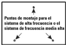
text_image
30" (762mm)
text_image
4" (102mm) 35" (889mm) 18" 457mm) 20" 508mmConexiones
Conexión normal
service@qscaudio.com
natural_image
Technical line drawing of a mechanical assembly with a pulley and housing (no text or symbols)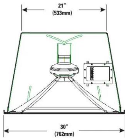
text_image
21" (533mm) 30" (762mm)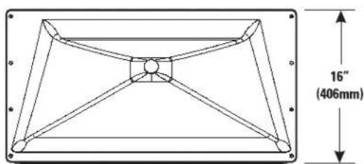
text_image
16" (406mm)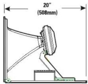
text_image
20" (508mm)Branchements
Adresse postale : QSC Audio Products, Inc.
1675 MacArthur Boulevard
service@qscaudio.com
natural_image
Line drawing of a two-tiered speaker chamber with circular cutouts and mounting holes (no text or symbols)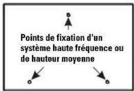
text_image
30" (762mm)
text_image
4" (102mm) 35" (889mm) 18" 457mm) 20" 508mmBranchements
Branchement normal
text_image
Amplificateur capable de piloter des charges de 2 ohms LF-4215 *NOTE APPLICERS INTERNALLY CONNECTED IN PARALLEL, FOR INDIVIDUAL CONNECTION, REMOVE PANEL, CUT YELLOW AND BLUE AMPTOR WHEEL. For instructions as Your Manual LF-4215 *NOTE APPLICERS INTERNALLY CONNECTED IN PARALLEL, FOR INDIVIDUAL CONNECTION, REMOVE PANEL, CUT YELLOW AND BLUE AMPTOR WHEEL. For instructions as Your ManualAdresse postale : QSC Audio Products, Inc.
1675 MacArthur Boulevard
service@qscaudio.com
natural_image
Technical line drawing of a mechanical assembly with a pulley and housing (no text or symbols)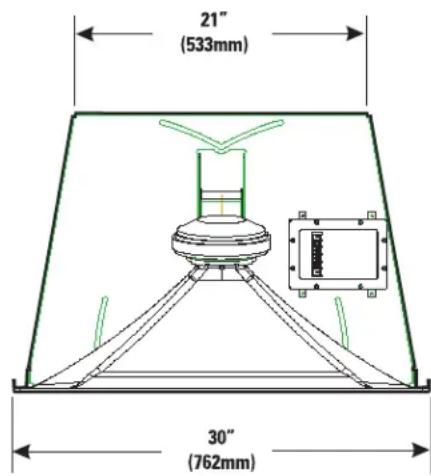
text_image
21" (533mm) 30" (762mm)
text_image
16" (406mm)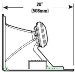
text_image
20" (508mm)Verbindungen
service@qscaudio.com
natural_image
Technical line drawing of a two-tiered speaker enclosure with circular cutouts and mounting holes (no text or symbols)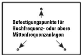
text_image
30" (762mm)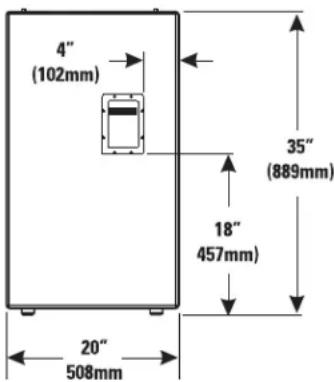
text_image
4" (102mm) 35" (889mm) 18" 457mm) 20" 508mmVerbindungen
Normaler Anschluss
service@qscaudio.com
影院扬声器系统用户手册
HF-75 高频组件
简介
natural_image
Technical line drawing of a mechanical assembly with no visible text or symbols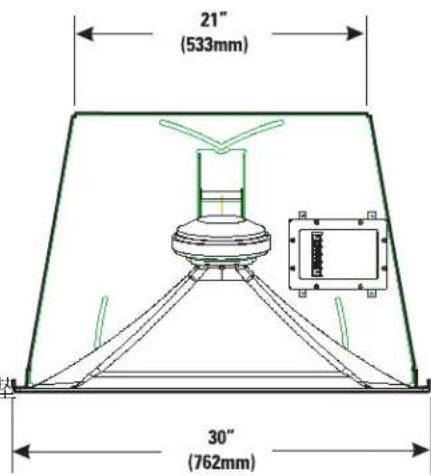
text_image
21" (533mm) 30" (762mm)
text_image
16" (406mm)
text_image
20" (508mm)连接
service@qscaudio.com
影院扬声器系统用户手册
LF-4215 低频扬声器
简介
natural_image
Line drawing of a two-tiered speaker enclosure with circular cutouts and mounting holes (no text or symbols)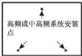
text_image
4" (102mm) 35" (889mm) 18" 457mm) 20" 508mm连接
正常连接
service@qscaudio.com