
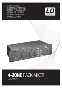
Zone 622 - Mixer LD Systems - Free user manual and instructions
Find the device manual for free Zone 622 LD Systems in PDF.
| Product Type | Zone Mixer |
| Model Reference | LDZONE622 |
| Total Number of Input Channels | 8 (2 x Mic, 2 x Mic/Line, 3 x Line, 1 x FOH) |
| Microphone Inputs | 2 on balanced 6.35 mm jack, with 12 V phantom power |
| Line Inputs | 3 stereo on RCA, 2 line/micro inputs, 1 FOH input on balanced 6.35 mm jack |
| Line Outputs | Stereo Master (6.35 mm jack, RCA, Euroblock), Mono Zone (6.35 mm jack, Euroblock), Stereo Rec (RCA) |
| Headphone Output | 1 on stereo 6.35 mm jack, with volume control |
| Equalizers | Master EQ Hi/Low, Zone EQ Hi/Low, Micro EQ Hi/Low (all with center detent) |
| Special Functions | Talkover, Cue, Emergency input, Remote muting control |
| USB Port | 16-bit audio interface, compatible USB 1.1/2.0 (recording and playback) |
| Power Supply Voltage | 220-250 V AC, 50 Hz |
| Power Consumption | 18 W max |
| Fuse | T 500 mAL / 250 V |
| Dimensions (W x H x D) | 485 x 44 x 179 mm |
| Weight | 2,44 kg |
| Included Accessories | Power cord, Euroblock connectors, user manual |
| Manufacturer Warranty | Limited, 2 to 5 years depending on product |
| Maintenance | Clean with a dry cloth. Do not open the device. |
| Safety | Follow instructions: avoid humidity, do not block vents, use a grounded outlet. |
| Environment | Do not dispose of with household waste. Recycle according to local regulations. |
Frequently Asked Questions - Zone 622 LD Systems
User questions about Zone 622 LD Systems
0 question about this device. Answer the ones you know or ask your own.
Ask a new question about this device
Download the instructions for your Mixer in PDF format for free! Find your manual Zone 622 - LD Systems and take your electronic device back in hand. On this page are published all the documents necessary for the use of your device. Zone 622 by LD Systems.
USER MANUAL Zone 622 LD Systems
You've made the right choice!
We have designed this product to operate reliably over many years. LD Systems stands for this with its name and many years of experience as a manufacturer of high-quality audio products.
Please read this User's Manual carefully, so that you can begin making optimum use of your LD Systems product quickly.
You can find more information about LD SYSTEMS at our Internet site WWW.LD-SYSTEMS.COM
Introduction
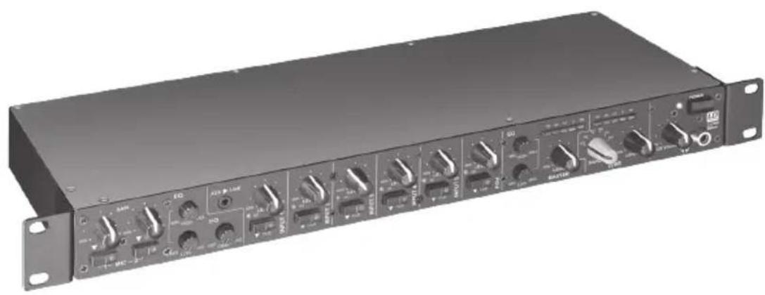
The ZONE 622 is a particularly compact 1U zone mixer with 6 line and 2 microphone channels, that can be assigned to a stereo or a mono master output. The device has all the main features, an input for an external emergency announcement system with its own volume control and a connection to the remote mute. The ZONE 622 is suitable as a sound system for separate areas in restaurants, clubs, hotels, fitness centres, and for presentations.
2-ZONE RACK MIXER
LDZONE622
PREVeNTIVE MEASURES:
- Please read these instructions carefully.
- Keep all information and instructions in a safe place.
- Follow the instructions.
- Observe all safety warnings. Never remove safety warnings or other information from the equipment.
- Use the equipment only in the intended manner and for the intended purpose.
- Use only sufficiently stable and compatible stands and/or mounts (for fixed installations). Make certain that wall mounts are properly installed and secured. Make certain that the equipment is installed securely and cannot fall down.
- During installation, observe the applicable safety regulations for your country.
- Never install and operate the equipment near radiators, heat registers, ovens or other sources of heat. Make certain that the equipment is always installed so that is cooled sufficiently and cannot overheat.
- Never place sources of ignition, e.g., burning candles, on the equipment.
- Ventilation slits must not be blocked.
- Do not use this equipment in the immediate vicinity of water (does not apply to special outdoor equipment - in this case, observe the special instructions noted below. Do not expose this equipment to flammable materials, fluids or gases.
- Make certain that dripping or splashed water cannot enter the equipment. Do not place containers filled with liquids, such as vases or drinking vessels, on the equipment.
- Make certain that objects cannot fall into the device.
- Use this equipment only with the accessories recommended and intended by the manufacturer.
- Do not open or modify this equipment.
- After connecting the equipment, check all cables in order to prevent damage or accidents, e.g., due to tripping hazards.
- During transport, make certain that the equipment cannot fall down and possibly cause property damage and personal injuries.
- If your equipment is no longer functioning properly, if fluids or objects have gotten inside the equipment or if it has been damaged in anot her way, switch it off immediately and unplug it from the mains outlet (if it is a powered device). This equipment may only be repaired by authorized, qualified personnel.
- Clean the equipment using a dry cloth.
- Comply with all applicable disposal laws in your country. During disposal of packaging, please separate plastic and paper/cardboard.
- Plastic bags must be kept out of reach of children.
FOR EQUIPMENT That Connects to THE POWER maINS:
- CAUTION: If the power cord of the device is equipped with an earthing contact, then it must be connected to an outlet with a protective ground. Never deactivate the protective ground of a power cord.
- If the equipment has been exposed to strong fluctuations in temperature (for example, after transport), do not switch it on immediately. Moisture and condensation could damage the equipment. Do not switch on the equipment until it has reached room temperature.
- Before connecting the equipment to the power outlet, first verify that the mains voltage and frequency match the values specified on the equipment. If the equipment has a voltage selection switch, connect the equipment to the power outlet only if the equipment values and the mains power values match. If the included power cord or power adapter does not fit in your wall outlet, contact your electrician.
- Do not step on the power cord. Make certain that the power cable does not become kinked, especially at the mains outlet and/or power adapter and the equipment connector.
- When connecting the equipment, make certain that the power cord or power adapter is always freely accessible. Always disconnect the equipment from the power supply if the equipment is not in use or if you want
SAFeTY:
to clean the equipment. Always unplug the power cord and power adapter from the power outlet at the plug or adapter and not by pulling on the cord. Never touch the power cord and power adapter with wet hands.
- Whenever possible, avoid switching the equipment on and off in quick succession because otherwise this can shorten the useful life of the equipment.
- IMPORTANT INFORMATION: Replace fuses only with fuses of the same type and rating. If a fuse blows repeatedly, please contact an authorised service centre.
- To disconnect the equipment from the power mains completely, unplug the power cord or power adapter from the power outlet.
- If your device is equipped with a Volex power connector, the mating Volex equipment connector must be unlocked before it can be removed. However, this also means that the equipment can slide and fall down if the power cable is pulled, which can lead to personal injuries and/or other damage. For this reason, always be careful when laying cables.
- Unplug the power cord and power adapter from the power outlet if there is a risk of a lightning strike or before extended periods of disuse.
CAUTION:
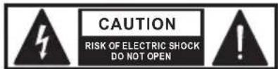
Never remove the cover, because otherwise there may be a risk of electric shock. There are no user serviceable parts inside. Have repairs carried out only by qualified service personnel.
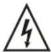
The lightning flash with arrowhead symbol within an equilateral triangle is intended to alert the user to the presence of uninsulated "dangerous voltage" within the product's enclosure that may be of sufficient magnitude to constitute a risk of electrical shock.

The exclamation mark within an equilateral triangle is intended to alert the user to the presence of important operating and maintenance instructions.
CAUTION - HIGH VOLUME LeVeLS WITH AUDIO PRODUCTS!
This equipment is intended for professional use. Therefore, commercial use of this equipment is subject to the respectively applicable national accident prevention rules and regulations. As a manufacturer, Adam Hall is obligated to notify you formally about the existence of potential health risks.
Hearing damage due to high volume and prolonged exposure: When in use, this product is capable of producing high sound-pressure levels (SPL) that can lead to irreversible hearing damage in performers, employees, and audience members. For this reason, avoid prolonged exposure to volumes in excess of 90 dB.
NOTE: For rack installation please ensure adequate ventilation above and below the unit!
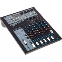
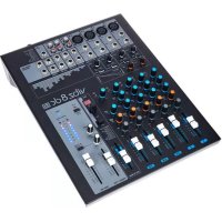
CONNECTIONS, CONTROLS, AND INDICATORS:
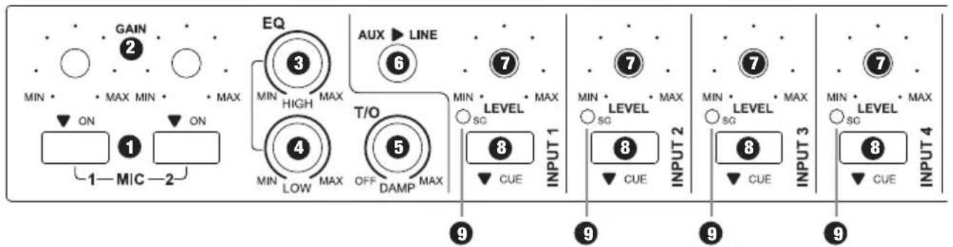
MIC1/2ON
On/Off switch for the microphone channels 1 and 2 with built-in red LED. When button is pressed, the microphone channel is switched on and the LED light turns on.
GAIN MIC 1/2
Volume control for the microphone inputs 1 and 2.
eQ HIGH MIC 1 / 2
Equalizer high band for the microphone channels 1 and 2. When turned to the left, levels are lowered, when turned to the right, they are raised. In the centre position (resting point), the equalizer is inactive.
eQ LOW MIC 1/2
Equalizer low band for microphone channels 1 and 2. When turned to the left, levels are lowered, when turned to the right, they are raised. In the centre position (resting point), the equalizer is inactive.
5 T/O DAMP
Talkover feature for microphone channels 1 and 2. If the DAMP knob is turned fully to the left, the Talkover feature is disabled. The further the DAMP knob is turned to the right, the stronger the signals at the INPUT 1 - 5 will be suppressed by the incoming microphone signal. The threshold value is determined using the T/O LEVEL control on the rear panel (sensitivity with which the Talkover feature reacts to the incoming microphone signal). The Talkover feature is not available for the ZONE output
when a signal source from INPUT 1 - 5 is selected using the SOURCE switch.
AUX / LINE
Stereo line input with 3.5mm jack and switching function. If a 3.5mm jack is inserted in this sokket, the RCA connectors of the INPUT 1 channel on the rear panel of the device are turned off.
7 LeVeL INPUT 1 - 5 & FOH
Volume control for the channels INPUT 1 - 5 and FOH.
CUE INPUT 1-5 & FOH
Cue switch with built-in red LED for INPUT channels 1 - 5. If the switch is pressed (LED is on), the input signal is routed to the headphone output on the front panel of the device. The signal is sourced before the volume control (LEVEL INPUT 1 - 5 and FOH) of each channel, therefore it is independent of the setting of the volume control.
SG LeD INPUT 1-5 & FOH
The signal LED lights up green when an audio signal is present at the input of the respective channel.
10 MASTeR eQ HIGH
Equalizer high band for the MASTER output. When turned to the left, levels are lowered, when turned to the right, they are raised. In the centre position (resting point), the equalizer is inactive.
CONNECTIONS, CONTROLS, AND INDICATORS:
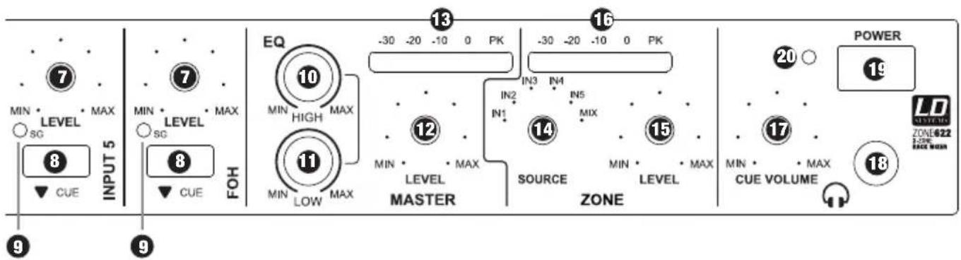
MASTeR eQ LOW
Equalizer low band for the MASTER output. When turned to the left, levels are lowered, when turned to the right, they are raised. In the centre position (resting point), the equalizer is inactive.
MASTeR LeVeL
Volume control for the MASTER output on the rear panel of the unit.
13 MASTeR AUDIO LeVel MeTeR
Level meter display with 5 LED segments. Once the peak LED (PK) lights up, the device is operating at the distortion limit. It is not critical if the LED lights briefly at peak levels for the incoming signal, however continuous illumination should be avoided by reducing the volume.
1ZONE SOURCE
Selection of the signal source to be connected to the zone output. Alternatively, one of the 5 input channels (IN 1 - 5), or a mix (MIX) from all input channels (MIC 1 and 2, INPUT 1 - 5, FOH) can be selected.
15 ZONE LeVeL
Volume control for the zone output (ZONE) on the back of the unit.
ZONE AUDIO LeVeL MeTeR
Level meter display with 5 LED segments. Once the peak LED (PK) lights up, the device is operating at the distortion limit. It is not critical if the LED lights briefly at peak levels for the incoming signal, however continuous illumination should be avoided by reducing the volume.
CUe VOLUME
Headphone volume control Channels, for which the CUE button is pressed (INPUT 1 - 5 & FOH) can be listened to on the headphones output regardless of their volume control setting.
HeADPHONE OUTPUT
Headphone output with 6.3 mm stereo jack.
10POWeR
On/Off switch for the device.
20POWeR LeD
Lights up once the system is properly connected to the power mains and switched on.
CONNECTIONS, CONTROLS, AND INDICATORS:
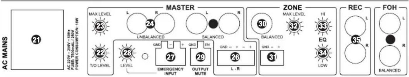
leCPOWeR SOCKETWITHINTeGRATeD FUSE HOLDeR
IMPORTANT INFORMATION: BEFORE using this equipment, make certain that the mains voltage of your energy utility and the operating voltage of the device match! Always replace the fuse only with a fuse of the same type with the same rating (printed on the rear panel)! If the fuse blows repeatedly, please contact an authorised service centre.
2 T/O LeVeL
The threshold value of the Talkover is determined using the T/O LEVEL control (sensitivity with which the Talkover feature reacts to the incoming microphone signal). The Talkover feature is available for the MASTER and ZONE line outputs (SOURCE switch set to MIX).
MASTeR MAX LeVeL
Adjust the maximum volume of the MASTER output with a suitable screwdriver.
MASTeR OUTPUT L/R UNBALANCeD
Unbalanced stereo output with RCA jacks (left / right). The signal of the MASTER output consists of the sum of the signals of the MIC 1 and 2, INPUT 1 to 5 and FOH channels.
MASTeR OUTPUT L/R BALANCED
Balanced stereo output with 6.3mm jacks (left / right). The signal of the MASTER output consists of the sum of the signals of the MIC 1 and 2, INPUT 1 to 5 and FOH channels.
26 MASTeR OUTPUT L/R BALANCED
Balanced stereo output (left / right) with terminal block connector (terminal block included). The signal of the MASTER output consists of the sum of the signals of the MIC 1 and 2, INPUT 1 to 5 and FOH channels.
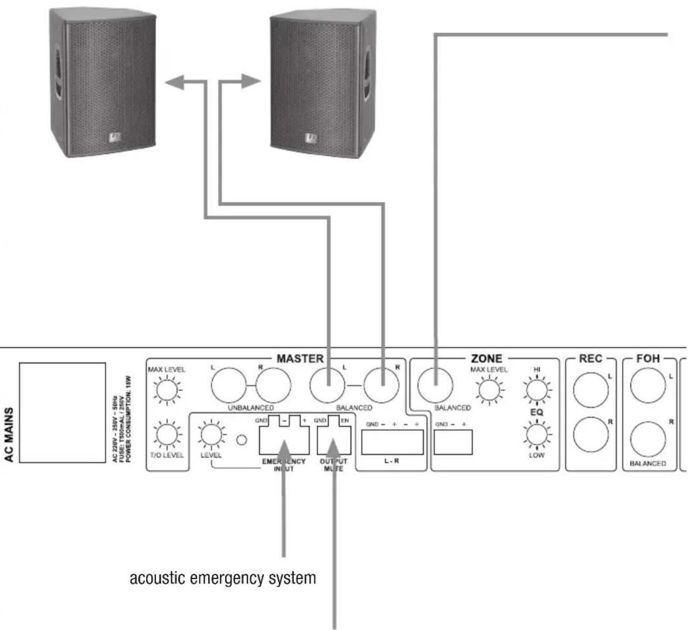
eMeRGeNcy INPUT
Symmetrical terminal block connector for an acoustic emergency response system (terminal block included). As soon as an audio signal with line-level is detected, all microphone and line inputs are muted, and the emergency signal is directly connected to the MASTER and ZONE line outputs. The volume controls on the MASTER and ZONE channels are then inactive.
eMeRGeNCY INPUT LeVeL
Adjust the volume of the emergency signal with a suitable screwdriver.
29 OUTPUT MUTE
Terminal block connector for connecting a potential free contact or a mute switch (terminal block included). When the contact is closed, all input channels are muted except for the EMERGENCY INPUT.
CONNECTIONS, CONTROLS, AND INDICATORS:
30 ZONE OUTPUT BALANCED
Balanced mono output with 6.3mm jack. The signal from the ZONE output may be the sum of the signals of the MIC 1-2 inputs and INPUT 1-5 and FOH (ZONE SOURCE switch 14 on the front of the unit set on MIX), or the signal of one of the INPUTS 1-5 (ZONE SOURCE switch 14 on the front of the device set to one of the INPUTS 1-5).
ZONE OUTPUT BALANCED
Balanced mono output with terminal block connection (terminal block included). The signal from the ZONE output may be the sum of the signals of the MIC 1 - 2 inputs and INPUT 1-5 and FOH (ZONE SOURCE switch 14 on the front of the unit set on MIX), or the signal of one of the INPUTS 1 - 5 (ZONE SOURCE switch 14 on the front of the device set to one of the INPUTS 1 - 5).
ZONE MAX LeVeL
Adjust the maximum volume of the ZONE output with a suitable screwdriver.
ZONE eQ HIGH
Equalizer high band for the ZONE output. When turned to the left, levels are lowered, when turned to the right, they are raised. In the centre position (resting point), the equalizer is inactive.
ZONE eQ LOW
Equalizer low band for the ZONE output. When turned to the left, levels are lowered, when turned to the right, they are raised. In the centre position (resting point), the equalizer is inactive.
ReC OUTPUT L/R
Unbalanced stereo line output on RCA connectors (left / right). The signal from the REC output consists of the sum of the signals of the inputs MIC 1 and 2 and INPUT 1 - 5 and FOH. The output level is independent of the setting of the volume control of the MASTER output. The signal is sourced before the EQ, therefore, it remains unprocessed.
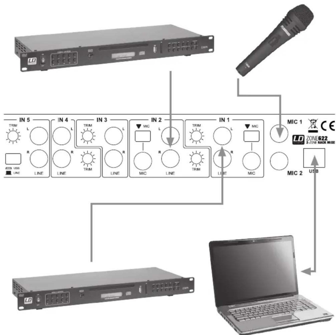
FOH INPUT L/R
Balanced stereo line input with 6.3mm jacks (left / right). Connection option for a playback device (e.g. mixer).
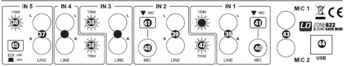
LINEIN3-5
Unbalanced stereo line inputs 3 to 5 with RCA jacks (left/right).
TRIM3-5
To harmonise playback devices (CD player, MP3 player etc.) with different output levels, adjust the input gain of the channels 3 - 5 with a suitable screwdriver.
This also applies to the playback signal from the USB-interface in channel 5.
39 LINE INPUT 1-2
Unbalanced stereo line inputs 1 to 2 with RCA jacks (left/right).
CONNECTIONS, CONTROLS, AND INDICATORS:
MIC INPUT 1 - 2
Balanced microphone inputs INPUT 1 and 2 with a 6.3mm jack. There is no phantom power on these microphone inputs.
MIC SWITCH INPUT 1-2
In pressed position, the microphone input of the respective channel is active and the line input is muted.
TRIM INPUT 1-2
Switch 41 in the released position: To harmonise playback devices (CD player, MP3 player etc.) with different output levels, adjust the input gain of the channels 3 - 5 with a suitable screwdriver.
Switch 41 in the pressed position: Pre-amplification for the microphone input. Use a suitable screwdriver to adjust.
43 MIC1-2
Balanced microphone inputs 1 and 2 with a 6.3 mm jack. Both microphone inputs are equipped with a 12V phantom power.
44 USB
The USB-interface (USB 1.1) allows for the mixer to be used as an audio interface. In other words, audio recording and playback can be done through a connected computer with Windows Operating System (Windows XP, Vista, 7, 8) and Apple Macintosh OS 10.5 or higher. Separate drivers are not necessary for the installation. Once connected to a suitable USB port on your computer (USB 1.1, USB 2.0), the drivers are automatically installed. The audio interface is detected as "USB Audio CODEC" interface on both Windows and Apple Macintosh computers.
The recording signal consists of the sum signal which is sourced after the master level control and the max level control, and is therefore dependent on it. Audio playback is via the line channel INPUT 5. This requires the switch 45 on the back panel to be pressed (USB).
USB / LINE
Switch for selecting the signal source for the line channel INPUT 5. In pressed position, the USB-interface (44) is selected, if not pressed, the line input (37) is selected as the signal source.
potential free contact / mute switch
WIRING EXAMPLE:
SPECIFICATIONS:
| Model Name: LDZONE622 | |
| Product Type: zone mixer | |
| Type: stereo | |
| Total Input Channels: 8 (2x Mic, 2x Mic/Line, 3x Line. | 1x FOH) |
| Frequency Response: 20 - 40000 Hz | |
| Microphone Channels: 2 (with phantom power 12 V) | |
| Microphone Channels Connections: 6.3 mm jack (balanced) | |
| Microphone Channel Controls: Gain, On/Off, 1 x EQ H | 1 x EQ Low, 1 x Talk Over Damp, 1 x Talk Over Level |
| Microphone Channels Display Elements: On-LED | |
| Microphone Channels Input Impedance: 4 kOhm | |
| Microphone Channels Input Sensitivity: 6.1 mV | |
| Microphone Channels THD: 0.08 % | |
| Line / Microphone Channels: 2 | |
| Line / Microphone Input Connectors: | 2x RCA, 6.3 mm jack (unbalanced), 3.5 mm stereo jack (input 1) |
| Line / Microphone Channel Controls: | Level, Cue, Mic/Line, Trim |
| LINE/MIC Channels Display Elements: | Signal-LED, Cue-LED |
| Line Channels: | 3 |
| Line Input Connectors: | 2x RCA |
| Line Channel Controls: | Level, Cue, Trim |
| Line Channels Display Elements: | Signal-LED, Cue-LED |
| Line Channel Input Impedance: | 4 kOhm |
| Line Channels Input Sensitivity: | 1.5 V |
| Line Channels THD: | 0.03 % |
| Input Sensitivity AUX/Line (3.5 mm stereo jack): | 3 V |
| FOH Channels: | 1 |
| FOH Input Connections: | 2 x 6.3 mm jack balanced |
| FOH Input Controls: | Level, Cue |
| FOH Input Display Elements: | Signal-LED, Cue-LED |
| Line Outputs: 3 (Master - Stereo, Zone - Mono, Rec - Stereo) | |
| Master Output Connectors: | 2 x 6.3 mm jack balanced, 2 x RCA, terminal block |
SPECIFICATIONS:
| Master Controls: Level, EQ Hi, EQ Low, Max. Level | |
| Master Display Elements: 5-segment level meter | |
| Master Output Levels: 24 dBu (balanced), 18 dBu (unbalanced) | |
| Zone Output Connections: 6.3 mm jack (balanced), terminal block | |
| Zone Controls: Level, EQ Hi, EQ Low, Max. Level, Source Input 1-5/Mix | |
| Zone Display Elements: 5-segment level meter | |
| Zone Output Levels: 24 dBu (balanced/ unbalanced) | |
| Output Connections Rec: 2x RCA | |
| Headphone Output: 1 | |
| Headphone Out Port: 6.3 mm jack stereo | |
| Headphone Output Controls: Cue Volume | |
| Headphone Output Voltage: 1.25 V @ 32 Ohm | |
| Additional Inputs: 2 (Emergency Input, Output Mute) | |
| Additional Input Connections: | terminal block |
| Additional Input Controls: | level emergency input |
| Additional Controls: | power switch |
| Additional Display Elements: | Power-LED |
| Operating Voltage: | 220 - 250 V AC, 50 Hz |
| Power Socket: IEC power socket | |
| Power Consumption (max.): | 18 W |
| Fuse: | T 500 mAL / 250 V |
| Dimensions (W x H x D): | 485 x 44 x 179 mm |
| Weight: | 2.44 kg |
| Accessories Included: | terminal blocks, power cable, operating instructions |
| Other Features: | USB 1.1 interface (compatible with USB 2.0) for use as an audio interface (16 Bit, recording and playback). Supported Operating Systems: Windows XP, Vista, 7, 8, and Apple Macintosh 10.5 or higher |
MANUFACTURER'S DECLARATIONS:
MANUFACTURE'S WARRANTY
This warranty covers the Adam Hall, LD Systems, Defender, Palmer, and Cameo brands.
It applies to all products distributed by Adam Hall.
This warranty declaration does not affect the statutory warranty claims against the manufacturer, but expands them with additional warranty claims vis-a-vis Adam Hall.
Adam Hall warrants that the Adam Hall product that you have purchased from Adam Hall or from an Adam Hall authorized reseller is free from defects in materials or workmanship under normal use for a period of 2 or 5 years (please inquire on a product-by-product basis) from the date of purchase.
The warranty period begins on the date on which the product was purchased, proof of which must be produced (through presentation of the invoice or the delivery note with the date of purchase) in the event of a warranty claim. Should products of the brands named above be in need of repair within the limited warranty period, you are entitled to warranty service according to the terms and conditions stated here.
During the Limited Warranty Period, Adam Hall will repair or replace the defective component parts or the product. In the event of repair or replacement during the Limited Warranty Period, the replaced original parts and/or products become property of Adam Hall.
In the unlikely event that the product which you purchased has a recurring failure, Adam Hall has the right, at its discretion, to replace the defective product with another product, provided that the new product is at least equivalent to the product being replaced with regard to the technical specifications.
Adam Hall does not warrant that the operation of this product will be uninterrupted or error-free. Adam Hall is not responsible for damage that occurs as a result of your failure to follow the instructions included with the Adam Hall branded product. The manufacturer's warranty does not cover - expendable parts (e.g., rechargeable batteries) - products from which the serial number has been removed or with a serial number that has been damaged as a result of an accident - damage due to improper use, user error or other external reasons
- damage to devices operated outside the usage parameters stated in the documentation included with the product
- damage due to the use of replacement parts not manufactured, sold or recommended by Adam Hall,
- damage due to modification or servicing by anyone other than Adam Hall.
These terms and conditions constitute the complete and exclusive warranty agreement between you and Adam Hall regarding the Adam Hall branded product you have purchased.
MANUFACTURER'S DECLARATIONS:
LIMITATION OF LIABILITY
If your Adam Hall branded hardware product fails to work as warranted above, your sole and exclusive remedy shall be repair or replacement. Adam Halls' maximum liability under this limited warranty is expressly limited to the lesser of the price you have paid for the product or the cost of repair or replacement of any components that malfunction under conditions of normal use.
Adam Hall is not liable for any damages caused by the product or the failure of the product, including any lost profits or savings or special, incidental, or consequential damages. Adam Hall is not liable for any claim made by a third party or made by you for a third party.
This limitation of liability applies whether damages are sought, or claims are made, under this Limited Warranty or as a tort claim (including negligence and strict product liability), a contract claim, or any other claim, and cannot be rescinded or changed by anyone. This limitation of liability will be effective even if you have advised Adam Hall or an authorized representative of Adam Hall of the possibility of any such damages, but not, however, in the event of claims for damages in connection with personal injuries.
This manufacturer's warranty grants you specific rights; depending on jurisdiction (nation or state), you may be entitled to additional claims. You are advised to consult applicable state or national laws for a full determination of your rights.
REQUESTING WARRANTY SeRvIce
To request warranty service for the product, contact Adam Hall or the Adam Hall authorized reseller from which you purchased the product.
eC DeCLARATION OF CONFORMITY
The equipment marketed by Adam Hall complies (where applicable) with the essential requirements and other relevant specifications of Directives 1999/5/EC (R&TTE), 2004/108/EC (EMC) und 2006/95/EC (LVD). Additional information can be found at www.adamhall.com.
MANUFACTURER'S DECLARATIONS:
PROPeR DISPOSAL OF THIS PRODUCT

(Valid in the European Union and other European countries with waste separation)
This symbol on the product, or the documents accompanying the product, indicates that this appliance may not be treated as household waste. This is to avoid environmental damage or personal injury due to uncontrolled waste disposal. Please dispose of this product separately from other waste and have it recycled to promote sustainable economic activity.
Household users should contact either the retailer where they purchased this product, or their local government office, for details on where and how they can recycle this item in an environmentally friendly manner. Business users should contact their supplier and check the terms and conditions of the purchase contract. This product should not be mixed with other commercial wastes for disposal.
eNvironMeNTAL PROTeCt iON AND eNeRGY CONSERVATION
Energy conservation is an active contribution to environmental protection. Please turn off all unneeded electrical devices. To prevent unneeded devices from consuming power in standby mode, disconnect the mains plug.
Adam Hall GmbH, all rights reserved. The technical data and the functional product characteristics can be subject to modifications. The photocopying, the translation, and all other forms of copying of fragments or of the integrity of this user's manual is prohibited.
Declarations DECLARATIONS:
ReSPONSABILITE LIMITEE
MISEAU REBUT DE CE PRODUIT
39 LINE (INPUT 1 / 2)
SG LeD INPUT 1-5 I FOH
GWARANCJA PRODUCENTA
DEKLARACJA ZGODNOSCI We

- You've made the right choice!
- Introduction
- 2-ZONE RACK MIXER
- PREVeNTIVE MEASURES:
- FOR EQUIPMENT That Connects to THE POWER maINS:
- SAFeTY:
- CAUTION:
- CAUTION - HIGH VOLUME LeVeLS WITH AUDIO PRODUCTS!
- CONNECTIONS, CONTROLS, AND INDICATORS:
- MASTeR eQ LOW
- MASTeR LeVeL
- MASTeR AUDIO LeVel MeTeR
- 1ZONE SOURCE
- ZONE LeVeL
- ZONE AUDIO LeVeL MeTeR
- CUe VOLUME
- HeADPHONE OUTPUT
- 10POWeR
- 20POWeR LeD
- leCPOWeR SOCKETWITHINTeGRATeD FUSE HOLDeR
- T/O LeVeL
- MASTeR MAX LeVeL
- MASTeR OUTPUT L/R UNBALANCeD
- MASTeR OUTPUT L/R BALANCED
- MASTeR OUTPUT L/R BALANCED
- eMeRGeNcy INPUT
- eMeRGeNCY INPUT LeVeL
- OUTPUT MUTE
- ZONE OUTPUT BALANCED
- ZONE OUTPUT BALANCED
- ZONE MAX LeVeL
- ZONE eQ HIGH
- ZONE eQ LOW
- ReC OUTPUT L/R
- FOH INPUT L/R
- LINEIN3-5
- TRIM3-5
- LINE INPUT 1-2
- MIC INPUT 1 - 2
- MIC SWITCH INPUT 1-2
- TRIM INPUT 1-2
- MIC1-2
- USB
- USB / LINE
- SPECIFICATIONS:
- MANUFACTURER'S DECLARATIONS:
- MANUFACTURE'S WARRANTY
- LIMITATION OF LIABILITY
- REQUESTING WARRANTY SeRvIce
- eC DeCLARATION OF CONFORMITY
- PROPeR DISPOSAL OF THIS PRODUCT
- eNvironMeNTAL PROTeCt iON AND eNeRGY CONSERVATION
- Declarations DECLARATIONS:
- ReSPONSABILITE LIMITEE
- MISEAU REBUT DE CE PRODUIT
- LINE (INPUT 1 / 2)
- SG LeD INPUT 1-5 I FOH
- GWARANCJA PRODUCENTA
- DEKLARACJA ZGODNOSCI We
Brand : LD Systems
Model : Zone 622
Category : Mixer